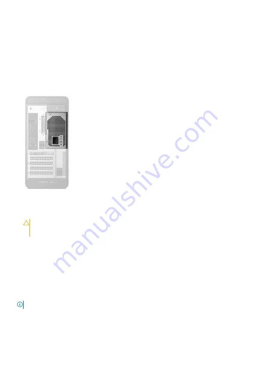
Power-supply unit Built-in Self Test (BIST)
XPS 8930 supports a new power-supply unit Built-in Self Test (BIST). BIST can now be performed by connecting the power cord to the
power-supply unit.
1. Turn off your computer.
2. Disconnect the power cord from the power-supply unit, and wait for 15 seconds.
3. After 15 seconds, connect the power cord to the power-supply unit.
•
If the LED is on for 3 seconds and turns off, it indicates that the power-supply unit is functional. Continue with troubleshooting
steps for other devices.
•
If the LED does not turn on, it indicates a hardware failure.
Steps to confirm that power-supply unit is defective
1. Disconnect the power cord from the power-supply unit.
CAUTION:
Ensure that you take adequate safety precautions before accessing the components on your computer.
See the removing and replacing instructions in the service manual for procedure to access the power-supply unit and
its cables.
2. Disconnect the power-supply unit cables from the system board.
3. Connect the power cord to the power-supply unit.
•
If the LED is on for 3 seconds and turns off, it indicates that the power-supply unit is functional. Continue with troubleshooting
steps for other devices.
•
If the LED does not turn on, it indicates a power-supply unit failure. Replace the power-supply unit only.
Wi-Fi power cycle
If your computer is unable to access the Internet due to Wi-Fi connectivity issues a Wi-Fi power cycle procedure may be performed. The
following procedure provides the instructions on how to conduct a Wi-Fi power cycle:
NOTE:
Some ISPs (Internet Service Providers) provide a modem/router combo device.
1. Turn off your computer.
2. Turn off the modem.
3. Turn off the wireless router.
4. Wait for 30 seconds.
5. Turn on the wireless router.
6. Turn on the modem.
100
Troubleshooting
Содержание XPS 8920
Страница 1: ...XPS 8920 Service Manual Regulatory Model D24M Regulatory Type D24M001 June 2020 Rev A04 ...
Страница 8: ...Chapter 55 Getting help and contacting Dell 102 8 Contents ...
Страница 17: ...Figure 4 Removing the front bezel a front bezel tabs b front bezel c front chassis Removing the front bezel 17 ...
Страница 38: ...3 system board 4 M2x2 5 screw 38 Removing the solid state drive ...
Страница 86: ...Figure 44 Removing the system board a system board b 6 32x1 4 screws 8 c chassis 86 Removing the system board ...
Страница 101: ...7 Turn on your computer Troubleshooting 101 ...


