background image

Replacing Memory Module(s): Dell XPS 430 Service Manual

memory.htm[4/15/2014 11:28:28 AM]

Back to Contents Page

 Replacing Memory Module(s)

Dell™ XPS™ 430 Service Manual

 CAUTION: 

Before working inside your computer, read the safety information that shipped with your

 computer. For additional safety best practices information, see the Regulatory Compliance Homepage at

 www.dell.com/regulatory_compliance.

1.  Follow the procedures in 

Before You Begin

2.  Remove the computer cover (see 

Removing the Computer Cover

). 

3.  Locate the memory modules on the system board (see 

System Board Components

). 

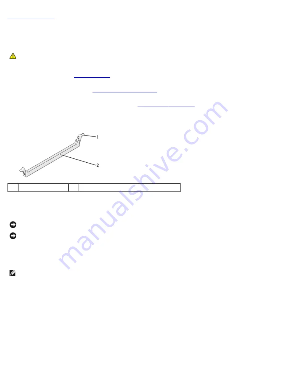
4.  Press out the securing clip at each end of the memory module connector. 

1

securing clip

2

memory module connector

5.  Grasp the module and pull it upwards. 

If the module is difficult to remove, gently ease the module back and forth to remove it from the connector.

NOTICE: 

Do not install ECC memory modules.

NOTICE: 

If you remove your original memory modules from the computer during a memory upgrade, keep them

 separate from any new modules that you may have, even if you purchased the new modules from Dell™. If possible,

 do not pair an original memory module with a new memory module. Otherwise, your computer may not start properly.

 The recommended memory configurations are: 

A pair of matched memory modules installed in DIMM connectors 1 and 2 or 

a pair of matched memory modules installed in DIMM connectors 1 and 2 and another matched pair installed in DIMM

 connectors 3 and 4.

NOTE: 

If you install mixed pairs of PC3-8500 (DDR3 1066-MHz) and PC3-10600 (DDR3 1333-MHz) memory, the

 modules function at the speed of the slowest module installed.

Содержание XPS 430

Страница 1: ...ndicates a potential for property damage personal injury or death Information in this document is subject to change without notice 2008 Dell Inc All rights reserved Reproduction of these materials in any manner whatsoever without the written permission of Dell Inc is strictly forbidden Trademarks used in this text Dell the DELL logo and XPS are trademarks of Dell Inc Intel and Intel SpeedStep are ...

Страница 2: ... Components CAUTION Before working inside your computer read the safety information that shipped with your computer For additional safety best practices information see the Regulatory Compliance Homepage at www dell com regulatory_compliance Inside View of Your Computer 1 power supply 2 system board 3 hard drive 2 4 card fan 5 processor fan 6 processor airflow shroud System Board Components ...

Страница 3: ...r FLEXBAY 9 clear CMOS jumper RTCRST 10 S PDIF connector 11 IEEE 1394 connector 12 password jumper PSWD 13 PCI card connector 14 PCI Express x16 card connector 15 PCI Express x8 card connector x4 electrical 16 PCI Express x1 card connector 17 PCI card connector 18 PCI Express x1 card connector 19 front USB connector USB1 20 front USB connector USB2 21 rear fan connector or card cage fan connector ...

Страница 4: ...Technical Overview Dell XPS 430 Service Manual overview htm 4 15 2014 11 28 26 AM ...

Страница 5: ...t shipped with your computer or see the Dell Support website at support dell com Recommended Tools The procedures in this document may require the use of a small Phillips screwdriver size 2 Turning Off Your Computer NOTICE To avoid losing data save and close all open files and exit all open programs before you turn off your computer 1 Shut down the operating system 2 Ensure that the computer and a...

Страница 6: ...the computer perform the following steps before you begin working inside the computer 1 Ensure that the work surface is flat and clean to prevent the computer cover from being scratched 2 Turn off your computer see Turning Off Your Computer NOTICE To disconnect a network cable first unplug the cable from your computer and then unplug the cable from the network device 3 Disconnect all telephone or ...

Страница 7: ... electrical outlet before removing the cover NOTICE Ensure that sufficient space exists to support the system with the cover removed at least 30 cm 1 ft of desktop space 1 Follow the procedures in Before You Begin 2 If you have installed a security cable remove it from the security cable slot NOTICE Ensure that you are working on a level protected surface to avoid scratching either the computer or...

Страница 8: ... module and pull it upwards If the module is difficult to remove gently ease the module back and forth to remove it from the connector NOTICE Do not install ECC memory modules NOTICE If you remove your original memory modules from the computer during a memory upgrade keep them separate from any new modules that you may have even if you purchased the new modules from Dell If possible do not pair an...

Страница 9: ...onnector while you apply equal force to each end of the module 7 Insert the module into the connector until the module snaps into position If you insert the module correctly the securing clips snap into the cutouts at each end of the module 8 Replace the computer cover see Replacing the Computer Cover 9 Connect your computer and devices to electrical outlets and then turn them on 10 If a message a...

Страница 10: ...ervice Manual memory htm 4 15 2014 11 28 28 AM 12 Right click the My Computer icon then click Properties 13 Click the General tab 14 To verify that the memory is installed correctly check the amount of memory RAM listed Back to Contents Page ...

Страница 11: ...w dell com regulatory_compliance Removing PCI and PCI Express Cards 1 Follow the procedures in Before You Begin 2 Uninstall the card s driver and software from the operating system For more information see the Quick Reference Guide 3 If necessary disconnect any external cables connected to the card 4 Remove the computer cover see Removing the Computer Cover 1 card retention door 2 release tabs 2 3...

Страница 12: ...xpress card press the securing tab on the card slot to remove the card 9 If you are removing the card permanently install a filler bracket in the empty card slot opening If you need a filler bracket contact Dell see Contacting Dell in the Quick Reference Guide NOTE Installing filler brackets over empty card slot openings is necessary to maintain FCC certification of the computer The brackets also ...

Страница 13: ...f you are installing a new card remove the filler bracket to create a card slot opening and then go to step 8 7 If you are replacing a card that is already installed in the computer remove the existing card See Removing PCI and PCI Express Cards 8 Prepare the card for installation See the documentation that came with the card for information on configuring the card making internal connections or o...

Страница 14: ...t guide 12 If you removed a card retention bracket snap it into place securing the PCI Express card 1 release tab 2 card retention bracket 3 card retention door NOTICE Do not route card cables over or behind the cards Cables routed over the cards can prevent the computer cover from closing properly or cause damage to the equipment NOTICE To connect a network cable first plug the cable into the net...

Страница 15: ...o to Onboard Devices and select Integrated Audio and then change the setting to Off 3 Connect the external audio devices to the sound card s connectors 1 Enter system setup see System Setup 2 Go to Onboard Devices and select Integrated Audio and then change the setting to On 3 Connect the external audio devices to the computer s back panel connectors Network Card 1 Enter system setup see System Se...

Страница 16: ...vices NOTE The 3 5 inch Media Card Reader is not interchangeable with the hard drive carrier Replacing a Hard Drive NOTICE If you are replacing a hard drive that contains data you want to keep back up your files before you begin this procedure 1 Follow the procedures in Before You Begin 2 Remove the computer cover see Removing the Computer Cover 3 Disconnect the power and data cables from the driv...

Страница 17: ...e hard drive bracket attached remove the bracket from the old hard drive by unsnapping it from the drive 9 Snap the hard drive bracket onto the replacement hard drive 1 hard drive 2 hard drive bracket 10 Install the hard drive into the computer by sliding the drive into place until it clicks into place 11 Connect the power and hard drive cables to the hard drive 12 Check all connectors to be certa...

Страница 18: ...rive Panel 4 Remove the shoulder screws from the inside of the drive panel insert and attach the screws to the new drive see Replacing the Drive Panel Insert 5 Turn the FlexBay knob on the cage by 90 degrees in the anti clockwise direction NOTICE Ensure the FlexBay knob is turned in the anticlockwise direction failing which can result in the knob being broken NOTE Turning the FlexBay knob once ope...

Страница 19: ...5 Pull the sliding plate down and hold in place 6 Slide the hard drive out of the FlexBay NOTICE Ensure the FlexBay knob is turned in the anticlockwise direction failing which can result in the knob being broken 7 Turn the FlexBay knob to its default position See the illustration for Installing a Hard Drive in the FlexBay to note the default FlexBay knob position 8 Replace the drive panel see Repl...

Страница 20: ...ush from the inside and pivot the drive panel to the left to release the panel from its side hinges 4 The drive panel clicks open Gently ease it out and set it aside in a secure location 5 To replace the drive panel a Align the drive panel tabs with the side door hinges b Rotate the drive panel towards the computer until the sliding plate lever clicks into place and the drive panel snaps into plac...

Страница 21: ...e drive panel insert a Align the notches on the drive panel insert to the corresponding slots on the drive panel and snap into place b Ensure that the drive panel insert is correctly seated in the drive panel Replacing an Optical Drive 1 Follow the procedures in Before You Begin 2 Remove the computer cover see Removing the Computer Cover 3 Remove the drive panel see Replacing the Drive Panel 4 Dis...

Страница 22: ...ve out through the front of the computer 1 sliding plate 2 optical drive 6 If you are not replacing the drive replace the drive panel insert see Replacing the Drive Panel Insert and then go to step 8 7 If you are installing a new drive a Remove the drive panel insert see Replacing the Drive Panel Insert b Remove three shoulder screws from the inside of the drive panel insert and attach the screws ...

Страница 23: ...ter cover see Replacing the Computer Cover 10 Connect your computer and devices to their electrical outlets and then turn them on 11 Verify that your computer works correctly by running the Dell Diagnostics see Dell Diagnostics in the Quick Reference Guide Replacing a Media Card Reader NOTICE Carefully note the routing of each cable before you disconnect it so that you are sure to re route cables ...

Страница 24: ...ystem and hold then slide the drive out through the front of the computer 6 If you are not reinstalling the Media Card Reader replace the drive panel insert see Replacing the Drive Panel Insert and go to step 8 NOTICE Ensure the FlexBay knob is turned in the anticlockwise direction failing which can result in the knob being broken NOTE If you have already installed an additional hard drive in the ...

Страница 25: ...bay till it clicks in securely NOTE Ensure that the Media Card Reader is installed before connecting the USB cable e Connect the USB cable to the back of the Media Card Reader and to the USB connector FLEXBAY on the system board see System Board Components 8 Replace the drive panel see Replacing the Drive Panel 9 Replace the computer cover see Replacing the Computer Cover 10 Turn on the system and...

Страница 26: ...her unexpected injuries always unplug your computer from the electrical outlet before removing the cover Replacing the Processor Airflow Shroud Assembly 1 Follow the procedures in Before You Begin 2 Remove the computer cover see Removing the Computer Cover CAUTION The processor heat sink can get very hot during normal operation Be sure that the heat sink has had sufficient time to cool before you ...

Страница 27: ...onnect your computer and devices to electrical outlets and turn them on Replacing the Processor Fan Cage 1 Follow the procedures in Before You Begin 2 Remove the computer cover see Removing the Computer Cover 3 Remove the processor airflow shroud see Replacing the Processor Airflow Shroud Assembly 4 Disconnect the processor fan cable from the FAN_CPU connector on the system board see System Board ...

Страница 28: ...PU connector on the system board see System Board Components 5 Remove the processor fan cage from the cage housing see Replacing the Processor Fan Cage 6 Release the two tabs at the top and the bottom of the processor fan cage 7 Carefully pull on the two bottom corners of the fan to detach the four rubber grommets securing the fan to the processor fan cage 1 fan cage 2 rubber grommet 4 3 processor...

Страница 29: ...g the Card Fan 1 Follow the procedures in Before You Begin 2 Remove the computer cover see Removing the Computer Cover 3 Remove any full length expansion cards see Replacing PCI and PCI Express Cards 4 Disconnect the fan cable from the FAN_CARD_CAGE connector on the system board see System Board Components 5 Lift and hold the tab present at the bottom of the fan cage Pressing the top of the cage s...

Страница 30: ...ntil they snap into place NOTE Airflow direction and orientation are shown on the side of the fan Insert the tabs along the bottom of the fan cage into the corresponding slots on the cage housing then rotate the fan cage forward until it snaps into place 8 Connect the fan cable to the FAN_CARD_CAGE connector on the system board see System Board Components 9 Replace any expansion cards that you rem...

Страница 31: ...ector 4 front I O connector 5 microphone in connector 6 headphone out connector 7 USB 2 0 connectors 2 8 1394a external connector To replace the front I O panel 1 Follow the procedures in Before You Begin 2 Remove the computer cover see Removing the Computer Cover NOTICE Carefully note the routing of each cable before you disconnect it so that you are sure to re route cables correctly An incorrect...

Страница 32: ...Fan and the card fan seeReplacing the Card Fan 6 Disconnect the control panel cable from the I O panel connector by pulling the cable loop 7 Disconnect the power panel cable 1394 cable and audio cable if it exists so that the entire front I O panel is free from all cables 1 Front I O panel 2 mounting screws 2 8 Remove the two screws that hold the I O panel assembly to the front of the chassis 9 Ge...

Страница 33: ...panel connector 14 Replace the front bezel a Align the six tabs with the corresponding slots on the front panel and snap it back into place b Replace the two screws that secure the bezel to the bottom of the chassis c Replace the drive panel see Replacing the Drive Panel 15 Replace the processor airflow shroud see Replacing the Processor Airflow Shroud Assembly and the processor fan assembly see R...

Страница 34: ...ing these steps incorrectly could damage your system board For technical service see the Quick Reference Guide Removing the Processor 1 Follow the procedures in Before You Begin 2 Remove the computer cover see Removing the Computer Cover 3 Disconnect the power cables from the POWER and 12VPOWER connectors see System Board Components on the system board 4 Remove the airflow shroud see Replacing the...

Страница 35: ...e delicate To avoid damage ensure that the processor is aligned properly with the socket and do not use excessive force when you install the processor Be careful not to touch or bend the pins on the system board 4 Set the processor lightly in the socket and ensure that the processor is positioned correctly 5 When the processor is fully seated in the socket close the processor cover 6 Pivot the soc...

Страница 36: ...Replacing the Processor Dell XPS 430 Service Manual processo htm 4 15 2014 11 28 33 AM Back to Contents Page ...

Страница 37: ...uter cover see Removing the Computer Cover 3 Remove any full length expansion cards see Replacing PCI and PCI Express Cards 4 Remove the processor airflow shroud see Replacing the Processor Airflow Shroud Assembly and the processor fan assembly see Replacing the Processor Fan Cage and Replacing the Processor Fan 5 Remove the card fan assembly see Replacing the Card Fan 6 Remove any additional comp...

Страница 38: ...bly to the chassis 13 Replace any expansion cards that you removed see Installing PCI and PCI Express Cards 14 Replace the processor airflow shroud see Replacing the Processor Airflow Shroud Assembly and the Processor Fan assembly see Replacing the Processor Fan Cage and Replacing the Processor Fan 15 Replace the card fan assembly see Replacing the Card Fan 16 Replace any additional components tha...

Страница 39: ...omputer cover see Removing the Computer Cover NOTICE Note the location and ID of each power connector before disconnecting the power supply cables 3 Follow the DC power cables that stem from the power supply and disconnect each connected power cable NOTE Note the routing of the power cable bundles as you disconnect them You must route these cables properly when you replace them to prevent them fro...

Страница 40: ... the back of the system till it snaps into place 8 Replace the four screws that secure the power supply to the back of the chassis 9 Reattach each of the DC power cables that were previously connected carefully rerouting them as you found them 10 Replace the computer cover see Replacing the Computer Cover 11 Connect your computer and devices to electrical outlets and then turn them on Back to Cont...

Страница 41: ...r installing the new battery 2 Follow the procedures in Before You Begin 3 Remove the computer cover see Removing the Computer Cover 4 Locate the battery socket see System Board Components NOTICE If you pry the battery out of its socket with a blunt object be careful not to touch the system board with the object Ensure that the object is inserted between the battery and the socket before you attem...

Страница 42: ...5 2014 11 28 35 AM 9 Enter system setup and restore the settings you recorded in step 1 see Entering System Setup 10 Properly dispose of the old battery See the safety instructions that shipped with your computer for battery disposal information Back to Contents Page ...

Страница 43: ...uding computer covers front panel filler brackets front panel inserts etc removed 1 Ensure that all cables are connected and fold cables out of the way Gently pull the power cables toward you so that they do not get caught underneath the drives 2 Ensure that no tools or extra parts are left inside the computer 3 Lower the cover into place a Pivot the cover down b Press down on the right side of th...

Страница 44: ...ossible keyboard failure press and release F2 in even intervals until the system setup screen appears If you wait too long and the operating system logo appears continue to wait until you see the Microsoft Windows desktop then shut down your computer and try again System Setup Screens The system setup screen displays current or changeable configuration information for your computer Information on ...

Страница 45: ...nfo Identifies the processor type clock speed bus speed L2 cache L3 cache ID and whether the processor is multiple core capable supports Hyper Threading and supports 64 bit technology Memory Info Identifies the memory type speed and channel mode dual or single by DIMM slot location PCI Info Indicates the expansion card type by slot location Date Time Displays current date and time settings Boot Se...

Страница 46: ...located on another computer If a boot routine is not available from the remote system the computer attempts to boot from the next device listed in the boot sequence Integrated Audio Auto default Enables or disables the onboard audio controller Off Integrated audio is disabled On Integrated audio is enabled Auto If installed the add in audio controller is enabled USB Controller On default Enables o...

Страница 47: ... but not bootable 1394 Controller On default Enables or disables the integrated IEEE 1394 controller Off The 1394 controller is disabled On The 1394 controller is enabled Media Accelerator On default Enables or disables the Media Accelerator device Off Media Accelerator is disabled On Media Accelerator is enabled Video Primary Video PEG default Specifies the display device the computer uses first ...

Страница 48: ...erformance The hard drive operates at a faster but possibly noisier speed NOTE Switching to performance mode may cause an increase in noise produced by the drive but does not affect the drive s performance NOTE Changing the acoustics setting does not alter your hard drive image Security Admin Password Not Set default Used to prohibit an unauthorized user from changing any configuration settings in...

Страница 49: ...omputer using a power strip or surge protector Auto Power Time Specifies the time to automatically turn on the computer Change the time to automatically turn on the computer by pressing the up or down arrow key to increase or decrease the numbers or type the numbers in the appropriate time field NOTE This feature does not work if you turn off your computer using a power strip or surge protector Re...

Страница 50: ... all event log entries NOTE Once an event log entry is marked as read R that entry cannot be marked as unread U POST Behavior Fastboot On default Enables or disables the option to speed up the boot process by skipping certain configurations and tests Off Do not skip any steps in the boot process On Boot quickly Numlock Key On default Enables or disables the numerical and mathematical features of t...

Страница 51: ...he boot Onboard SATA Hard Drive The computer attempts to boot from the primary hard drive If no operating system is on the drive the computer attempts to boot from the next bootable device Onboard or USB CD ROM Drive The computer attempts to boot from the CD drive If no CD is in the drive or if the CD has no operating system the computer attempts to boot from the next bootable device USB Device In...

Страница 52: ...able check the device documentation Changing Boot Sequence for Future Boots 1 Enter system setup see Entering System Setup 2 Use the arrow keys to highlight the Boot Sequence menu option and press Enter to access the menu NOTE Write down your current boot sequence in case you want to restore it 3 Press the up and down arrow keys to move through the list of devices 4 Press the spacebar to enable or...

Страница 53: ...press and hold the power button for 4 seconds 7 Disconnect the keyboard and mouse then disconnect the computer and monitor from their electrical outlets 8 Press the power button on the computer to ground the system board 9 Open the computer cover see Removing the Computer Cover 10 Locate pins three and four of the RTCRST_PSWD jumper on the system board see System Board Components and then reinstal...

Страница 54: ...he system board see System Board Components 4 Remove the password jumper plug located on pins three and four then place the plug on the CMOS jumper pins pins one and two and wait for approximately 5 seconds 5 Remove the jumper plug from the RTCRST_PSWD jumper and then reinstall the plug on the pins three and four to enable the password feature 6 Close the computer cover see Replacing the Computer ...

Отзывы: