background image

3.

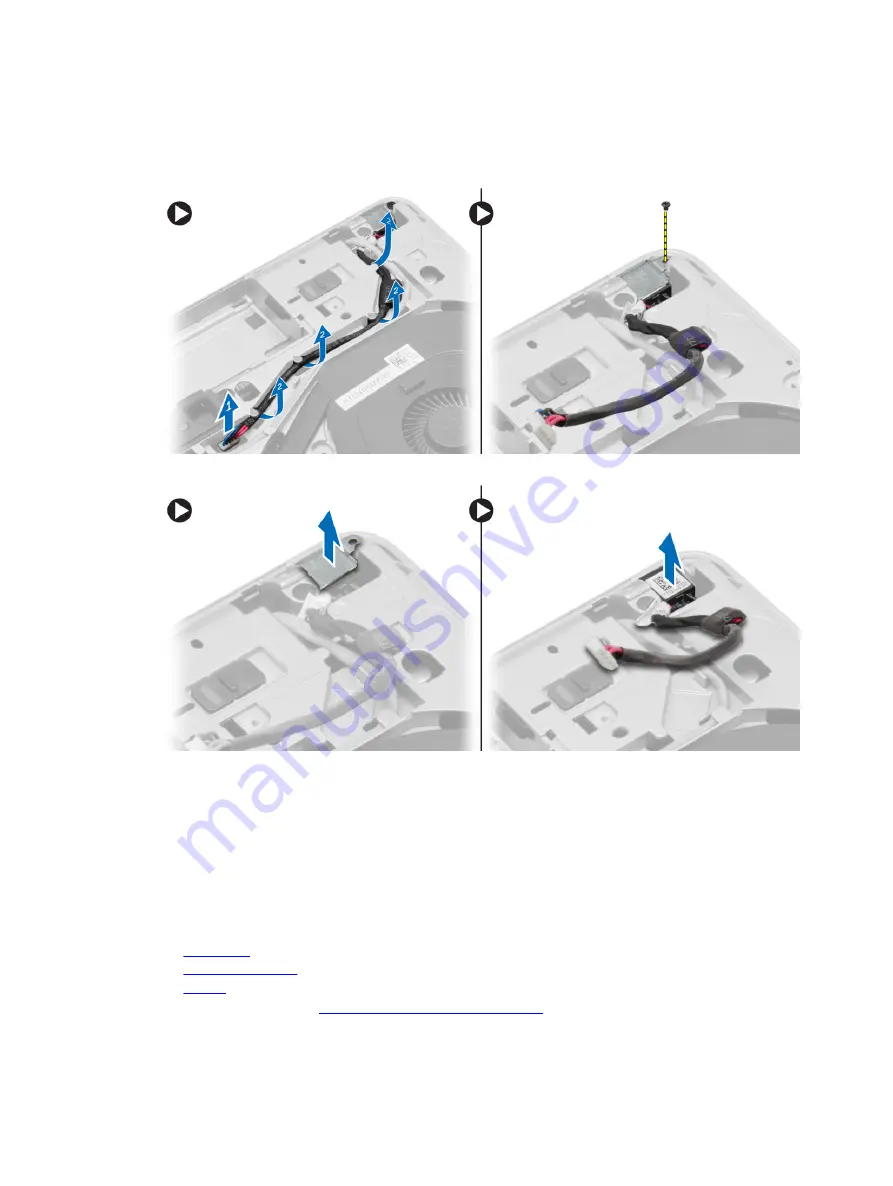
Perform the following steps as shown in the illustration:
a. Disconnect the power-connector cable from the system board.
b. Release the power-connector cable from the routing channel.
c. Remove the screw that secures the power-connector bracket to the computer.

4.

Lift the power-connector bracket from the computer. Lift the power connector from the computer.

Installing the Power Connector

1.

Align the power connector to its position in the computer.

2.

Place the power-connector bracket on the power connector.

3.

Tighten the screw to secure the power-connector bracket to the computer.

4.

Route the cable through the routing channel.

5.

Connect the cable to the system board.

6.

Install:
a.

base cover

b.

base-corner cover

 (right)

c.

battery

7.

Follow the procedures in 

After Working Inside Your Computer

.

Содержание Precision M2800

Страница 1: ...Dell Precision M2800 Owner s Manual Regulatory Model P29F Regulatory Type P29F001 ...

Страница 2: ...dica potenciais danos no equipamento lesões corporais ou mesmo morte Copyright 2014 Dell Inc Todos os direitos reservados Este produto está protegido por leis de copyright e propriedade intelectual dos EUA e internacionais Dell e o logótipo da Dell são marcas comerciais da Dell Inc nos Estados Unidos e ou noutras jurisdições Todas as outras marcas e nomes aqui mencionados podem ser marcas comercia...

Страница 3: ...ing the Base Corner Covers 17 Installing the Base Corner Covers 18 Removing the Memory 19 Installing the Memory 19 Removing the Hard Drive 19 Installing the Hard Drive 21 Removing the Optical Drive 21 Installing the Optical Drive 22 Removing the Wireless Local Area Network WLAN Card 22 Installing the WLAN Card 23 Removing the Wireless Wide Area Network WWAN Card 23 Installing the WWAN Card 23 Remo...

Страница 4: ...y 48 Removing the Display Bezel 49 Installing the Display Bezel 50 Removing the Display Panel 51 Installing the Display Panel 53 Removing the Display Hinges 54 Installing the Display Hinges 54 Removing the Camera 55 Installing the Camera 55 3 Configuração do sistema 57 Sequência de arranque 57 Teclas de navegação 57 Opções da configuração do sistema 58 Actualizar o BIOS 67 Palavra passe do sistema...

Страница 5: ...6 Contactar a Dell 81 ...

Страница 6: ......

Страница 7: ...ção de problemas e algumas reparações simples conforme autorizado na documentação do produto ou como orientado pelo serviço de assistência on line ou por telefone e pela equipa de suporte Os danos causados por assistência não autorizada pela Dell não são abrangidos pela garantia Leia e siga as instruções sobre segurança fornecidas com o produto AVISO Para evitar descargas electrostáticas ligue se ...

Страница 8: ...ã e vire o computador ao contrário numa superfície plana NOTA Para evitar danificar a placa do sistema tem de remover a bateria principal antes de realizar a assistência ao computador 7 Retire a bateria principal 8 Vire o computador ao contrário colocando o para cima 9 Abra o ecrã 10 Prima o botão de alimentação para ligar a placa de sistema à terra AVISO Para evitar choques eléctricos desligue se...

Страница 9: ...Encerrar No Windows 7 1 Clique em Iniciar 2 Clique em Encerrar ou 1 Clique em Iniciar 2 Clique na seta no canto inferior direito do menu Iniciar conforme ilustrado abaixo e em seguida clique em Encerrar 2 Certifique se de que o computador e todos os dispositivos anexados se encontram desligados Se o computador e os dispositivos a estes ligados não se tiverem desligado automaticamente quando encerr...

Страница 10: ...r de portas ou uma base de multimédia e volte a colocar todas as placas como por exemplo uma ExpressCard 2 Ligue todos os cabos de telefone ou de rede ao computador AVISO Para ligar um cabo de rede ligue em primeiro lugar o cabo ao dispositivo de rede e em seguida ligue o ao computador 3 Volte a colocar a bateria 4 Ligue o computador e todos os dispositivos anexados às respectivas tomadas eléctric...

Страница 11: ...putador Ferramentas recomendadas Os procedimentos descritos neste documento podem requerer as seguintes ferramentas Chave de parafusos de ponta chata pequena Chave de parafusos Phillips Instrumento aguçado em plástico System Overview Figure 1 Back View Back Cover Removed 1 heat sink assembly 2 hard drive 3 memory 4 SD card slot ...

Страница 12: ...re 2 Top View Keyboard and Palmrest Assembly removed 1 WiFi switch board 2 speaker 3 ExpressCard cage 4 system board 5 speaker 6 hard drive bay 7 VGA board 8 display assembly Removing the Secure Digital SD Card 1 Follow the procedures in Before Working Inside your computer 2 Press in on the SD card to release it from the computer Slide the SD card out of the computer ...

Страница 13: ...r Computer Removing the ExpressCard 1 Follow the procedures in Before Working Inside Your Computer 2 Press in on the ExpressCard to release it from the computer Slide the ExpressCard out of the computer Installing the ExpressCard 1 Slide the ExpressCard in its slot until it clicks in place 2 Follow the procedures in After Working Inside Your Computer ...

Страница 14: ...Removing the Battery 1 Follow the procedures in Before Working Inside your computer 2 Slide the release latches to unlock the battery ...

Страница 15: ...3 Flip the battery out of the computer Installing the Battery 1 Slide the battery into its slot until it clicks into place 2 Follow the procedures in After Working Inside Your Computer ...

Страница 16: ...Removing the Base Cover 1 Follow the procedures in Before Working Inside your computer 2 Remove the screws that secure the base cover to the computer ...

Страница 17: ... the screw holes on the computer 2 Tighten the screws to secure the base cover to the computer 3 Install the battery 4 Follow the procedures in After Working Inside Your Computer Removing the Base Corner Covers 1 Follow the procedures in Before Working Inside your computer 2 Remove the battery 3 Remove the base cover ...

Страница 18: ...e corner cover lift and remove it from the computer Installing the Base Corner Covers 1 Place the left and right base corner covers to align with the screw holes on the computer 2 Tighten the screws to secure the base corner covers to the computer 3 Install a base cover b battery 4 Follow the procedures in After Working Inside Your Computer ...

Страница 19: ...he memory module from its connector on the system board Installing the Memory 1 Insert the memory into the memory socket 2 Press the securing clips to secure the memory module to the system board 3 Install a base cover b battery 4 Follow the procedures in After Working Inside Your Computer Removing the Hard Drive 1 Follow the procedures in Before Working Inside Your Computer 2 Remove the battery ...

Страница 20: ... computer Slide the hard drive out of the computer 4 Remove the screw that secures the hard drive caddy to the hard drive Remove the hard drive caddy from the hard drive 5 Flex the hard drive isolation Peel off the hard drive isolation from the hard drive ...

Страница 21: ...e hard drive to the computer 6 Install the battery 7 Follow the procedures in After Working Inside Your Computer Removing the Optical Drive 1 Follow the procedures in Before Working Inside Your Computer 2 Remove the battery 3 Press the optical drive latch to release the optical drive and pull the optical drive from the computer 4 Remove the screw that secures the optical drive latch to the optical...

Страница 22: ...ve latch bracket 4 Tighten the screws to secure the optical drive latch to the optical drive latch bracket 5 Slide the optical drive into the drive bay 6 Press the optical drive latch to secure the optical drive 7 Install the battery 8 Follow the procedures in After Working Inside Your Computer Removing the Wireless Local Area Network WLAN Card 1 Follow the procedures in Before Working Inside Your...

Страница 23: ...in Before Working Inside Your Computer 2 Remove a battery b base cover 3 Perform the following steps as shown in the illustration a Disconnect the antenna cables from the WWAN card b Remove the screw that secures the WWAN card to the computer c Remove the WWAN card from the computer Installing the WWAN Card 1 Place the WWAN card in its slot in the system board 2 Press the WWAN card down and tighte...

Страница 24: ...t to the computer 4 Lift the network connector bracket from the computer Lift the network connector from the computer Installing the Network Connector 1 Align the network connector to its position on the computer 2 Place the network connector bracket on the network connector 3 Tighten the screw to secure the network connector bracket to the computer 4 Route the cable through the routing channel 5 ...

Страница 25: ...e the coin cell from the computer Installing the Coin Cell Battery 1 Place the coin cell battery in its slot 2 Connect the coin cell battery cable to the system board 3 Install a base cover b battery 4 Follow the procedures in After Working Inside Your Computer Removing the Power Connector 1 Follow the procedures in Before Working Inside Your Computer 2 Remove a battery b base corner cover right c...

Страница 26: ... from the computer Lift the power connector from the computer Installing the Power Connector 1 Align the power connector to its position in the computer 2 Place the power connector bracket on the power connector 3 Tighten the screw to secure the power connector bracket to the computer 4 Route the cable through the routing channel 5 Connect the cable to the system board 6 Install a base cover b bas...

Страница 27: ... the following steps as shown in the illustration a Slide the heat sink assembly b Lift the heat sink assembly from the computer Installing the Heat Sink Assembly 1 Slide the heat sink assembly to its position on the system board 2 Tighten the screws to secure the heat sink assembly to the system board 3 Connect the fan cable to the system board 4 Install a base cover b battery 5 Follow the proced...

Страница 28: ...essor from the computer Installing the Processor 1 Align the notches on the processor and the socket and insert the processor into the socket 2 Rotate the processor cam lock in a clockwise direction 3 Install a heatsink b base cover c battery 4 Follow the procedures in After Working Inside Your Computer Removing the Keyboard 1 Follow the procedures in Before Working Inside Your Computer 2 Remove t...

Страница 29: ...he screws that secure the keyboard to the palmrest assembly lift and flip the keyboard to access the keyboard cable 5 Disconnect the keyboard cable from the system board Installing the Keyboard 1 Connect the keyboard cable to the system board 2 Slide the keyboard into its compartment and until it clicks into place 3 Tighten the screws to secure the keyboard to the palmrest assembly ...

Страница 30: ...procedures in After Working Inside Your Computer Removing the Palmrest Assembly 1 Follow the procedures in Before Working Inside Your Computer 2 Remove a SD card b ExpressCard c battery d keyboard e display hinge cap f base cover g base corner covers 3 Remove the screws that secure the palmrest assembly to the base of the computer ...

Страница 31: ...4 Flip the computer and remove the screws that secure the palmrest assembly to the computer ...

Страница 32: ...5 Disconnect the following cables a fingerprint reader b touchpad c power button ...

Страница 33: ...e screws to secure the palmrest assembly to the computer 3 Connect the following cables a power button b touchpad c fingerprint reader 4 Flip the computer and tighten the screws to secure the palmrest assembly to the base of the computer 5 Install a base corner covers b base cover c display hinge cap d keyboard e battery f ExpressCard g SD card 6 Follow the procedures in After Working Inside Your ...

Страница 34: ...ct the cable from the system board b Remove the screw that secures the WiFi switch board and lift it from the computer Installing the WiFi Switch Board 1 Place the WiFi switch board in its slot 2 Tighten the screw to secure the WiFi switch board to the computer 3 Connect the cable to the system board 4 Install a palmrest assembly b base cover c base corner covers d display hinge cap e keyboard f b...

Страница 35: ...mbly 3 Remove the screws that secure the VGA board to the computer and remove it from its connector Installing the VGA Board 1 Insert the VGA board in its slot 2 Tighten the screws to secure the VGA board to the computer 3 Install a palmrest assembly b base corner covers c base cover d display hinge cap e keyboard f battery g ExpressCard h SD card 4 Follow the procedures in After Working Inside Yo...

Страница 36: ... screws that secure the ExpressCard cage to the computer Remove the ExpressCard cage from the computer Installing the ExpressCard Cage 1 Place the ExpressCard cage in its slot 2 Tighten the screws to secure the ExpressCard cage to the computer 3 Install a palmrest assembly b base corner covers c base cover d display hinge cap e keyboard f battery g ExpressCard h SD card 4 Follow the procedures in ...

Страница 37: ...side Your Computer 2 Remove a SD card b ExpressCard c battery d keyboard e hard drive f optical drive g display hinge cap h base cover i base corner covers j power connector k coin cell l memory m WLAN card n WWAN card o heatsink p processor q VGA board r ExpressCard cage ...

Страница 38: ...3 Perform the following steps as shown in the illustration a Disconnect the WiFi switch from the system board b Disconnect the speaker cables from the system board ...

Страница 39: ...4 Remove the screws that secure the system board to the computer ...

Страница 40: ... the computer Installing the System Board 1 Place the system board to align with the ports on the computer 2 Tighten the screws to secure the system board 3 Connect the following cables to the system board a speaker b WiFi switch ...

Страница 41: ...Card r SD card 5 Follow the procedures in After Working Inside Your Computer Removing the Speakers 1 Follow the procedures in Before Working Inside Your Computer 2 Remove a SD card b ExpressCard c battery d keyboard e hard drive f optical drive g display hinge cap h base cover i base corner covers j palmrest assembly k power connector l coin cell m memory n WLAN card o WWAN card p heatsink q proce...

Страница 42: ...3 Remove the speaker cable from the routing channels Remove the screws that secure the speakers to the computer ...

Страница 43: ...peakers from the computer Installing the Speakers 1 Align the speakers in its position on the computer and route the speaker cable in the routing channels on the computer 2 Tighten the screws to secure the speakers ...

Страница 44: ...ard t SD card 4 Follow the procedures in After Working Inside Your Computer Removing the Display Hinge Cap 1 Follow the procedures in Before Working Inside Your Computer 2 Remove the battery 3 Remove the screws that secure the display hinge cap to the computer and remove the display hinge cap from the computer Installing the Display Hinge Cap 1 Align the display hinge cap with the screw holes 2 Ti...

Страница 45: ...mbly 1 Follow the procedures in Before Working Inside your computer 2 Remove a battery b display hinge cap c base cover d base corner covers 3 Disconnect the antenna cables connected to the WLAN card and release it from the routing channel Disconnect the camera cable from the system board ...

Страница 46: ...4 Disconnect the LVDS cable and release the LVDS cable and camera cable from the routing channel Remove them from the computer ...

Страница 47: ...5 Remove the screws that secure the display assembly to the computer ...

Страница 48: ...play assembly 3 Route the LVDS cable and the camera cable through the routing channel 4 Route the antenna cables through the routing channel 5 Connect the antenna cables to the WLAN card on the computer 6 Connect the camera cable to the computer 7 Install a base corner covers b base cover c display hinge cap d battery 8 Follow the procedures in After Working Inside Your Computer ...

Страница 49: ...lay Bezel 1 Follow the procedures in Before Working Inside Your Computer 2 Remove a battery b display hinge cap c base cover d base corner covers e display assembly 3 Pry up along the edges to release the display bezel ...

Страница 50: ...arting from the top corner press on the display bezel and work around the entire bezel until it clicks onto the display assembly 3 Press on the left and right edges of the display bezel 4 Install a display assembly b base corner covers c base cover d display hinge cap e battery 5 Follow the procedures in After Working Inside Your Computer ...

Страница 51: ... the procedures in Before Working Inside Your Computer 2 Remove a battery b display hinge cap c base cover d base corner covers e display assembly f display bezel 3 Remove the screws that secure the display panel to the display assembly ...

Страница 52: ...4 Flip the display panel over ...

Страница 53: ...Panel 1 Connect the LVDS cable and stick the LVDS cable connector tape 2 Flip the display and place it in the display assembly 3 Tighten the screws to secure the display panel to the display assembly 4 Install a display bezel b display assembly c base corner covers d base cover e display hinge cap f battery 5 Follow the procedures in After Working Inside Your Computer ...

Страница 54: ...on a Remove the screws that secure the display hinges to the display assembly b Remove the display hinges from the computer Installing the Display Hinges 1 Place the display hinges in its location on the computer 2 Tighten the screws to secure the display hinges to the display assembly 3 Install a display panel b display bezel c display assembly d base corner covers e base cover f display hinge ca...

Страница 55: ...ect the camera cable b Remove the screw that secures the camera module c Lift the camera module from the computer Installing the Camera 1 Place the camera module in its slot in the computer 2 Tighten the screw to secure the camera to the display assembly 3 Connect the camera cable 4 Install a display bezel b display assembly c battery 5 Follow the procedures in After Working Inside Your Computer ...

Страница 56: ......

Страница 57: ...rece o logótipo Dell pode Aceder à Configuração do Sistema premindo a tecla F2 Abrir um menu de arranque único premindo a tecla F12 O menu de arranque único apresenta os dispositivos a partir dos quais pode arrancar o computador incluindo a opção de diagnóstico As opções do menu de arranque são Removable Drive Unidade amovível se existir STXXXX Drive Unidade STXXXX NOTA XXX representa o número da ...

Страница 58: ... da Configuração do Sistema Opções da configuração do sistema NOTA Dependendo do computador e dos dispositivos instalados os itens listados nesta secção podem ou não aparecer Tabela 2 General Geral Opção Descrição System Information Esta secção lista as principais funcionalidades de hardware do seu computador Informações sobre o sistema Memory Information Informações da memória Processor Informati...

Страница 59: ...d Desactivado Enabled Activado Enabled w PXE Activado com PXE predefinição Parallel Port Permite lhe definir e configurar a forma como a porta paralela funciona na estação de ancoragem Pode definir a porta paralela para Disabled Desactivado AT predefinição PS2 ECP Serial Port Identifica e define as definições da porta série É possível definir a porta série como Disabled Desactivado COM1 predefiniç...

Страница 60: ...ório SMART USB Configuration Permite lhe definir a configuração USB As opções são Enable Boot Support Activar suporte de arranque Enable External USB Port Activar porta USB externa Predefinição ambas as opções estão activadas USB PowerShare Permite lhe configurar o comportamento da funcionalidade USB PowerShare A opção está desactivada por predefinição Enable USB PowerShare Activar USB PowerShare ...

Страница 61: ...ecção contra queda livre da unidade de disco rígido Predefinição todos os dispositivos estão activados Pode seleccionar se pretende activar ou desactivar o cartão multimédia As opções são Enable Media Card Activar cartão multimédia predefinição Disable Media Card Desactivar cartão multimédia Tabela 4 Vídeo Opção Descrição LCD Brightness Permite lhe definir o brilho do painel quando o sensor ambien...

Страница 62: ...o predefinição Reboot bypass Ignorar reinício Password Change Permite lhe activar a permissão para desactivar as palavras passe de sistema e da unidade de disco rígido quando a palavra passe de administrador está definida Allow Non Admin Password Changes Permitir alterações de palavra passe não de administrador predefinição Non Admin Setup Changes Permite lhe determinar se as alterações à configur...

Страница 63: ...nho Opção Descrição Multi Core Support Este campo especifica se o processador tem activados todos os núcleos ou apenas um O desempenho de algumas aplicações melhora com a utilização de núcleos adicionais Esta opção está activada por predefinição Permite lhe activar ou desactivar o suporte para núcleos múltiplos do processador As opções são All Todos predefinição 1 2 Intel SpeedStep Permite lhe act...

Страница 64: ... S5 only Activado apenas em S5 Enabled in S4 and S5 Activado em S4 e S5 USB Wake Support Permite lhe activar os dispositivos USB para reactivarem o computador a partir do modo de espera A opção está desactivada Enable USB Wake Support Activar suporte para activação por USB Wireless Radio Control Permite lhe controlar o rádio WLAN e WWAN As opções são Control WLAN Radio Controlo de rádio WLAN Contr...

Страница 65: ...press Charge Carregamento expresso predefinição Module Bay Battery Charge Configuration Permite lhe definir como carregar a bateria à velocidade padrão As opções são Standard Padrão Express Charge Carregamento expresso predefinição NOTA Desactive o Advanced Battery Charge Mode Modo avançado de carregamento da bateria para poder activar esta opção Intel R Smart Connect Technology Permite lhe activa...

Страница 66: ...EBx Hotkey Permite lhe activar a função de tecla de atalho MEBx se for necessário A opção está activada por predefinição Tabela 10 Virtualization Support Suporte de virtualização Opção Descrição Virtualization Especifica se um Monitor de máquina virtual VMM pode utilizar as capacidades de hardware adicionais fornecidas pela tecnologia Intel Virtualization Enable Intel Virtualization Technology Act...

Страница 67: ...ite limpar o registo Thermal Events Apresenta os eventos térmicos e permite limpar o registo Power Events Apresenta os eventos de alimentação e permite limpar o registo Actualizar o BIOS Recomenda se que actualize o BIOS configuração do sistema se substituir a placa de sistema ou se estiver disponível uma actualização No caso dos portáteis certifique se de que a bateria do computador está totalmen...

Страница 68: ...o BIOS actualizadas no computador Siga as instruções apresentadas no ecrã Palavra passe do sistema e de configuração Pode criar uma palavra passe do sistema e uma palavra passe de configuração para proteger o computador Tipo de palavra passe Descrição Palavra passe do sistema A palavra passe que tem de introduzir para iniciar sessão no sistema Palavra passe de configuração A palavra passe que tem ...

Страница 69: ...one Setup Password Palavra passe de configuração digite a palavra passe do sistema e prima Enter ou Tab Aparece uma mensagem a solicitar que volte a introduzir a palavra passe do sistema 6 Digite a palavra passe de configuração que introduziu antes e clique em OK 7 Prima Esc e uma mensagem pedir lhe á que guarde as alterações 8 Prima Y para guardar as alterações O computador é reiniciado Eliminar ...

Страница 70: ...asse do sistema e ou de configuração volte a introduzir a nova palavra passe quando for solicitado Se eliminar a palavra passe do sistema e ou de configuração confirme a eliminação quando lhe for solicitado 5 Prima Esc e uma mensagem pedir lhe á que guarde as alterações 6 Prima Y para guardar as alterações e sair da Configuração do Sistema O computador é reiniciado ...

Страница 71: ...ns de estado que indicam se os testes foram concluídos com sucesso Ver mensagens de erro que informam sobre problemas verificados durante os testes AVISO Utilize o diagnóstico do sistema para testar apenas o seu computador Se for utilizado com outros computadores este programa pode causar resultados inválidos ou mensagens de erro NOTA Alguns testes de dispositivos específicos requerem a interacção...

Страница 72: ...o Tabela 15 Luzes LED LED de armazenament o LED de alimentação LED sem fios Descrição da avaria Intermitente Fixo Fixo Ocorreu uma possível falha do processador Fixo Intermitente Fixo Os módulos de memória são detectados mas foi encontrado um erro Intermitente Intermitente Intermitente Ocorreu uma falha da placa de sistema Intermitente Intermitente Fixo Ocorreu uma possível falha na placa gráfica ...

Страница 73: ...não suportado que não é da marca Dell ligado ao computador portátil Luz âmbar intermitente com luz branca fixa alternadamente Falha temporária da bateria com adaptador de CA presente Luz âmbar intermitente constante Falha fatal da bateria com adaptador de CA presente Luz desligada Bateria em modo de carga total com adaptador de CApresente Luz branca acesa Bateria em modo de carregamento com adapta...

Страница 74: ......

Страница 75: ...on Chipset Mobile Intel QM87 Express Chipset DRAM bus width 64 bit Flash EPROM SPI 32 Mbits 64 Mbits PCIe bus 100 MHz External Bus Frequency PCIe Gen2 5GT s Table 17 Processor Feature Specification Types Intel Core i5 i7series L3 cache 3 MB 4MB and 6 MB Table 18 Memory Feature Specification Memory connector Two SODIMM slots Memory capacity 4 GB or 8 GB Memory type DDR3L SDRAM 1600 MHz Minimum memo...

Страница 76: ...VGA one HDMI NOTE Support two DP DVI ports through Docking station Table 21 Camera Features Specification Camera Resolution 1280 x 720 pixels Video Resolution maximum 1280 x 720 pixels Diagonal viewing angle 74 Table 22 Communications Features Specification Network adapter 10 100 1000 Mb s Ethernet RJ 45 Wireless internal wireless local area network WLAN and wireless wide area network WWAN Table 2...

Страница 77: ...idth 360 00 mm 14 17 inches 360 00 mm 14 17 inches Diagonal 396 24 mm 15 60 inches 396 24 mm 15 60 inches Active area X Y 384 mm X 258 mm 15 12 inches X 10 16 inches 344 23 mm X 193 53 mm 13 55 inches X 7 61 inches Maximum resolution 1920 X 1080 1366 X 768 Maximum Brightness 300 nits 200 nits Refresh rate 60 Hz 60 Hz Minimum Viewing Angles Horizontal 60 40 40 Vertical 50 10 30 Pixel pitch 0 179 0 ...

Страница 78: ...erature range Operating 0 C to 50 C 32 F to 158 F Non Operating 20 C to 65 C 4 F to 149 F Coin cell battery 3 V CR2032 lithium coin cell Table 29 AC Adapter Feature Specification Type 130 W Input voltage 100 VAC to 240 VAC Input current maximum 2 5 A Input frequency 50 Hz to 60 Hz Output current 6 7 A Rated output voltage 19 5 1 0 VDC Temperature range Operating 0 C to 40 C 32 F to 104 F Non Opera...

Страница 79: ... C 32 F to 95 F Storage 40 C to 65 C 40 F to 149 F Relative humidity maximum Operating 10 to 90 non condensing Storage 5 to 95 non condensing Altitude maximum Operating 15 2 m to 3048 m 50 to 10 000 ft 0 to 35 C Non Operating 15 24 m to 10 668 m 50 ft to 35 000 ft Airborne contaminant level G1 as defined by ISA 71 04 1985 ...

Страница 80: ......

Страница 81: ...varia de acordo com o país e com o produto e alguns serviços podem não estar disponíveis na sua área Para contactar a Dell relativamente a vendas suporte técnico ou apoio a clientes 1 Visite dell com support 2 Seleccione a categoria de suporte pretendida 3 Seleccione o seu país ou região no menu pendente Choose a Country Region Escolher um país região na parte superior da página 4 Seleccione a lig...

Отзывы: