background image

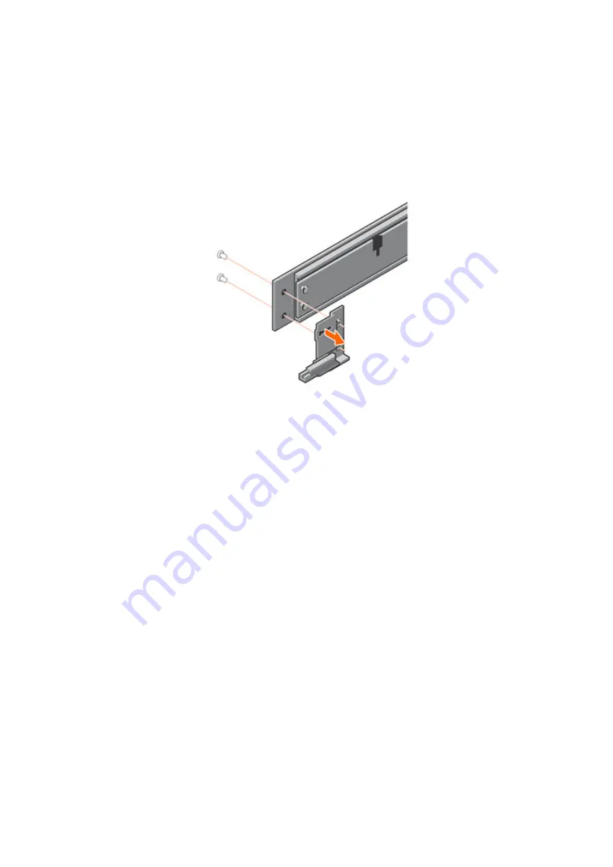
Remove the original CMA brackets

About this task

The system rails may ship with CMA brackets already attached. If the brackets are attached, they must be removed.

Steps

1. Remove the two screws holding the CMA bracket to the rail.

Figure 74. Remove the original CMA bracket

2. Repeat the previous step for the second rail.

Attach the new CMA brackets

About this task

The brackets are labeled left and right, and cannot be interchanged. The top of each bracket is labeled 

Up

.

Steps

1. Use the included screws to install the outer bracket to the rail.

138

Replace the Rail Kit

Содержание PowerProtect DD6900

Страница 1: ...Dell EMC PowerProtect DD6900 Field Replacement Unit and Customer Replacement Unit Guide 7 X August 2021 Rev 07 ...

Страница 2: ...the hard drive 20 Install the front bezel 20 Verify the replacement drive 21 Chapter 3 Replace a Cache Tier Disk 23 Chapter 4 Replace a Fan 24 Identify a failed fan 24 Extend the system from the cabinet 25 Remove the system cover 25 Remove the cooling fan 26 Install the cooling fan 26 Install the system cover 27 Slide the system into the cabinet 28 Verify the replacement fan 29 Restore the HA conf...

Страница 3: ... module 51 Installing the air shroud 52 Install the system cover 53 Slide the system into the cabinet 53 Reconnect and power on the system 54 Verify the replacement DIMM 54 Restore the HA configuration 55 Chapter 8 Replace a PCIe HBA SAS FC or NIC 57 Identify the failed PCIe HBA SAS FC or NIC 57 Shut down and disconnect the system 58 Extend the system from the cabinet 59 Remove the system cover 59...

Страница 4: ... Restore the HA configuration 83 Chapter 11 Replace the HBA330 SAS Controller 84 Verify the status of the HBA330 84 Shut down and disconnect the system 85 Extend the system from the cabinet 85 Remove the system cover 86 Remove expansion card riser 1 87 Remove the integrated storage controller card 87 Install the integrated storage controller card 88 Install expansion card riser 1 89 Install the sy...

Страница 5: ...essor and heat sink module 114 Remove the system board 115 Install the system board 116 Install a processor and heat sink module 116 Install the memory module 117 Install the integrated storage controller card 118 Install expansion card riser 1 119 Install expansion card riser 2 120 Install expansion card riser 3 120 Install the cooling fan assembly 121 Installing the air shroud 122 Install the sy...

Страница 6: ...ing the rails 137 Remove the original CMA brackets 138 Attach the new CMA brackets 138 Install the rails 140 Secure the rail assemblies to the cabinet 141 Install the system in the cabinet 142 Install the front bezel 144 Install the CMA arms 144 Slide the system into the cabinet 148 Reconnect and power on the system 148 Restore the HA configuration 149 6 Contents ...

Страница 7: ...y module 51 22 Installing a memory module 52 23 Installing the air shroud 52 24 Slot numbering 57 25 Remove the system cover 60 26 Removing the expansion card from expansion card riser 1 61 27 Removing the expansion card from expansion card riser 2 61 28 Removing the expansion card from expansion card riser 3 62 29 Installing expansion card into expansion card riser 1 63 30 Installing expansion ca...

Страница 8: ...nstalling the integrated storage controller card 118 61 Installing the integrated storage controller card cable 119 62 Installing expansion card riser 1 119 63 Installing expansion card riser 2 120 64 Installing expansion card riser 3 121 65 Installing the cooling fan assembly 122 66 Installing the air shroud 123 67 Removing the front bezel 131 68 Installing the front bezel 132 69 Sliding rail ass...

Страница 9: ...84 Install the first separator 145 85 Install the first arm 145 86 Close the first arm 146 87 Install the second separator 146 88 Install the second arm 147 89 Close the second arm 147 Figures 9 ...

Страница 10: ...1 Communications settings 14 2 NIC LED states 44 3 Memory mapping 46 4 Slot assignments 58 Tables 10 Tables ...

Страница 11: ...tial damage to hardware or loss of data and tells you how to avoid the problem WARNING A WARNING indicates a potential for property damage personal injury or death 2020 2020 Dell Inc or its subsidiaries All rights reserved Dell EMC and other trademarks are trademarks of Dell Inc or its subsidiaries Other trademarks may be trademarks of their respective owners ...

Страница 12: ...ps 2 with a 4 to 6 inch blade and a magnetic tip Phillips 2 with a 12 in or longer blade and magnetic tip Flat head with a 3 16 in blade Flat head with a 1 4 in blade Torx T8 Torx T10 Torx T30 with adjustable torque setting Torque Flashlight free standing for single person installations Roll of 5 8 inch Velcro cable tie material 3M Scotchmate SJ 3401 or similar Null modem cable with DB 9 female co...

Страница 13: ...ents by yourself A DD6900 system weighs up to 63 05 lbs 28 6 kg CAUTION PowerProtect systems are heavy Use at least two people or a mechanical lift to move any system To comply with applicable safety emission and thermal requirements covers must not be removed and all bays must be fitted with plug in modules For ESD protection Dell EMC recommends that you wear a suitable antistatic wrist or ankle ...

Страница 14: ...vice personnel attempt to use the serial port to access the system Figure 1 Maintenance connections 1 Ethernet port 2 Serial port COM 1 Steps Verify with the customer whether the system uses a serial connection or SOL and follow one of the procedures below as required Establish a serial connection to the serial port Steps 1 Connect a serial console cable from the management station or laptop to th...

Страница 15: ...ure can be completed by a customer CRU or a Dell EMC or partner technician FRU Component Hot swappable CRU FRU Bezel Y CRU Front disk OS and cache Y CRU Power supply Y CRU Cable management accessory Y CRU Fan Y CRU DIMM N CRU Network daughter card N CRU PCIe HBA PCIe HBA mini card N CRU NVRAM N FRU HBA330 N CRU TPM N FRU System board N FRU CPU heatsink N FRU Rail kit N CRU Prepare HA systems for c...

Страница 16: ...ss at the time of the failover require a manual restart CIFS NDMP VTL After a failover jobs that were in progress at the time of the failover using the following protocols will resume automatically after the failover DD Boost over FC DD Boost over IP NFS Replication Data movement to Cloud Tier 4 Run the ha offline command on the node where the maintenance activity will be performed to prevent disr...

Страница 17: ...em Topics Identify a failed OS disk Remove the front bezel to access front panel hard drives Remove a hard drive Install the hard drive Install the front bezel Verify the replacement drive Identify a failed OS disk Prerequisites Establish a connection to the system as described in Establish a serial management connection to the PowerProtect system on page 14 About this task Complete the following ...

Страница 18: ...ich are part of the actual output alerts show current sysadmin localhost alerts show current Object Message Enclosure 1 Disk 4 Cause NA EVT STORAGE 00031 Disk has a hardware fault and may need to be replaced There are 1 active alerts 3 Match the slot number of the failed disk from the alerts show current output to the physical location of the disk 4 Run the disk beacon command on the failed disk t...

Страница 19: ... 1 Press the release button to open the hard drive release handle 2 Holding the handle slide the hard drive out of the hard drive slot Figure 4 Removing a hard drive 3 If you are not replacing the hard drive immediately insert a hard drive blank in the empty hard drive slot to maintain proper system cooling Replace an Operating System Disk 19 ...

Страница 20: ...nto the hard drive slot and slide until the hard drive connects with the backplane 3 Close the hard drive release handle to lock the hard drive in place Figure 5 Installing a hard drive Install the front bezel Steps 1 Align and insert the right end of the bezel onto the system 2 Press the release button and fit the left end of the bezel onto the system 3 Lock the bezel by using the key 20 Replace ...

Страница 21: ...s task Complete the following tasks to verify the replacement disk Steps 1 Verify the drive fault LED on the left control panel at the front of the system is off Figure 7 Drive fault LED 2 In the CLI press Ctrl C to turn off the disk beacon Replace an Operating System Disk 21 ...

Страница 22: ...ify all the disks appear correctly 4 Use the alerts show current or alerts show current detailed command alerts show current No active alerts 5 Run the disk show state command to verify the disk rebuild status 22 Replace an Operating System Disk ...

Страница 23: ...e front of the chassis This CRU can be completed with the system powered on Cache Tier disks are not RAID protected so no disk rebuild is required CAUTION This procedure applies to single node systems only For HA pairs the Cache Tier disks are located in an FS25 SSD shelf 3 Replace a Cache Tier Disk 23 ...

Страница 24: ...tify the failed fan Steps 1 Use the alerts show current or alerts show current detailed command that will include messages indicating fan loss or fan failure NOTE The sample output below only includes the alert object and alert message It does not include the columns for the alert ID post time severity and alert class which are part of the actual output alerts show current Object Message Enclosure...

Страница 25: ...n the left and right sides of the system Pull the slam latches up to release the system from the cabinet If the slam latches do not disengage loosen the screw under each latch 2 Using the slam latches pull the system from the cabinet until the rails lock in the extended position Remove the system cover Steps 1 Using a flat or a Phillips head screwdriver rotate the latch release lock counter clockw...

Страница 26: ...ss the release tab and lift the cooling fan out of the cooling fan assembly Figure 9 Removing cooling fan Install the cooling fan Steps Holding the release tab align the connector at the base of the cooling fan with the connector on the system board 26 Replace a Fan ...

Страница 27: ...left inside the system Steps 1 Align the tabs on the system cover with the guide slots on the system 2 Push the system cover latch down The system cover slides forward the tabs on the system cover engage with the guide slots on the system and the system cover latch locks into place 3 Using a flat or Phillips head screwdriver rotate the latch release lock clockwise to the locked position Replace a ...

Страница 28: ...f the cabinet push the system inward until the lock levers click into place 2 Push the blue slide release lock tabs forward on both rails and slide the system into the cabinet The slam latches will engage to secure the system in the cabinet 28 Replace a Fan ...

Страница 29: ... current No active alerts Restore the HA configuration Bring the HA configuration back online after completing the maintenance activity About this task For single node systems skip these steps Steps 1 Run the ha online command on the node where the maintenance was performed to bring the HA configuration back online ha online The operation will reboot this node Do you want to proceed yes no no yes ...

Страница 30: ...3 Optionally run the ha failover command on the current active node to fail the system back to the original active node 30 Replace a Fan ...

Страница 31: ...agement connection to the PowerProtect system on page 14 About this task Complete the following steps to identify the failed power supply Steps 1 Check the LED on the affected power supply unit The power supply handle functions as the LED NOTE If a power supply unit is found to be faulted the LED blinks amber 2 Enter the alerts show current command or alerts show current detailed to display messag...

Страница 32: ...wer supply 1 is the left hand PSU and power supply 2 is the right hand PSU Remove a power supply Prerequisites Follow the safety guidelines listed in Safety instructions on page 13 About this task The technical white paper Servicing and Replacing Power Supplies for DellEMC PowerEdge R940 R740 R740xd Systems with Single and Dual CMA Solutions provides additional details about removing power supplie...

Страница 33: ...into a power outlet CAUTION When connecting the power cable to the PSU secure the cable to the PSU with the strap NOTE When installing hot swapping or hot adding a new PSU wait for 15 seconds for the system to recognize the PSU and determine its status The PSU redundancy may not occur until discovery is complete Wait until the new PSU is discovered and enabled before you remove the other PSU The P...

Страница 34: ...ed to bring the HA configuration back online ha online The operation will reboot this node Do you want to proceed yes no no yes Broadcast message from root Wed Jul 22 17 03 32 2020 The system is going down for reboot NOW This node is changed to online state Node is going down for reboot 2 Run the ha status command to verify that the HA pair is back online and can failover HA System Name datadomain...

Страница 35: ...ment network daughter card Restore the HA configuration Verify the status of the network daughter card Prerequisites Establish a connection to the system as described in Establish a serial management connection to the PowerProtect system on page 14 About this task Complete the following steps to verify the network daughter card requires replacement Steps 1 Use the enclosure show io cards command t...

Страница 36: ...Open the cable management arms 3 Label each of the cables as to their connection location Taking a photograph for reference is also helpful for re connecting the cables 4 Disconnect the AC power cords from the rear of the system 5 Disconnect all network cables from the rear of the system 6 Disconnect all SAS cables from the rear of the system 7 Disconnect the serial console cable Extend the system...

Страница 37: ...nter clockwise to the unlocked position 2 Lift the latch till the system cover slides back and the tabs on the system cover disengage from the guide slots on the system 3 Hold the cover on both sides and lift the cover away from the system Figure 11 Remove the system cover Replace the Network Daughter Card 37 ...

Страница 38: ...ety instructions on page 13 Steps 1 If installed remove expansion cards installed on the riser 2 Disconnect any cables connected to the riser 3 To remove expansion card riser 2 a Using Phillips 2 screwdriver loosen the screws that secure the riser to the system b Press the release tab and holding the riser by its edges lift the riser from the riser connector on the system board 38 Replace the Netw...

Страница 39: ...edges on either side of the touch points and lift to remove it from the connector on the system board 3 Slide the NDC towards the front of the system until the Ethernet connectors are clear of the slot in the back panel Figure 14 Removing the network daughter card Install the network daughter card Steps 1 Orient the NDC so that the Ethernet connectors fit through the slot in the chassis Replace th...

Страница 40: ...network daughter card Install expansion card riser 2 Prerequisites Follow the safety guidelines listed in Safety instructions on page 13 Steps To install expansion card riser 2 a Align the screw and tab on the riser with the screw hole and slot on the system b Lower the riser into the system until the riser connector engages with the connector on the system board c Using Phillips 2 screwdriver tig...

Страница 41: ...w the safety guidelines Ensure that all internal cables are routed correctly and connected and that no tools or extra parts are left inside the system Steps 1 Align the tabs on the system cover with the guide slots on the system 2 Push the system cover latch down The system cover slides forward the tabs on the system cover engage with the guide slots on the system and the system cover latch locks ...

Страница 42: ... blue slide release lock tabs forward on both rails and slide the system into the cabinet The slam latches will engage to secure the system in the cabinet Reconnect and power on the system About this task Complete the following steps to reconnect cables power on the system and reconnect a terminal session 42 Replace the Network Daughter Card ...

Страница 43: ...ower cords to the power supplies NOTE The system may not power on automatically after plugging in the AC power cords 5 If the system does not power on when the AC power cords were reconnected press the power button on the right control panel at the front of the system 6 When the system boots log in as sysadmin Verify the replacement network daughter card About this task Complete the following step...

Страница 44: ...etwork daughter card Verify the network daughter card appears in the list 3 Use the alerts show current or alerts show current detailed command alerts show current No active alerts Restore the HA configuration Bring the HA configuration back online after completing the maintenance activity About this task For single node systems skip these steps Steps 1 Run the ha online command on the node where ...

Страница 45: ...datadomain ha3a p1 emc com 1 active online 3 Optionally run the ha failover command on the current active node to fail the system back to the original active node Replace the Network Daughter Card 45 ...

Страница 46: ...ud Remove the memory module Install the memory module Installing the air shroud Install the system cover Slide the system into the cabinet Reconnect and power on the system Verify the replacement DIMM Restore the HA configuration Identify a failed DIMM Prerequisites Establish a connection to the system as described in Establish a serial management connection to the PowerProtect system on page 14 A...

Страница 47: ... A12 2400 8192 9ASF1G72PZ 2G6D1 213762EF B1 2400 16384 18ASF2G72PDZ 2G6E1 F008613F B2 2400 16384 18ASF2G72PDZ 2G6E1 F0086146 B3 2400 16384 18ASF2G72PDZ 2G6E1 F008613C B4 2400 16384 18ASF2G72PDZ 2G6E1 F0085B81 B5 2400 16384 18ASF2G72PDZ 2G6E1 F008607C B6 2400 16384 18ASF2G72PDZ 2G6E1 20E4CFA4 B7 2400 8192 9ASF1G72PZ 2G6D1 2137500C B8 2400 8192 9ASF1G72PZ 2G6D1 2137635F B9 2400 8192 9ASF1G72PZ 2G6D1...

Страница 48: ...l LED turns off NOTE The system fans still run and NIC port LEDs still flash after running the system poweroff command 2 Open the cable management arms 3 Disconnect the AC power cords from the rear of the system Extend the system from the cabinet Use this procedure to extend the system from the cabinet so that you can remove the system cover to access the internal FRU components or to remove the s...

Страница 49: ...n 2 Lift the latch till the system cover slides back and the tabs on the system cover disengage from the guide slots on the system 3 Hold the cover on both sides and lift the cover away from the system Figure 19 Remove the system cover Removing the air shroud Steps Hold the air shroud at both ends and lift it away from the system Replace a DIMM 49 ...

Страница 50: ...t be installed in any memory socket that is not occupied Remove memory module blanks only if you intend to install memory modules in those sockets Steps 1 Locate the appropriate memory module socket CAUTION Handle each memory module only by the card edges ensuring not to touch the middle of the memory module or metallic contacts 2 Push the ejectors outward on both ends of the memory module socket ...

Страница 51: ...e to the memory module or the memory module socket during installation do not bend or flex the memory module You must insert both ends of the memory module simultaneously 2 Open the ejectors on the memory module socket outward to allow the memory module to be inserted into the socket 3 Align the edge connector of the memory module with the alignment key of the memory module socket and insert the m...

Страница 52: ... tabs on the air shroud with the slots on the system 2 Lower the air shroud into the system until it is firmly seated When firmly seated the memory socket numbers marked on the air shroud align with the respective memory sockets Figure 23 Installing the air shroud 52 Replace a DIMM ...

Страница 53: ...rd the tabs on the system cover engage with the guide slots on the system and the system cover latch locks into place 3 Using a flat or Phillips head screwdriver rotate the latch release lock clockwise to the locked position Slide the system into the cabinet Steps 1 At the front of the cabinet push the system inward until the lock levers click into place 2 Push the blue slide release lock tabs for...

Страница 54: ... AC power cords 4 If the system does not power on when the AC power cords were reconnected press the power button on the right control panel at the front of the system 5 When the system boots log in as sysadmin Verify the replacement DIMM About this task Complete the following steps to verify the replacement DIMM Steps 1 Enter the system show meminfo command to see the top level summary Confirm th...

Страница 55: ... MHz 16384 MB DIMM B9 2666 MHz 8192 MB DIMM B10 2666 MHz 16384 MB DIMM B11 2666 MHz 8192 MB DIMM B12 2666 MHz 16384 MB 3 Check for any new DIMM alerts Restore the HA configuration Bring the HA configuration back online after completing the maintenance activity About this task For single node systems skip these steps Steps 1 Run the ha online command on the node where the maintenance was performed ...

Страница 56: ...datadomain ha3a p1 emc com 1 active online 3 Optionally run the ha failover command on the current active node to fail the system back to the original active node 56 Replace a DIMM ...

Страница 57: ... system Extend the system from the cabinet Remove the system cover Remove an expansion card from an expansion card riser Install expansion card into expansion card riser Install the system cover Slide the system into the cabinet Reconnect and power on the system Verify the PCIe HBA replacement Restore the HA configuration Identify the failed PCIe HBA SAS FC or NIC Steps 1 Enter the alerts show cur...

Страница 58: ...erProtect system on page 14 About this task Complete the following steps to shut down and disconnect the system Steps 1 Stop the system using the system poweroff command to allow the proper shut down of the file system and other system components The power down process takes approximately five minutes to complete The system poweroff command immediately turns the front panel blue LED to amber and i...

Страница 59: ...the cabinet If the slam latches do not disengage loosen the screw under each latch 2 Using the slam latches pull the system from the cabinet until the rails lock in the extended position Remove the system cover Steps 1 Using a flat or a Phillips head screwdriver rotate the latch release lock counter clockwise to the unlocked position 2 Lift the latch till the system cover slides back and the tabs ...

Страница 60: ...pansion card riser Refer to the applicable illustration to aid in removal of the expansion card from the expansion card riser NOTE When removing an expansion card from riser 2 or 3 ensure that the PCIe card holder latch is closed Steps 1 If applicable disconnect the cables from the expansion card 2 Hold the expansion card by its edges and pull the card until the card edge connector disengages from...

Страница 61: ...Figure 26 Removing the expansion card from expansion card riser 1 Figure 27 Removing the expansion card from expansion card riser 2 Replace a PCIe HBA SAS FC or NIC 61 ...

Страница 62: ...E Store the filler bracket for future use Filler brackets must be installed in empty expansion card slots to maintain Federal Communications Commission FCC certification of the system The brackets also keep dust and dirt out of the system and aid in proper cooling and airflow inside the system 3 Hold the card by its edges and align the card edge connector with the expansion card connector on the r...

Страница 63: ...Figure 29 Installing expansion card into expansion card riser 1 Figure 30 Installing expansion card into expansion card riser 2 Replace a PCIe HBA SAS FC or NIC 63 ...

Страница 64: ...s are left inside the system Steps 1 Align the tabs on the system cover with the guide slots on the system 2 Push the system cover latch down The system cover slides forward the tabs on the system cover engage with the guide slots on the system and the system cover latch locks into place 3 Using a flat or Phillips head screwdriver rotate the latch release lock clockwise to the locked position 64 R...

Страница 65: ...e blue slide release lock tabs forward on both rails and slide the system into the cabinet The slam latches will engage to secure the system in the cabinet Reconnect and power on the system About this task Complete the following steps to reconnect cables power on the system and reconnect a terminal session Replace a PCIe HBA SAS FC or NIC 65 ...

Страница 66: ...ystem boots log in as sysadmin Verify the PCIe HBA replacement Steps 1 Use the alerts show current command and confirm that the system has cleared the alert for the failed I O module It may take one to two minutes after the I O module replacement before the system clears the alert alerts show current No active alerts 2 Use the system show hardware command and confirm that all PCIe HBAs appear syst...

Страница 67: ...ver HA System Name datadomain ha3a emc com HA System Status highly available Node Name Node ID Role HA State datadomain ha3a p0 emc com 0 standby online datadomain ha3a p1 emc com 1 active online 3 Optionally run the ha failover command on the current active node to fail the system back to the original active node Replace a PCIe HBA SAS FC or NIC 67 ...

Страница 68: ... system show hardware command to verify the current hardware configuration system show hardware Slot Vendor Device Ports M QLogic QL41000 4x 10GBase T NDC Ma Mb Mc Md 1 empty empty 2 EMC NVRAM 16GB Card 3 EMC PMC Quad Port 12 Gbps SAS 3a 3b 3c 3d 4 Intel Intel QuickAssist Adapter 8970 5 QLogic QL41164 4x 10GbE SFP 5a 5b 5c 5d 6 empty empty 7 EMC PMC Quad Port 12 Gbps SAS 7a 7b 7c 7d 8 EMC Quad Por...

Страница 69: ...Please enter sysadmin password to confirm system erase nvram flash NVRAM flash erased successfully NOTE If the command fails skip it and continue with the NVRAM replacement CAUTION After erasing the NVRAM data the NVRAM module is unusable until it receives a new firmware installation at the factory HA standby node NVRAM data erasure About this task Complete the following steps to erase the NVRAM d...

Страница 70: ...able management arms 3 Label all cables connecting to PCIe riser 1 as to their connection location Taking a photograph for reference is also helpful for re connecting the cables 4 Disconnect the AC power cords from the rear of the system 5 Disconnect all network cables from PCIe riser 1 6 Disconnect all SAS cables from PCIe riser 1 Extend the system from the cabinet Use this procedure to extend th...

Страница 71: ...k counter clockwise to the unlocked position 2 Lift the latch till the system cover slides back and the tabs on the system cover disengage from the guide slots on the system 3 Hold the cover on both sides and lift the cover away from the system Figure 32 Remove the system cover Replace an NVRAM module 71 ...

Страница 72: ...plicable disconnect the cables from the expansion card in slot 1 the top slot in riser 1 2 Hold the expansion card by its edges pull the card until the card edge connector disengages from the expansion card connector on the riser and place it on an ESD safe surface 3 Remove the NVRAM module from slot 2 the middle slot in riser 1 Figure 33 Removing the NVRAM module from expansion card riser 1 Figur...

Страница 73: ...pplicable reinstall the expansion card removed from slot 1 on the riser 5 If applicable reconnect the cables from the expansion card in slot 1 6 Push the expansion card latch Figure 35 Installing the NVRAM module in expansion card riser 1 Install the system cover Prerequisites Follow the safety guidelines Ensure that all internal cables are routed correctly and connected and that no tools or extra...

Страница 74: ...he system into the cabinet Steps 1 At the front of the cabinet push the system inward until the lock levers click into place 2 Push the blue slide release lock tabs forward on both rails and slide the system into the cabinet The slam latches will engage to secure the system in the cabinet 74 Replace an NVRAM module ...

Страница 75: ...y after plugging in the AC power cords 5 If the system does not power on when the AC power cords were reconnected press the power button on the right control panel at the front of the system 6 When the system boots log in as sysadmin Verify the new NVRAM module Steps 1 Run the alerts show current command to verify the system has cleared the NVRAM failure alert NOTE It may take one to two minutes f...

Страница 76: ...ngle node systems skip these steps Steps 1 Run the ha online command on the node where the maintenance was performed to bring the HA configuration back online ha online The operation will reboot this node Do you want to proceed yes no no yes Broadcast message from root Wed Jul 22 17 03 32 2020 The system is going down for reboot NOW This node is changed to online state Node is going down for reboo...

Страница 77: ... users Restore the HA configuration Verify the status of the TPM Prerequisites Establish a connection to the system as described in Establish a serial management connection to the PowerProtect system on page 14 About this task Complete the following steps to verify the TPM replacement Steps Run the system show all command and look for the line indicating the TPM If it is not present the TPM requir...

Страница 78: ... from PCIe riser 1 Extend the system from the cabinet Use this procedure to extend the system from the cabinet so that you can remove the system cover to access the internal FRU components or to remove the system from the cabinet Steps 1 At the front of the cabinet locate the two slam latches on the left and right sides of the system Pull the slam latches up to release the system from the cabinet ...

Страница 79: ... Locate the TPM About this task The TPM is connected to the system board behind the internal SAS HBA330 PERC module that is next to the PCIe riser1 as shown in the image Figure 37 TPM location Replace the Trusted Platform Module TPM 79 ...

Страница 80: ... another system board Removing the TPM Steps 1 Locate the TPM connector on the system board 2 Press to hold the module down and remove the screw using the security Torx 8 bit shipped with the TPM module 3 Slide the TPM module out from its connector 4 Push the plastic rivet away from the TPM connector and rotate it 90 counterclockwise to release it from the system board 5 Pull the plastic rivet out...

Страница 81: ... guide slots on the system and the system cover latch locks into place 3 Using a flat or Phillips head screwdriver rotate the latch release lock clockwise to the locked position Slide the system into the cabinet Steps 1 At the front of the cabinet push the system inward until the lock levers click into place 2 Push the blue slide release lock tabs forward on both rails and slide the system into th...

Страница 82: ...ry strain on the cable connector and the SAS card when the controller is fully extended from the rack 2 Close the cable management arms 3 Prepare the terminal session 4 Reconnect the AC power cords to the power supplies NOTE The system may not power on automatically after plugging in the AC power cords 5 If the system does not power on when the AC power cords were reconnected press the power butto...

Страница 83: ...estore the HA configuration Bring the HA configuration back online after completing the maintenance activity About this task For single node systems skip these steps Steps 1 Run the ha online command on the node where the maintenance was performed to bring the HA configuration back online ha online The operation will reboot this node Do you want to proceed yes no no yes Broadcast message from root...

Страница 84: ...on Verify the status of the HBA330 Prerequisites Establish a connection to the system as described in Establish a serial management connection to the PowerProtect system on page 14 About this task Complete the following steps to verify the HBA330 NOTE The DD OS software lists the HBA330 as PERC1 Dell Storage Cntlr 12GB SASHBA Steps Run the disk show hardware command and if any of the following dis...

Страница 85: ...management arms 3 Label all cables connecting to PCIe riser 1 as to their connection location Taking a photograph for reference is also helpful for re connecting the cables 4 Disconnect the AC power cords from the rear of the system 5 Disconnect all network cables from PCIe riser 1 6 Disconnect all SAS cables from PCIe riser 1 Extend the system from the cabinet Use this procedure to extend the sys...

Страница 86: ...nter clockwise to the unlocked position 2 Lift the latch till the system cover slides back and the tabs on the system cover disengage from the guide slots on the system 3 Hold the cover on both sides and lift the cover away from the system Figure 39 Remove the system cover 86 Replace the HBA330 SAS Controller ...

Страница 87: ...iser connector on the system board Figure 40 Removing expansion card riser 1 Remove the integrated storage controller card Prerequisites Follow the safety instructions Steps 1 Using a Phillips 2 screwdriver loosen the screws that secure the integrated storage controller cable to the connector on the system board 2 Lift the integrated storage controller cable away from the integrated storage contro...

Страница 88: ... the integrated storage controller card Prerequisites Follow the safety instructions Steps 1 Press the touch point on the interposer board until the interposer board connector is firmly seated on the system board connector 2 Angle the card to engage the card with the integrated storage controller card holder on the system board 3 Lower the card into place until the card is fully seated in the inte...

Страница 89: ...hten the screws to secure the integrated storage controller card cable to the card connector on the system board Figure 43 Installing the integrated storage controller card cable Install expansion card riser 1 Prerequisites Follow the safety guidelines Steps 1 Align the guide rails on the riser with the standoffs on the side of the system 2 Lower the riser into the system until the riser connector...

Страница 90: ... inside the system Steps 1 Align the tabs on the system cover with the guide slots on the system 2 Push the system cover latch down The system cover slides forward the tabs on the system cover engage with the guide slots on the system and the system cover latch locks into place 3 Using a flat or Phillips head screwdriver rotate the latch release lock clockwise to the locked position 90 Replace the...

Страница 91: ... blue slide release lock tabs forward on both rails and slide the system into the cabinet The slam latches will engage to secure the system in the cabinet Reconnect and power on the system About this task Complete the following steps to reconnect cables power on the system and reconnect a terminal session Replace the HBA330 SAS Controller 91 ...

Страница 92: ...About this task Complete the following steps to verify the operation of the replacement HBA330 Steps 1 Use the alerts show current or alerts show current detailed command alerts show current No active alerts 2 Use the disk show hardware command to verify all the disks appear correctly 3 Use the enclsoure show topology command to verify SAS connectivity 4 Use the disk port show summary command to v...

Страница 93: ... that the HA pair is back online and can failover HA System Name datadomain ha3a emc com HA System Status highly available Node Name Node ID Role HA State datadomain ha3a p0 emc com 0 standby online datadomain ha3a p1 emc com 1 active online 3 Optionally run the ha failover command on the current active node to fail the system back to the original active node Replace the HBA330 SAS Controller 93 ...

Страница 94: ...em cover Slide the system into the cabinet Reconnect and power on the system Verify the replacement CPU Restore the HA configuration Verify the status of the CPU Prerequisites Establish a connection to the system as described in Establish a serial management connection to the PowerProtect system on page 14 About this task Complete the following steps to verify the status of the CPU Steps Use the e...

Страница 95: ...that you can remove the system cover to access the internal FRU components or to remove the system from the cabinet Steps 1 At the front of the cabinet locate the two slam latches on the left and right sides of the system Pull the slam latches up to release the system from the cabinet If the slam latches do not disengage loosen the screw under each latch 2 Using the slam latches pull the system fr...

Страница 96: ...Figure 45 Remove the system cover Removing the air shroud Steps Hold the air shroud at both ends and lift it away from the system Figure 46 Removing the air shroud 96 Replace a CPU ...

Страница 97: ...nk module PHM out of the system 3 Set the PHM aside with the processor side facing up Remove the processor from the processor and heat sink module Prerequisites WARNING The heat sink may be hot to touch for some time after the system has been powered down Allow the heat sink to cool before removing it Steps 1 Place the heat sink with the processor side facing up 2 Insert a flat blade screwdriver i...

Страница 98: ...odule Steps 1 Place the processor in the processor tray NOTE Ensure that the pin 1 indicator on the processor tray is aligned with the pin 1 indicator on the processor The pin 1 indicator is a triangle marking on the corner of the heatsink and on the corner of the processor 2 Flex the outer edges of the bracket around the processor ensuring that the processor is locked into the clips on the bracke...

Страница 99: ...oo much thermal grease can result in excess grease coming in contact with and contaminating the processor socket NOTE The thermal grease syringe is intended for single use only Dispose the syringe after you use it 5 Place the heat sink on the processor and push down until the bracket locks onto the heat sink NOTE Ensure that the two guide pin holes on the bracket match the guide holes on the heat ...

Страница 100: ...he processor and heat sink module PHM on the processor socket CAUTION To avoid damaging the fins on the heat sink do not press down on the heat sink fins NOTE Ensure that the PHM is held parallel to the system board to prevent damaging the components 2 Push the blue retention clips inward to allow the heat sink to drop into place 3 Using the Torx T30 screwdriver with adjustable torque tighten one ...

Страница 101: ...roud with the slots on the system 2 Lower the air shroud into the system until it is firmly seated When firmly seated the memory socket numbers marked on the air shroud align with the respective memory sockets Figure 47 Installing the air shroud Replace a CPU 101 ...

Страница 102: ...rd the tabs on the system cover engage with the guide slots on the system and the system cover latch locks into place 3 Using a flat or Phillips head screwdriver rotate the latch release lock clockwise to the locked position Slide the system into the cabinet Steps 1 At the front of the cabinet push the system inward until the lock levers click into place 2 Push the blue slide release lock tabs for...

Страница 103: ...omatically after plugging in the AC power cords 4 If the system does not power on when the AC power cords were reconnected press the power button on the right control panel at the front of the system 5 When the system boots log in as sysadmin Verify the replacement CPU About this task Complete the following steps to verify the operation of the replacement CPU Steps 1 Use the enclosure show cpu com...

Страница 104: ...ceed yes no no yes Broadcast message from root Wed Jul 22 17 03 32 2020 The system is going down for reboot NOW This node is changed to online state Node is going down for reboot 2 Run the ha status command to verify that the HA pair is back online and can failover HA System Name datadomain ha3a emc com HA System Status highly available Node Name Node ID Role HA State datadomain ha3a p0 emc com 0 ...

Страница 105: ... module Remove processor and heat sink module Remove the system board Install the system board Install a processor and heat sink module Install the memory module Install the integrated storage controller card Install expansion card riser 1 Install expansion card riser 2 Install expansion card riser 3 Install the cooling fan assembly Installing the air shroud Install the system cover Install the po...

Страница 106: ... 3 Label each of the cables as to their connection location Taking a photograph for reference is also helpful for re connecting the cables 4 Disconnect the AC power cords from the rear of the system 5 Disconnect all network cables from the rear of the system 6 Disconnect all SAS cables from the rear of the system 7 Disconnect the serial console cable Remove a power supply Prerequisites Follow the ...

Страница 107: ...em from the cabinet Steps 1 At the front of the cabinet locate the two slam latches on the left and right sides of the system Pull the slam latches up to release the system from the cabinet If the slam latches do not disengage loosen the screw under each latch 2 Using the slam latches pull the system from the cabinet until the rails lock in the extended position Replace the system board 107 ...

Страница 108: ...ft the latch till the system cover slides back and the tabs on the system cover disengage from the guide slots on the system 3 Hold the cover on both sides and lift the cover away from the system Figure 48 Remove the system cover Removing the air shroud Steps Hold the air shroud at both ends and lift it away from the system 108 Replace the system board ...

Страница 109: ...hroud Remove the cooling fan assembly Steps 1 Lift the release levers to unlock the cooling fan assembly from the system 2 Hold the release levers and lift the cooling fan assembly away from the system Replace the system board 109 ...

Страница 110: ...ard SAS HBAs and NICs Remove these cards as directed below Remove expansion card riser 1 Prerequisites Follow the safety guidelines Steps 1 If installed remove the expansion cards from the riser 2 Disconnect any cables connected to the riser 3 Press the release latches and lift the riser from the riser connector on the system board 110 Replace the system board ...

Страница 111: ...nstalled remove expansion cards installed on the riser 2 Disconnect any cables connected to the riser 3 To remove expansion card riser 2 a Using Phillips 2 screwdriver loosen the screws that secure the riser to the system b Press the release tab and holding the riser by its edges lift the riser from the riser connector on the system board Replace the system board 111 ...

Страница 112: ...n cards installed on the riser 2 Disconnect any cables connected to the riser 3 Using Phillips 2 screwdriver loosen the screw that secures the riser to the system 4 Press the release tab and holding the riser by its edges lift the riser from the riser connector on the system board Figure 53 Removing expansion card riser 3 112 Replace the system board ...

Страница 113: ...om the integrated storage controller Figure 54 Removing the integrated storage controller cable 3 Lift one end of the card and angle it to disengage the card from the integrated storage controller card holder on the system board 4 Lift the card out of the system 5 Hold the interposer board by its edges and pull the board until the connector on the board disengages from the connector on the system ...

Страница 114: ...he memory module or metallic contacts 2 Push the ejectors outward on both ends of the memory module socket at the same time to release the memory module from the socket 3 Lift and remove the memory module from the system Figure 56 Removing a memory module Remove processor and heat sink module Prerequisites WARNING The heat sink may be hot to touch for some time after the system has been powered do...

Страница 115: ...ON Do not lift the system board by holding a memory module processor or other components 2 Holding the system board holder pull the blue release pin and slide the system board toward the front of the system to disengage the connectors from the slots on the system 3 Incline the system board at an angle and lift the system board out of the system Figure 57 Removing the system board Replace the syste...

Страница 116: ...r remove the heat sink from a processor unless you intend to replace the processor The heat sink is necessary to maintain proper thermal conditions WARNING The heat sink may be hot to touch for some time after the system has been powered down Allow the heat sink to cool before removing it Steps 1 Align the pin 1 indicator of the heat sink to the system board and then place the processor and heat s...

Страница 117: ...touch the middle of the memory module or metallic contacts CAUTION To prevent damage to the memory module or the memory module socket during installation do not bend or flex the memory module You must insert both ends of the memory module simultaneously 2 Open the ejectors on the memory module socket outward to allow the memory module to be inserted into the socket 3 Align the edge connector of th...

Страница 118: ...or is firmly seated on the system board connector 3 Angle the card to engage the card with the integrated storage controller card holder on the system board 4 Lower the card into place until the card is fully seated in the integrated storage controller card holder Figure 60 Installing the integrated storage controller card 5 Route the integrated storage controller card cable along the wall of the ...

Страница 119: ...egrated storage controller card cable Install expansion card riser 1 Prerequisites Follow the safety guidelines Steps 1 Align the guide rails on the riser with the standoffs on the side of the system 2 Lower the riser into the system until the riser connector engages with the connector on the system board Figure 62 Installing expansion card riser 1 Replace the system board 119 ...

Страница 120: ...e screws to secure the riser to the system Figure 63 Installing expansion card riser 2 Install expansion card riser 3 Prerequisites Follow the safety guidelines Steps 1 Align the tab on the riser with the slot on the system and guide rails on the riser with the standoffs on the side of the system 2 Lower the riser into the system until the riser edge connector engages with the connector on the sys...

Страница 121: ...le retention bracket before installing the cooling fan assembly Incorrectly installed cables may get damaged Steps 1 Align the guide rails on the cooling fan assembly with the standoffs on the system 2 Lower the cooling fan assembly into the system until the cooling fan connectors engage with the connectors on the system board 3 Press the release levers to lock the cooling fan assembly into the sy...

Страница 122: ...Steps 1 Align the tabs on the air shroud with the slots on the system 2 Lower the air shroud into the system until it is firmly seated When firmly seated the memory socket numbers marked on the air shroud align with the respective memory sockets 122 Replace the system board ...

Страница 123: ... inside the system Steps 1 Align the tabs on the system cover with the guide slots on the system 2 Push the system cover latch down The system cover slides forward the tabs on the system cover engage with the guide slots on the system and the system cover latch locks into place 3 Using a flat or Phillips head screwdriver rotate the latch release lock clockwise to the locked position Replace the sy...

Страница 124: ... the replacement PSU 2 Slide the PSU into the system until the PSU is fully seated and the release latch snaps into place 3 Connect the power cable to the PSU and plug the cable into a power outlet CAUTION When connecting the power cable to the PSU secure the cable to the PSU with the strap NOTE When installing hot swapping or hot adding a new PSU wait for 15 seconds for the system to recognize th...

Страница 125: ... the blue slide release lock tabs forward on both rails and slide the system into the cabinet The slam latches will engage to secure the system in the cabinet Reconnect and power on the system About this task Complete the following steps to reconnect cables power on the system and reconnect a terminal session Replace the system board 125 ...

Страница 126: ...er replacing the system board If the BIOS detects a new system board and the backup of the old Service Tag is available the BIOS prompts the user to restore the information from the backup About this task If the BIOS detects a new system board and if the backup of the old Service Tag is available BIOS displays the Service Tag the status of the license and the UEFI Diagnostics version Steps 1 Perfo...

Страница 127: ...ber to receive the iDRAC Enterprise license Upgrade the identity module firmware Manually upgrade the identity module firmware after replacing the system board and entering the service tag number Prerequisites The pm firmware file must be on the local system you are using to connect to iDRAC Steps 1 Using your laptop connect a USB port on laptop to the console port on the front of the PowerProtect...

Страница 128: ...stem as foreign devices run the following command in bash mode reg_cmd set group upgrade iknowheadswaprisk 1 3 Run the system headswap command system headswap The system responds This command returns the system back to its prior operational conditions The system will be rebooted before resuming normal operations If system passphrase was set on the old head you will need to do one of the following ...

Страница 129: ...d locked 7 If necessary run the filesys encryption unlock command to unlock the file system The security officer must enter the system passphrase to unlock the file system 8 Run the system upgrade status to check the progress of the system upgrade and index rebuild system upgrade status EThu July 2 15 22 50 PDT 2020 Current upgrade status upgrading file system Time remaining 240 minutes Start 14 2...

Страница 130: ...ailover HA System Name datadomain ha3a emc com HA System Status highly available Node Name Node ID Role HA State datadomain ha3a p0 emc com 0 standby online datadomain ha3a p1 emc com 1 active online 3 Optionally run the ha failover command on the current active node to fail the system back to the original active node 130 Replace the system board ...

Страница 131: ...ess front panel hard drives Steps 1 Unlock the bezel by using the bezel key 2 Press the release button and pull the left end of the bezel 3 Unhook the right end and remove the bezel Figure 67 Removing the front bezel Install the front bezel Steps 1 Align and insert the right end of the bezel onto the system 2 Press the release button and fit the left end of the bezel onto the system 3 Lock the bez...

Страница 132: ...Figure 68 Installing the front bezel 132 Replace the Bezel ...

Страница 133: ...e PowerProtect system on page 14 About this task Complete the following steps to shut down and disconnect the system Steps 1 Stop the system using the system poweroff command to allow the proper shut down of the file system and other system components The power down process takes approximately five minutes to complete The system poweroff command immediately turns the front panel blue LED to amber ...

Страница 134: ...t sides of the system Pull the slam latches up to release the system from the cabinet If the slam latches do not disengage loosen the screw under each latch 2 Using the slam latches pull the system from the cabinet until the rails lock in the extended position Identifying the rail kit components The 2U sliding rail assemblies allow the server to be secured in the cabinet and extended from the cabi...

Страница 135: ...uare holes unthreaded round holes and threaded round holes The rail kit also includes a unique cable management arm CMA bracket assembly that consists of inner and outer brackets and screws to attach the brackets to the rails Figure 70 CMA brackets The CMA assembly consists of two articulated arms and two separators Replace the Rail Kit 135 ...

Страница 136: ...rew under each latch 2 Using the slam latches pull the system from the cabinet until the rails lock in the extended position Figure 72 Release and extend system from cabinet 3 Locate the lock levers on the sides of the inner rails 1 Unlock each lever by rotating it up to its release position 2 Grasp the sides of the system 3 firmly and pull it forward until the standoffs are at the front of the J ...

Страница 137: ... work surface Ensure the work surface s is capable of supporting the weight Removing the rails Steps 1 Open the front latch and disengage the rail from the flange 2 Pull the entire rail forward to release the rear end of the rail from the flange Replace the Rail Kit 137 ...

Страница 138: ...wo screws holding the CMA bracket to the rail Figure 74 Remove the original CMA bracket 2 Repeat the previous step for the second rail Attach the new CMA brackets About this task The brackets are labeled left and right and cannot be interchanged The top of each bracket is labeled Up Steps 1 Use the included screws to install the outer bracket to the rail 138 Replace the Rail Kit ...

Страница 139: ...t to the rails 2 Align the hole of the inner bracket and push down to attach it to the rail NOTE Some pressure is required to push the inner bracket down and secure it The bracket clicks when it locks in place Replace the Rail Kit 139 ...

Страница 140: ...from the cabinet front Steps 1 Determine where to mount the system and use masking tape or a felt tip pen to mark the location at the front and back of the cabinet NOTE Install the left rail assembly first 2 Fully extend the rear sliding bracket of the rail 3 Position the rail end piece labeled Left Front facing inward and orient the rear end piece to align with the holes on the rear cabinet flang...

Страница 141: ...lies to the cabinet The supplied screws and washers are used to secure the rail assemblies to the front and rear of the cabinet About this task NOTE For square hole cabinets install the supplied conical washer before installing the screw For unthreaded round hole cabinets install only the screw without the conical washer Steps 1 Align the screws with the designated U spaces on the front and rear r...

Страница 142: ...o not attempt to install the system in a cabinet without a mechanical lift and or help from another person Steps 1 At front of the cabinet pull the inner slide rails out of the cabinet until they lock into place Figure 80 Pull the inner rails out of the cabinet 2 Locate the rear rail standoff on each side of the system Position the system above the rails and lower the rear rail standoffs into the ...

Страница 143: ... lock tabs forward on both rails and slide the system into the cabinet The slam latches will engage to secure the system in the cabinet NOTE Ensure that the inner rail slides completely into the middle rail The middle rail locks if the inner rail is not fully engaged Figure 82 Slide the system into the cabinet Replace the Rail Kit 143 ...

Страница 144: ...l is the same Steps 1 Align and insert the right end of the bezel onto the system 2 Press the release button and fit the left end of the bezel onto the system 3 Lock the bezel by using the key Figure 83 Installing the front bezel Install the CMA arms Steps 1 Install the first separator on the bracket 144 Replace the Rail Kit ...

Страница 145: ...stall the first separator 2 Install the first arm on the right side of the chassis on top of the separator with the open side up NOTE The arms are reversible Figure 85 Install the first arm Replace the Rail Kit 145 ...

Страница 146: ...de of the chassis Figure 86 Close the first arm 4 Install the second separator on top of the first arm Figure 87 Install the second separator 5 Install the second arm on the left side of the chassis on top of the separator with the open side up 146 Replace the Rail Kit ...

Страница 147: ...Figure 88 Install the second arm 6 Close the first arm by connecting it to the bracket on the right side of the chassis Figure 89 Close the second arm Replace the Rail Kit 147 ...

Страница 148: ...fore starting the replacement procedure CAUTION When connecting SAS cables to the SAS cards ensure there is sufficient slack in the cable to avoid unnecessary strain on the cable connector and the SAS card when the controller is fully extended from the rack 2 Close the cable management arms 3 Reconnect the serial console cable to the system serial port and prepare the terminal session 4 Reconnect ...

Страница 149: ...dcast message from root Wed Jul 22 17 03 32 2020 The system is going down for reboot NOW This node is changed to online state Node is going down for reboot 2 Run the ha status command to verify that the HA pair is back online and can failover HA System Name datadomain ha3a emc com HA System Status highly available Node Name Node ID Role HA State datadomain ha3a p0 emc com 0 standby online datadoma...

Отзывы: