NOTE:
If the drive is in the Advanced Host Controller Interface (AHCI) mode, the status LED indicator does not turn on.
Table 12. Drive indicator codes
Drive status indicator code
Condition
Flashes green twice per second
Identifying drive or preparing for removal.
Off
Drive ready for removal.
NOTE:
The drive status indicator remains off until all drives are
initialized after the system is turned on. Drives are not ready
for removal during this time.
Flashes green, amber, and then turns off
Predicted drive failure.
Flashes amber four times per second
Drive failed.
Flashes green slowly
Drive rebuilding.
Solid green
Drive online.
Flashes green for three seconds, amber for three seconds, and
then turns off after six seconds
Rebuild stopped.
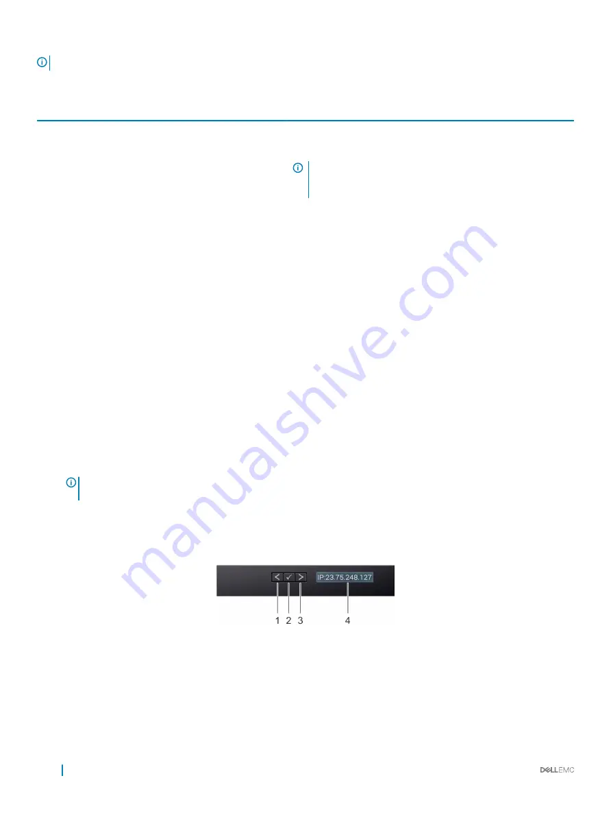
LCD panel
The LCD panel provides system information, status, and error messages to indicate if the system is functioning correctly or requires
attention. The LCD panel can be used to configure or view the system’s iDRAC IP address. For more information about error messages, see
the
Dell Event and Error Messages Reference Guide
at
Dell.com/openmanagemanuals
>
OpenManage software
.
The LCD panel is available only on the optional LCD bezel. The optional LCD bezel is hot pluggable.
The statuses and conditions of the LCD panel are outlined here:
•
The LCD backlight is white during normal operating conditions.
•
When the system needs attention, the LCD backlight turns amber, and displays an error code followed by descriptive text.
NOTE:
If the system is connected to a power source and an error is detected, the LCD turns amber regardless of whether
the system is turned on or off.
•
When the system turns off and there are no errors, LCD enters the standby mode after five minutes of inactivity. Press any button on
the LCD to turn it on.
•
If the LCD panel stops responding, remove the bezel and reinstall it. If the problem persists, see the Getting help section.
•
The LCD backlight remains off if LCD messaging is turned off using the iDRAC utility, the LCD panel, or other tools.
Figure 14. LCD panel features
20
PowerEdge R740xd system overview
Содержание PowerEdge R740xd
Страница 9: ...Figure 1 Supported configurations PowerEdge R740xd system overview 9 ...
Страница 151: ...Figure 103 Installing GPU 2 and 3 Installing and removing system components 151 ...
Страница 208: ...Related link Removing the system cover Installing the system cover 208 Jumpers and connectors ...


