background image

Steps

1. Peel the adhesive tape that covers the camera module.
2. Disconnect the display cable from the camera module.
3. Gently pry the camera shutter cap from the top edge of the camera shutter and remove it from the display back cover.
4. Gently pry the camera module from the display back cover.

Installing the camera

Prerequisites

If you are replacing a component, remove the existing component before performing the installation procedure.

About this task

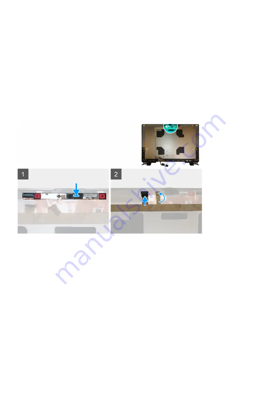
The figure indicates the camera and provides a visual representation of the installation procedure.

Steps

1. Place the camera module in its slot on the display back cover.
2. Place the camera shutter cap on the top edge of the camera shutter.
3. Connect the display cable to the camera module.
4. Adhere the adhesive tape to cover the camera module.

Next steps

1. Install the 

display panel

.

2. Install the 

display bezel

.

3. Install the 

speaker

.

4. Install the 

display assembly

.

5. Install the 

system board

.

6. Install the 

GPU card

.

7. Install the 

GPU power cable

.

8. Install the 

inner frame

.

9. Install the 

heat-sink assembly

.

10. Install the 

primary memory

.

11. Install the 

keyboard

.

12. Install the 

keyboard lattice

.

90

Adskillelse og samling

Содержание P93F

Страница 1: ...Precision 7550 Service Manual Regulatory Model P93F Regulatory Type P93F001 May 2020 Rev A00 ...

Страница 2: ... eller tab af data og oplyser dig om hvordan du kan undgå dette problem ADVARSEL ADVARSEL angiver risiko for tingskade legemsbeskadigelse eller død 2020 Dell Inc eller deres associerede selskaber Alle rettigheder forbeholdes Dell EMC og andre varemærker er varemærker tilhørende Dell Inc eller deres associerede selskaber Andre varemærker kan være varemærker for deres respektive ejere ...

Страница 3: ...Sådan fjernes SD kortet 17 Sådan monteres SD kortet 17 SSD dæksel 17 Removing SSD door 17 Installing SSD door 18 Sekundært M 2 solid state drev 19 Removing the secondary M 2 Solid state drive 19 Installing the secondary M 2 SSD module 20 Bunddæksel 21 Removing the base cover 21 Installing the base cover 24 Batteri 26 Forholdsregler for litium ion batteri 26 Removing the battery 26 Installing the b...

Страница 4: ...til tænd sluk knap med fingeraftrykslæser 48 Removing the power button assembly with fingerprint reader 48 Installing the power button assembly with fingerprint reader 49 Inderramme 49 Removing the inner frame 49 Installing the inner frame 50 Smartcard bur 51 Removing the smart card reader 51 Installing the smart card reader 52 Pegefelt knap 53 Removing the Touchpad buttons 53 Installing the Touch...

Страница 5: ...Skærmhængsler 86 Removing the display hinge 86 Installing the display hinge non touch 87 Kamera 89 Removing the camera non touch 89 Installing the camera 90 P sensorkort 91 Sådan fjernes P sensorkortet 91 Sådan monteres P sensorkortet 92 Skærmkabel 92 Removing the display cable 92 Installing the display cable 94 Display back cover 95 Replacing the display cable 95 4 Fejlfinding 97 Dell SupportAssi...

Страница 6: ...e dækket af garantien Læs og følg sikkerhedsinstruktionerne der blev leveret sammen med produktet FORSIGTIG For at undgå elektrostatisk afladning bør du jorde dig selv ved hjælp af en jordingsrem eller ved jævnligt at røre ved en umalet metaloverflade og samtidig røre ved et stik på computerens bagside FORSIGTIG Komponenter og kort skal behandles forsigtigt Rør ikke ved kortenes komponenter eller ...

Страница 7: ...l den samme elektriske styrke Dette gøres ved brug af en feltservicepakke til elektrostatisk afladning ESD Når en tilknytningsledning forbindes skal man sikre sig at den er forbundet til metal og aldrig til en malet eller umalet overflade Håndledsremmen bør være sikret og i fuld kontakt med din hud og du skal altid fjerne alle smykker såsom ure armbånd eller ringe før du tilkobler dig selv eller u...

Страница 8: ...um teste en gang om ugen En håndledsremtester er den bedste metode til at udføre denne test Hvis du ikke har din egen håndledsremtester skal du kontakte regionskontoret for at høre om de har en For at udføre testen skal du sætte håndledsremmens bindingsledning ind i testeren mens den er fastgjort til dit håndled og trykke på knappen for at teste Et grønt LED lys er tændt hvis testen går godt et rø...

Страница 9: ... 1 Tilslut telefon eller netværkskabler til computeren FORSIGTIG For at tilslutte et netværkskabel skal du først sætte det i netværksenheden og derefter sætte det i computeren 2 Tilslut computeren og alle tilsluttede enheder til deres stikkontakter 3 Tænd computeren 4 Du kan om nødvendigt få bekræftet at computeren fungerer korrekt ved at køre SupportAssist diagnosticering Sådan arbejder du med co...

Страница 10: ...perSpeed USB I mange år har USB 2 0 været veletableret som de facto standardgrænsefladen i pc verdenen med omkring 6 milliarder solgte enheder Nu er der et stigende behov for højere hastigheder samt større båndbredder som følge af den endnu hurtigere computerhardware USB 3 0 USB 3 1 Gen 1 har endelig svaret på kundernes krav med en teoretisk 10 gange højere hastighed end sin forgænger I bund og gr...

Страница 11: ...darden bane vejen for produkter der tidligere ikke var egnet til USB grænsefladen såsom eksterne RAID lagersystemer Herunder er oplistet nogle tilgængelige SuperSpeed USB 3 0 USB 3 1 Gen 1 produkter Eksterne USB 3 0 USB 3 2 Gen 1 harddiske Bærbare USB 3 2 Gen 1 harddiske Dockingstationer og adaptere til USB 3 2 Gen 1 drev USB 3 2 Gen 1 flashdrev og læsere USB 3 2 Gen 1 SSD Solid state drev USB 3 2...

Страница 12: ... 2 dvs dobbelt så hurtig som første generation af Thunderbolt stik USB Type C er ikke det samme som USB 3 2 USB Type C er blot en stikform og den underliggende teknologi kan sagtens være blot USB 2 eller USB 3 0 Faktisk anvender Nokias N1 Android tablet et USB Type C stik men indeni er det hele USB 2 0 ikke engang USB 3 0 Teknologierne er dog nært beslægtede Thunderbolt over USB Type C Thunderbolt...

Страница 13: ...ved eliminere behovet for et separat lydkabel 3D Definerer input output protokoller for de fleste 3D videoformater og baner således vejen for 3D gaming og 3D hjemmeteater Indholdstype Realtidssignalering af indholdstyper mellem skærm og kildeenheder der gør det muligt for et TV at optimere illustrationsindstillingerne efter indholdstype Ekstra farvepladser Understøtter de ekstra farvemodeller som ...

Страница 14: ...1 4 7680 x 4320 8K ved 60 Hz mDP Type C til DP Antal skærmsupport Op til 4 skærme NVIDIA Quadro T2000 Tabel 3 NVIDIA Quadro T2000 Funktion Værdier Grafikkort hukommelse 4 GB Kerner 1024 Hukommelsesbåndbredde 128 Gbps Hukommelsestype GDDR6 Hukommelses grænseflade 128 bit Urhastigheder 1575 1785 boost MHz GPU basisur 3504 MHz min ved P0 Skønnet maksimal kraft 60 W Skærmunderstøttelse eDP mDP HDMI Ty...

Страница 15: ...l DP Maks digital To DisplayPorts 1 4 7680 x 4320 8K ved 60 Hz mDP Type C til DP Antal skærmsupport Op til 4 skærme NVIDIA Quadro RTX4000 Table 5 NVIDIA Quadro RTX4000 Feature Values Graphics memory 8 GB Cores 2560 Memory bandwidth 448 Gbps Memory type GDDR6 Memory Interface 256 bit Clock Speeds 1110 1560 Boost MHz GPU base clock 14000 MHz Estimated Maximum Power 80 W Display Support eDP mDP HDMI ...

Страница 16: ...imum Power 80 W Display Support eDP mDP HDMI Type C Maximum Color Depth Up to 10 bit color Operating Systems Graphics Video API Support DirectX 12 0 OpenGL 4 6 DisplayPort 1 4 DirectX 12 1 Supported Resolutions and Max Refresh Rates Hz Max Digital Single DisplayPort 1 4 7680 x 4320 8k 30 Hz mDP Type C to DP Max Digital Dual DisplayPort 1 4 7680 x 4320 8k 60 Hz mDP Type C to DP Numbers of Display S...

Страница 17: ... den eksisterende komponent før installationsproceduren foretages Om denne opgave Figuren angiver placeringen af bunddækslet og giver en visuel fremstilling af installationsproceduren Billeder der skal uploades i næste gennemgangscyklus Trin Skub SD kortet ind i slottet på computeren indtil det klikker på plads Næste trin 1 Følg proceduren i Efter du har udført arbejde på computerens indvendige de...

Страница 18: ... the base cover Installing SSD door Prerequisites If you are replacing a component remove the existing component before performing the installation procedure About this task The figure indicates the location of the SSD door and provides a visual representation of the installation procedure 18 Adskillelse og samling ...

Страница 19: ...t M 2 solid state drev Removing the secondary M 2 Solid state drive Prerequisites NOTE For computers shipped with M 2 2280 or 2230 SSD installed in slot 4 1 Follow the procedure in before working inside your computer 2 Remove the SD card 3 Remove the SSD door About this task The figure indicates the location of the secondary M 2 SSD and provides a visual representation of the removal procedure Ads...

Страница 20: ...For M 2 2230 SSD a Remove the M 2 2230 SSD with its holder from the SSD carrier b Remove the M2x2 screw to secure the M 2 2230 SSD to its holder c Remove the SSD from the holder Installing the secondary M 2 SSD module Prerequisites NOTE For computers shipped with M 2 2280 or 2230 SSD installed in slot 4 If you are replacing a component remove the existing component before performing the installati...

Страница 21: ...thermal plate to the M 2 SSD 5 Replace the SSD module in its slot on the computer 6 Replace the M2x3 screw to secure the SSD module in place Next steps 1 Install the SSD door 2 Install the SD card 3 Follow the procedure in after working inside your computer Bunddæksel Removing the base cover Prerequisites 1 Follow the procedure in before working inside your computer 2 Remove the SD card About this...

Страница 22: ...22 Adskillelse og samling ...

Страница 23: ...pen the base cover starting from bottom edge of the cover NOTE For models shipped without SmartCard reader pry open the base cover from the smart card reader slot Use your fingers to pry open the base cover as the use of plastic scribe or any other sharp objects may damage the base cover Adskillelse og samling 23 ...

Страница 24: ...tor on the system board Installing the base cover Prerequisites If you are replacing a component remove the existing component before performing the installation procedure About this task The figure indicates the location of the base cover and provides a visual representation of the installation procedure 24 Adskillelse og samling ...

Страница 25: ...Adskillelse og samling 25 ...

Страница 26: ...n af batteriet under tryk Bøj ikke batteriet Brug ikke værktøj af nogen art til at lirke på batteriet Sørg for at alle skruer under serviceringen af dette produkt ikke forsvinder eller lægges det forkerte sted for at undgå at batteriet eller andre systemkomponenter får huller eller tager skade Hvis batteriet sidder fast i en enhed på grund af opsvulmning må du ikke forsøge at frigøre det da punkte...

Страница 27: ...n the battery 3 Remove the battery away from the computer Installing the battery Prerequisites If you are replacing a component remove the existing component before performing the installation procedure About this task The figure indicates the location of the battery and provides a visual representation of the installation procedure Adskillelse og samling 27 ...

Страница 28: ... in after working inside your computer Solid state drev Removing the primary M 2 Solid state drive Prerequisites NOTE For computers shipped with M 2 2280 or 2230 SSD installed in slot 3 and or slot 5 1 Follow the procedure in before working inside your computer 2 Remove the SD card 3 Remove the base cover About this task The figure indicates the location of the primary M 2 SSD and provides a visua...

Страница 29: ...hat secures the M 2 SSD to the computer b Remove the M 2 SSD 4 For M 2 2230 SSD a Remove the M2x3 screw that secures the SSD module b Remove the SSD module from the computer c Remove the M2x2 screw that secures the SSD to SSD holder d Remove the SSD from the holder 5 Repeat the above steps to remove the other SSD modules in the computer Adskillelse og samling 29 ...

Страница 30: ...move the existing component before performing the installation procedure About this task The figure indicates the location of the primary M 2 SSD and provides a visual representation of the installation procedure Steps 1 For M 2 2280 SSD a Place the M 2 SSD onto its slot on the computer b Replace the M2x3 screw to secure the M 2 SSD to the computer 30 Adskillelse og samling ...

Страница 31: ... computer Next steps 1 Install the base cover 2 Install the SD card 3 Follow the procedure in after working inside your computer Sekundært hukommelsesmodul Removing the secondary memory module Prerequisites 1 Follow the procedure in before working inside your computer 2 Remove the SD card 3 Remove the base cover About this task The figure indicates the location of the secondary memory module and p...

Страница 32: ... memory module firmly into the slot and press the memory module until it clicks into place NOTE If you do not hear the click remove the memory module and reinstall it Next steps 1 Install the base cover 2 Install the SD card 3 Follow the procedure in after working inside your computer SIM kort Removing the SIM card Prerequisites 1 Follow the procedure in before working inside your computer 2 Remov...

Страница 33: ... opening 2 Filp the right edge of the SIM card cover to open it 3 Remove the SIM card from the SIM card slot Installing the SIM card Prerequisites If you are replacing a component remove the existing component before performing the installation procedure About this task The figure indicates the location of the SIM card and provides a visual representation of the installation procedure Adskillelse ...

Страница 34: ...r 2 Install the SD card 3 Follow the procedure in after working inside your computer WLAN kort Removing the WLAN card Prerequisites 1 Follow the procedure in before working inside your computer 2 Remove the SD card 3 Remove the base cover About this task The figure indicates the location of the WLAN card and provides a visual representation of the removal procedure 34 Adskillelse og samling ...

Страница 35: ...remove the existing component before performing the installation procedure About this task The figure indicates the location of the WLAN card and provides a visual representation of the installation procedure Steps 1 Insert the WLAN card to the connector on the system board 2 Connect the antenna cables to the WLAN card 3 Align and place the WLAN card bracket above the WLAN card to secure the anten...

Страница 36: ...ures the WWAN card bracket to the system board 2 Lift the WWAN card bracket from the WWAN card 3 Disconnect the antenna cables from the connector on the WWAN card 4 Slide and remove the WWAN card from its slot on the system board Installing the WWAN card Prerequisites If you are replacing a component remove the existing component before performing the installation procedure About this task The fig...

Страница 37: ...ter Tastaturgitter Removing the keyboard lattice Prerequisites 1 Follow the procedure in before working inside your computer 2 Remove the SD card 3 Remove the base cover About this task The figure indicates the location of the keyboard lattice and provides a visual representation of the removal procedure Steps 1 Using a plastic scribe pry the top edge of the keyboard lattice starting from the rece...

Страница 38: ...e Steps 1 Align the keyboard lattice to its position on the keyboard 2 Press the edges on the keyboard lattice until it clicks into place Next steps 1 Install the base cover 2 Install the SD card 3 Follow the procedure in after working inside your computer Tastatur Removing the keyboard Prerequisites 1 Follow the procedure in before working inside your computer 2 Remove the SD card 3 Remove the ba...

Страница 39: ...ard to the palmrest 4 Pry the bottom edge of the keyboard and then work along the left and the right sides of the keyboard 5 Carefully unroute the keyboard backlight cable and the keyboard cable through the palmrest 6 Remove the keyboard from the system Installing the keyboard Prerequisites If you are replacing a component remove the existing component before performing the installation procedure ...

Страница 40: ...tem at 90 angle to access the keyboard and the keyboard backlight cables 5 Connect the keyboard backlight cable and the keyboard cable to the connectors on the system board NOTE Ensure that you fold the keyboard data cable in perfect alignment Next steps 1 Install the keyboard lattice 2 Install the battery 3 Install the base cover 4 Install the SD card 5 Follow the procedure in after working insid...

Страница 41: ... the SD card 3 Remove the base cover 4 Remove the battery 5 Remove the keyboard lattice 6 Remove the keyboard About this task The figure indicates the location of the primary memory module and provides a visual representation of the removal procedure Steps 1 Remove the M2x3 screw that secures the memory shield in place Adskillelse og samling 41 ...

Страница 42: ...move the existing component before performing the installation procedure About this task The figure indicates the location of the primary memory module and provides a visual representation of the installation procedure Steps 1 Align the notch on the memory module with the tab on the memory module slot 2 Slide the memory module firmly into the slot at an angle and press the memory module down until...

Страница 43: ...efore working inside your computer 2 Remove the SD card 3 Remove the base cover 4 Remove the battery About this task The figure indicates the location of the heat sink assembly and provides a visual representation of the removal procedure Steps 1 Peel the power adapter cable from the heat sink assembly 2 Disconnect the two fan cables from the connectors on the system board 3 Loosen the eight capti...

Страница 44: ...1 Align and insert the heat sink assembly into its slot on the computer 2 Tighten the eight captive screws to secure the heat sink assembly to the system board NOTE Tighten the captive screws in the order stamped onto the heat sink next to the screws 1 2 3 4 5 6 7 8 3 Connect the two fan cables to the connector on the system board 4 Adhere the power adapter cable on the heat sink assembly Next ste...

Страница 45: ...that secures power adapter cable bracket 2 Remove the power adapter cable bracket from the computer 3 Lift the power adapter port from its slot on the palmrest 4 Slide the power adapter cable towards the rear side of the computer to remove the cable from the computer Installing the power adapter port Prerequisites If you are replacing a component remove the existing component before performing the...

Страница 46: ...s 1 Install the heat sink assembly 2 Install the battery 3 Install the base cover 4 Install the SD card 5 Follow the procedure in after working inside your computer Kort til tænd sluk knap Removing the power button board Prerequisites 1 Follow the procedure in before working inside your computer 2 Remove the SD card 3 Remove the base cover 4 Remove the battery 5 Remove the heat sink assembly About...

Страница 47: ...d with the power button board cable from the computer 5 Disconnect the power button board cable from the power button board Installing the power button board Prerequisites If you are replacing a component remove the existing component before performing the installation procedure About this task The figure indicates the location of the power button board and provides a visual representation of the ...

Страница 48: ...2 Install the battery 3 Install the base cover 4 Install the SD card 5 Follow the procedure in after working inside your computer Kort til tænd sluk knap med fingeraftrykslæser Removing the power button assembly with fingerprint reader Prerequisites 1 Follow the procedure in before working inside your computer 2 Remove the SD card 3 Remove the base cover 4 Remove the battery 5 Remove the heat sink...

Страница 49: ...nd provides a visual representation of the installation procedure Steps 1 Connect the power button board cable to the power button board 2 Align and place the power button board with power button cable into its slot on the computer 3 Replace the M2x3 screw to secure the power button board 4 Adhere the power button board cable to the palmrest 5 Connect the power button board cable to the connector ...

Страница 50: ...nd the ten M2x2 5 screws that secure the inner frame to the computer chassis 3 Remove the inner frame from the computer Installing the inner frame Prerequisites If you are replacing a component remove the existing component before performing the installation procedure About this task The figure indicates the location of the inner frame and provides a visual representation of the installation proce...

Страница 51: ...d 2 Install the WWAN card 3 Install the primary M 2 SSD 4 Install the battery 5 Install the base cover 6 Install the SD card 7 Follow the procedure in after working inside your computer Smartcard bur Removing the smart card reader Prerequisites 1 Follow the procedure in before working inside your computer 2 Remove the SD card 3 Remove the base cover 4 Remove the battery 5 Remove the primary M 2 SS...

Страница 52: ...he smart card reader cable from the touchpad 4 Remove the two M2x2 5 screws that secure the smart card reader to the computer 5 Remove the smart card reader from the computer Installing the smart card reader Prerequisites If you are replacing a component remove the existing component before performing the installation procedure About this task The figure indicates the location of the smart card re...

Страница 53: ...he primary M 2 SSD 2 Install the inner frame 3 Install the battery 4 Install the base cover 5 Install the SD card 6 Follow the procedure in after working inside your computer Pegefelt knap Removing the Touchpad buttons Prerequisites 1 Follow the procedure in before working inside your computer 2 Remove the SD card 3 Remove the base cover 4 Remove the battery 5 Remove the primary M 2 SSD 6 Remove t...

Страница 54: ...emove the touchpad buttons from the palmrest Installing the Touchpad buttons Prerequisites If you are replacing a component remove the existing component before performing the installation procedure About this task The figure indicates the location of the touchpad buttons and provides a visual representation of the installation procedure 54 Adskillelse og samling ...

Страница 55: ...ocedure in after working inside your computer SD kortlæser Removing SD card reader Prerequisites 1 Follow the procedure in before working inside your computer 2 Remove the SD card 3 Remove the base cover 4 Remove the battery 5 Remove the primary M 2 SSD 6 Remove the WWAN card 7 Remove the WLAN card 8 Remove the inner frame About this task The figure indicates the location of the SD card reader and...

Страница 56: ...vides a visual representation of the installation procedure Steps 1 Align and place the SD care reader with its slot on the palmrest 2 Replace the M2x2 screw to secure the SD card reader to the palmrest 3 Connect the LED board cable to the SD card reader on the bottom side of the computer 4 Connect the SD card reader cable to the connector on the system board Next steps 1 Install the inner frame 2...

Страница 57: ...ton and provides a visual representation of the removal procedure Steps 1 Remove the two M2x3 screws that secure the power button in its slot on the computer 2 Remove the power button from the computer Installing the power button Prerequisites If you are replacing a component remove the existing component before performing the installation procedure About this task The figure indicates the locatio...

Страница 58: ...side your computer Tænd sluk knapmodul med fingeraftrykslæser Removing the power button assembly with fingerprint reader Prerequisites 1 Follow the procedure in before working inside your computer 2 Remove the SD card 3 Remove the base cover 4 Remove the battery 5 Remove the heat sink assembly 6 Remove the power button board assembly with fingerprint reader About this task The figure indicates the...

Страница 59: ...int reader from the computer Installing the power button assembly with fingerprint reader Prerequisites If you are replacing a component remove the existing component before performing the installation procedure About this task The figure indicates the location of the power button and provides a visual representation of the installation procedure Adskillelse og samling 59 ...

Страница 60: ...edure in after working inside your computer GPU strømkabel Removing the GPU power cable Prerequisites 1 Follow the procedure in before working inside your computer 2 Remove the SD card 3 Remove the base cover 4 Remove the battery 5 Remove the keyboard lattice 6 Remove the keyboard About this task The figure indicates the location of the GPU power cable and provides a visual representation of the r...

Страница 61: ...es the location of the GPU power cable and provides a visual representation of the installation procedure Steps 1 Adhere the GPU power cable into its slot on the computer 2 Disconnect the GPU power cable from the connector on the system board 3 Slide the GPU power cable connector into its slot to connect the GPU power cable to the GPU card 4 Lock the GPU power cable connector to secure the GPU car...

Страница 62: ...M card 9 Remove the secondary memory 10 Remove the WWAN card 11 Remove the WLAN card 12 Remove the keyboard lattice 13 Remove the keyboard 14 Remove the primary memory 15 Remove the heat sink assembly 16 Remove the inner frame About this task The figure indicates the location of the system board and provides a visual representation of the removal procedure Images to be uploaded in the next review ...

Страница 63: ...mera power adapter cable touchpad cable USH daughter board cable for models shipped with a USH daughter board and power button board cable from the system board 5 Remove the M2x3 screw that secures the Darwin cable bracket in place 6 Remove the Darwin cable bracket 7 Disconnect the Darwin cables from the connectors on the system board 8 Remove the six M2x3 screws that secure the three beam connect...

Страница 64: ...system board 14 Remove the three M2x5 screws that secure the system board to the computer 15 Pry the coin cell battery located under the system board from the palmrest while lifting the system board 16 Remove the system board from the computer Installing the system board Prerequisites If you are replacing a component remove the existing component before performing the installation procedure About ...

Страница 65: ...Adskillelse og samling 65 ...

Страница 66: ...ble connector 8 Replace the M2x3 screw to secure the Darwin cable bracket to the system board 9 Connect the beam connectors on the system board NOTE For UMA models replace the two M2x3 screws to secure the single beam connector in place on the bottom side of the system For discrete models shipped with a 128 MB vram GPU card replace the four M2x3 screws to secure the two beam connector in place on ...

Страница 67: ...D kortet 3 Fjern SSD dækslet 4 Fjern det sekundære M 2 SSD 5 Fjern bunddækslet 6 Fjern batteriet 7 Fjern det primære M 2 SSD 8 Fjern SIM kortet 9 Fjern den sekundære hukommelse 10 Fjern WWAN kortet 11 Fjern WLAN kort 12 Fjern tastaturgitteret 13 Fjern tastaturet 14 Fjern GPU strømkablet 15 Fjern den primære hukommelse 16 Fjern varmelegememodulet 17 Fjern inderrammen 18 Fjern systemkortet Om denne ...

Страница 68: ...onter tastaturet 7 Monter tastaturgitteret 8 Monter WLAN kortet 9 Monter WWAN kortet 10 Monter den sekundære hukommelse 11 Monter SIM kortet 12 Monter det primære M 2 SSD 13 Monter batteriet 14 Monter bunddækslet 15 Monter det sekundære M 2 SSD 16 Monter SSD dækslet 17 Monter SD kortet 18 Følg proceduren i Efter du har udført arbejde på computerens indvendige dele Højttaler Removing the speaker Pr...

Страница 69: ...next review cycle Steps 1 Peel the pieces of adhesive tape that secures the speaker cable to the palmrest 2 Pry the speaker module from its slot on the top edge of the palmrest 3 Remove the speaker module from the computer Installing the speaker Prerequisites If you are replacing a component remove the existing component before performing the installation procedure About this task The figure indic...

Страница 70: ...the inner frame 5 Install the heat sink assembly 6 Install the primary memory 7 Install the keyboard 8 Install the keyboard lattice 9 Install the WLAN card 10 Install the WWAN card 11 Install the secondary memory 12 Install the SIM card 13 Install the primary M 2 SSD 14 Install the battery 15 Install the base cover 16 Install the secondary M 2 SSD 17 Install the SSD door 18 Install the SD card 19 ...

Страница 71: ...WWAN card 11 Remove the WLAN card 12 Remove the keyboard lattice 13 Remove the keyboard 14 Remove the primary memory 15 Remove the heat sink assembly 16 Remove the inner frame 17 Remove the GPU power cable 18 Remove the GPU card 19 Remove the system board About this task The figure indicates the location of the speaker and provides a visual representation of the removal procedure Images to be uplo...

Страница 72: ...palmrest NOTE Ensure that the middle cap is secured in place by the two pegs on the palmrest 2 Replace the four M2x3 screws to secure the middle cap in place Next steps 1 Install the system board 2 Install the GPU card 3 Install the GPU power cable 4 Install the inner frame 5 Install the heat sink assembly 6 Install the primary memory 7 Install the keyboard 8 Install the keyboard lattice 9 Install...

Страница 73: ...d 3 Remove the SSD door 4 Remove the secondary M 2 SSD 5 Remove the base cover 6 Remove the battery 7 Remove the primary M 2 SSD 8 Remove the SIM card 9 Remove the secondary memory 10 Remove the WWAN card 11 Remove the WLAN card 12 Remove the keyboard lattice 13 Remove the keyboard 14 Remove the primary memory 15 Remove the heat sink assembly About this task The figure indicates the location of th...

Страница 74: ...74 Adskillelse og samling ...

Страница 75: ... M2 5x2 5 screws that secures the hinges to the palmrest 8 Remove the display assembly from the palmrest NOTE The touch display assembly for Precision 7550 is a Hinge Up Design HUD assembly and cannot be further disassembled once it is removed from the bottom chassis If any components in the touch display assembly are malfunctioning and need to be replaced replace the entire touch display assembly...

Страница 76: ...76 Adskillelse og samling ...

Страница 77: ...ay bracket to the palmrest 4 Connect the display cable to the connector on the system board 5 Replace the M2x5 screw to secure the Darwin bracket 6 Adhere the WWAN cables and Darwin cables to the palmrest 7 Connect the power button board cable to the power button board Next steps 1 Install the heat sink assembly 2 Install the primary memory 3 Install the keyboard 4 Install the keyboard lattice 5 I...

Страница 78: ...N card 12 Remove the keyboard lattice 13 Remove the keyboard 14 Remove the primary memory 15 Remove the power adapter port 16 Remove the power button board 17 Remove the smart card reader 18 Remove the touchpad buttons 19 Remove the SD card reader 20 Remove the power button or power button assembly with fingerprint reader 21 Remove the heat sink assembly 22 Remove the inner frame 23 Remove the GPU...

Страница 79: ... existing component before performing the installation procedure About this task The figure indicates the palmrest and before performing the pre installation parts procedures for any palmrest installation procedure Next steps 1 Install the display assembly Adskillelse og samling 79 ...

Страница 80: ...nstall the battery 24 Install the base cover 25 Install the secondary M 2 SSD 26 Install the SSD door 27 Install the SD card 28 Follow the procedure in after working inside your computer Skærmfacet Removing the display bezel non touch Prerequisites 1 Follow the procedure in before working inside your computer 2 Remove the SD card 3 Remove the SSD door 4 Remove the secondary M 2 SSD 5 Remove the ba...

Страница 81: ... around the sides and top edge of the display bezel NOTE While prying the display bezel make sure to pry along the outside edge of the display bezel using your hands using a screw driver or other sharp objects may damage the display cover 3 Remove the display bezel from the display assembly Installing the display bezel non touch Prerequisites If you are replacing a component remove the existing co...

Страница 82: ...tall the GPU card 6 Install the GPU power cable 7 Install the inner frame 8 Install the heat sink assembly 9 Install the primary memory 10 Install the keyboard 11 Install the keyboard lattice 12 Install the WLAN card 13 Install the WWAN card 14 Install the secondary memory 15 Install the SIM card 16 Install the primary M 2 SSD 17 Install the battery 18 Install the base cover 19 Install the seconda...

Страница 83: ...0 Remove the WWAN card 11 Remove the WLAN card 12 Remove the keyboard lattice 13 Remove the keyboard 14 Remove the primary memory 15 Remove the heat sink assembly 16 Remove the inner frame 17 Remove the GPU power cable 18 Remove the GPU card 19 Remove the system board 20 Remove the display assembly 21 Remove the speaker 22 Remove the middle cap 23 Remove the display assembly 24 Remove the display ...

Страница 84: ...el the adhesive tapes that secures the display cable 5 Peel the adhesive rubber strip covering the display cable 6 Unlock the display cable connector and then disconnect the display cable from the back of the display panel 7 Remove the display panel form the display assembly 8 Remove the display panel NOTE The support brackets attached to the display panel are defined as a single service assembly ...

Страница 85: ...s a visual representation of the installation procedure Steps 1 Connect the display cable to the connector on the back of the display panel and lock the display cable connector 2 Adhere the adhesive rubber strip to cover the display cable 3 Adhere the transparent tape and conductive tape above the rubber strip to cover the display cable 4 Align the display panel with the tabs on the display assemb...

Страница 86: ...y 20 Install the base cover 21 Install the secondary M 2 SSD 22 Install the SSD door 23 Install the SD card 24 Follow the procedure in after working inside your computer Skærmhængsler Removing the display hinge Prerequisites 1 Follow the procedure in before working inside your computer 2 Remove the SD card 3 Remove the SSD door 4 Remove the secondary M 2 SSD 5 Remove the base cover 6 Remove the ba...

Страница 87: ...e Steps 1 Remove the eight M2 5x2 5 screws that secures the display hinges to the display assembly 2 Remove the display hinges Installing the display hinge non touch Prerequisites If you are replacing a component remove the existing component before performing the installation procedure About this task The figure indicates the display hinge and provides a visual representation of the installation ...

Страница 88: ...7 Install the GPU power cable 8 Install the inner frame 9 Install the heat sink assembly 10 Install the primary memory 11 Install the keyboard 12 Install the keyboard lattice 13 Install the WLAN card 14 Install the WWAN card 15 Install the secondary memory 16 Install the SIM card 17 Install the primary M 2 SSD 18 Install the battery 19 Install the base cover 20 Install the secondary M 2 SSD 21 Ins...

Страница 89: ...ve the WLAN card 12 Remove the keyboard lattice 13 Remove the keyboard 14 Remove the primary memory 15 Remove the heat sink assembly 16 Remove the inner frame 17 Remove the GPU power cable 18 Remove the GPU card 19 Remove the system board 20 Remove the display assembly 21 Remove the speaker 22 Remove the display bezel 23 Remove the display panel About this task The figure indicates the location of...

Страница 90: ...ra and provides a visual representation of the installation procedure Steps 1 Place the camera module in its slot on the display back cover 2 Place the camera shutter cap on the top edge of the camera shutter 3 Connect the display cable to the camera module 4 Adhere the adhesive tape to cover the camera module Next steps 1 Install the display panel 2 Install the display bezel 3 Install the speaker...

Страница 91: ...mære M 2 SSD 8 Fjern SIM kortet 9 Fjern den sekundære hukommelse 10 Fjern WWAN kortet 11 Fjern WLAN kort 12 Fjern tastaturgitteret 13 Fjern tastaturet 14 Fjern den primære hukommelse 15 Fjern varmelegememodulet 16 Fjern inderrammen 17 Fjern GPU strømkablet 18 Fjern GPU kortet 19 Fjern systemkortet 20 Fjern skærmmodulet 21 Fjern højttaleren 22 Fjern skærmrammen 23 Fjern skærmpanelet Om denne opgave...

Страница 92: ...tet 7 Monter GPU strømkablet 8 Monter inderrammen 9 Monter varmelegememodulet 10 Monter den primære hukommelse 11 Monter tastaturet 12 Monter tastaturgitteret 13 Monter WLAN kortet 14 Monter WWAN kortet 15 Monter den sekundære hukommelse 16 Monter SIM kortet 17 Monter det primære M 2 SSD 18 Monter batteriet 19 Monter bunddækslet 20 Monter det sekundære M 2 SSD 21 Monter SSD dækslet 22 Monter SD ko...

Страница 93: ...embly 21 Remove the speaker 22 Remove the display bezel 23 Remove the display panel 24 Remove the P sensor board About this task The figure indicates the location of the display cable and provides a visual representation of the removal procedure Images to be uploaded in the next review cycle Steps 1 Peel the adhesive tape covering the camera module 2 Disconnect the display cable from the camera mo...

Страница 94: ...des a visual representation of the installation procedure Steps 1 Route and adhere the display cable on the display back cover 2 Connect the display cable to the connector on the camera module 3 Adhere the adhesive tape to cover the camera module Next steps 1 Install the P sensor board 2 Install the display panel 3 Install the display bezel 4 Install the speaker 5 Install the display assembly 6 In...

Страница 95: ...ard 3 Remove the SSD door 4 Remove the secondary M 2 SSD 5 Remove the base cover 6 Remove the battery 7 Remove the primary M 2 SSD 8 Remove the SIM card 9 Remove the secondary memory 10 Remove the WWAN card 11 Remove the WLAN card 12 Remove the keyboard lattice 13 Remove the keyboard 14 Remove the primary memory 15 Remove the heat sink assembly 16 Remove the inner frame 17 Remove the GPU power cab...

Страница 96: ...U card 11 Install the GPU power cable 12 Install the inner frame 13 Install the heat sink assembly 14 Install the primary memory 15 Install the keyboard 16 Install the keyboard lattice 17 Install the WLAN card 18 Install the WWAN card 19 Install the secondary memory 20 Install the SIM card 21 Install the primary M 2 SSD 22 Install the battery 23 Install the base cover 24 Install the secondary M 2 ...

Страница 97: ...tning BEMÆRK Nogle tests til specifikke enheder kræver brugerinteraktion Sørg altid for at du er tilstede ved computerterminalen når diagnostiktestene er udført Find yderligere oplysninger under Resolve Hardware Issues With Built in and Online Diagnostics SupportAssist ePSA ePSA or PSA Error Codes Kørsel af SupportAssist Pre Boot System Performance Check Trin 1 Tænd computeren 2 Når computeren sta...

Страница 98: ...is systemkortet fungerer korrekt Indbygget selvtest af strømskinne til skærmpanel L BIST Om denne opgave Næste trin L BIST test af LCD strømskinne er en forbedring af diagnosticeringen hvor kun én LED fejlkode vises og den aktiveres automatisk under POST L BIST isolerer om LCD et modtager strøm fra systemkortet L BIST kontrollerer om systemkortet leverer strøm til LCD et ved at udføre en test af L...

Страница 99: ... charge Amber Computer is running on battery and the battery has less than 5 percent charge Off Power adapter is connected and the battery is fully charged Computer is running on battery and the battery has more than 5 percent charge Computer is in sleep state hibernation or turned off The power and battery status light blinks amber along with beep codes indicating failures For example the power a...

Страница 100: ...OS version If problem persists replace the LCD module 2 8 LCD failure EC detection of power rail failure Replace the system board 3 1 CMOS battery failure Reset the CMOS battery connection If problem persists replace the RTC battery 3 2 PCI of Video card chip failure Replace the system board 3 3 BIOS Recovery Image not found Flash latest BIOS version If problem persists replace the system board 3 ...

Страница 101: ...rvice Providers har en kombineret modem router enhed Trin 1 Sluk for computeren 2 Sluk for modemmet 3 Sluk for den trådløse router 4 Vent i 30 sekunder 5 Tænd den trådløse router 6 Tænd for modemmet 7 Tænd computeren Fejlfinding 101 ...

Страница 102: ...baseret support og service Tilgængeligheden varierer for de enkelte lande og produkter og nogle tjenester findes muligvis ikke i dit område Sådan kontakter du Dell omkring salg teknisk support eller kundeservice Trin 1 Gå til Dell com support 2 Vælg supportkategori 3 Bekræft dit land eller område i rullemenuen Choose a Country Region Vælg land område fra listen nederst på siden 4 Vælg det relevant...

Отзывы: