background image

Wireless card

Removing the wireless card

Prerequisites

1. Follow the procedure in 

Before working inside your computer

.

2. Enter 

Service Mode

.

3. Remove the 

base cover

.

About this task

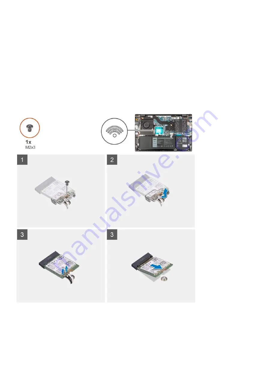
The following image(s) indicate the location of the wireless card and provides a visual representation of the removal procedure.

Steps

1. Remove the screw (M2x3) that secures the wireless-card bracket to the wireless card and system board.
2. Lift the wireless-card bracket off the wireless card.
3. Disconnect the antenna cables from the wireless card.
4. Slide and remove the wireless card from the M.2 card slot on the system board.

28

Removing and installing components

Содержание P143G

Страница 1: ...Vostro 14 5410 Service Manual Regulatory Model P143G Regulatory Type P143G001 April 2021 Rev A00 ...

Страница 2: ...ential damage to hardware or loss of data and tells you how to avoid the problem WARNING A WARNING indicates a potential for property damage personal injury or death 2021 Dell Inc or its subsidiaries All rights reserved Dell EMC and other trademarks are trademarks of Dell Inc or its subsidiaries Other trademarks may be trademarks of their respective owners ...

Страница 3: ...ttery 19 Memory module 20 Removing the memory 20 Installing the memory 21 Solid state drive 23 Removing the M 2 2230 solid state drive 23 Installing the M 2 2230 solid state drive 23 Removing the M 2 2280 solid state drive 24 Installing the M 2 2280 solid state drive 25 Installing the solid state drive mounting bracket 26 Wireless card 28 Removing the wireless card 28 Installing the wireless card ...

Страница 4: ...alm rest and keyboard assembly 57 Installing the palm rest and keyboard assembly 58 Chapter 3 Drivers and downloads 60 Chapter 4 System setup 61 BIOS overview 61 Entering BIOS setup program 61 Navigation keys 61 Boot Sequence 61 Advanced or Engineering configurations 62 SupportAssist system resolution 62 System setup options 62 Updating the BIOS in Windows 72 Updating BIOS on systems with BitLocke...

Страница 5: ...Flashing the BIOS 77 WiFi power cycle 78 Flea power release 78 Chapter 6 Getting help 79 Contacting Dell 79 Contents 5 ...

Страница 6: ...zed by Dell is not covered by your warranty See the safety instructions that is shipped with the product or at www dell com regulatory_compliance CAUTION Before touching anything inside your computer ground yourself by touching an unpainted metal surface such as the metal at the back of the computer While you work periodically touch an unpainted metal surface to dissipate static electricity which ...

Страница 7: ...memory errors etc The more difficult type of damage to recognize and troubleshoot is the intermittent also called latent or walking wounded failure Perform the following steps to prevent ESD damage Use a wired ESD wrist strap that is properly grounded The use of wireless anti static straps is no longer allowed they do not provide adequate protection Touching the chassis before handling parts does ...

Страница 8: ... over and taped shut and all the same foam packing material should be used in the original box that the new part arrived in ESD sensitive devices should be removed from packaging only at an ESD protected work surface and parts should never be placed on top of the ESD bag because only the inside of the bag is shielded Always place parts in your hand on the ESD mat in the system or inside an anti st...

Страница 9: ...functioning mode After working inside your computer About this task CAUTION Leaving stray or loose screws inside your computer may severely damage your computer Steps 1 Replace all screws and ensure that no stray screws remain inside your computer 2 Connect any external devices peripherals or cables you removed before working on your computer 3 Replace any media cards discs or any other parts that...

Страница 10: ...antity of screws and then place them in a screw storage box This is to ensure that the correct number of screws and correct screw type is restored when the component is replaced NOTE Some computers have magnetic surfaces Ensure that the screws are not left attached to such surface when replacing a component NOTE Screw color may vary with the configuration ordered Table 1 Screw list Component Screw...

Страница 11: ...antity Screw image Type C bracket M2x4 2 Power button with fingerprint reader M2x3 1 Network port bracket M2x5 2 I O board M2x3 1 Touchpad M1 6x2 M2x1 8 3 2 Power adapter M2 5x5 2 Display assembly M2 5x5 4 Removing and installing components 11 ...

Страница 12: ...1 Base cover 2 Heat sink 3 System board 4 Memory module 5 Battery 6 Speakers 7 Palm rest and keyboard assembly 8 Touchpad 9 Display assembly 10 Coin cell battery 11 I O board 12 M 2 2280 SSD card 12 Removing and installing components ...

Страница 13: ...mer Contact your Dell sales representative for purchase options Base cover Removing the base cover Prerequisites 1 Follow the procedure in Before working inside your computer 2 Enter Service Mode About this task NOTE Before removing the base cover ensure that there is no micro SD card installed in the micro SD card slot on your computer The following image s indicate the location of the base cover...

Страница 14: ... bottom left and continue to work on the sides to open the base cover 4 Lift the base cover off the palm rest and keyboard assembly Installing the base cover Prerequisites If you are replacing a component remove the existing component before performing the installation process About this task The following image s indicate the location of the base cover and provides a visual representation of the ...

Страница 15: ...Removing and installing components 15 ...

Страница 16: ...ry to high temperatures or disassemble battery packs and cells Do not apply pressure to the surface of the battery Do not bend the battery Do not use tools of any kind to pry on or against the battery Ensure any screws during the servicing of this product are not lost or misplaced to prevent accidental puncture or damage to the battery and other system components If the battery gets stuck inside y...

Страница 17: ...oard assembly 4 Lift the battery off the palm rest and keyboard assembly Installing the 3 cell battery Prerequisites If you are replacing a component remove the existing component before performing the installation process About this task The following image s indicate the location of the 3 cell battery and provides a visual representation of the installation procedure Removing and installing comp...

Страница 18: ...ape that secures the battery cable to the 3 cell battery Next steps 1 Install the base cover 2 Follow the procedure in After working inside your computer Removing the 4 cell battery Prerequisites 1 Follow the procedure in Before working inside your computer 2 Remove the base cover About this task The following image s indicate the location of the 4 cell battery and provides a visual representation...

Страница 19: ...nd keyboard assembly 4 Lift the battery off the palm rest and keyboard assembly Installing the 4 cell battery Prerequisites If you are replacing a component remove the existing component before performing the installation process About this task The following image s indicate the location of the 4 cell battery and provides a visual representation of the installation procedure Removing and installi...

Страница 20: ...ecures the battery cable to the 4 cell battery Next steps 1 Install the base cover 2 Follow the procedure in After working inside your computer Memory module Removing the memory Prerequisites 1 Follow the procedure in Before working inside your computer 2 Enter Service Mode 3 Remove the base cover About this task The following image s indicate the location of the memory and provides a visual repre...

Страница 21: ...m board NOTE Your computer may have up to two memory modules installed Repeat steps 1 to 3 if there is a second memory module installed Installing the memory Prerequisites If you are replacing a component remove the existing component before performing the installation process About this task The following image s indicate the location of the memory and provides a visual representation of the inst...

Страница 22: ...nto the memory module slot on the system board 4 Press down on the memory module till the securing clips click locking the memory module in place NOTE Repeat steps 1 to 4 for each memory module being installed into your computer Next steps 1 Install the base cover 2 Exit Service Mode 3 Follow the procedure in After working inside your computer 22 Removing and installing components ...

Страница 23: ...lot M 2 2230 solid state drive M 2 2280 solid state drive The following image s indicate the location of the M 2 2230 solid state drive and provides a visual representation of the removal procedure Steps 1 Remove the screw M2x3 that secures the M 2 2230 solid state drive to the system board 2 Slide and lift the M 2 2230 solid state drive off the system board 3 Slide and lift the M 2 2230 solid sta...

Страница 24: ...notch on the M 2 2230 solid state drive with the tab on the M 2 card slot on the system board 2 Slide the M 2 2230 solid state drive into the M 2 card slot on the system board 3 Replace the screw M2x3 that secures the M 2 2230 solid state drive to the system board Next steps 1 Install the base cover 2 Exit Service Mode 3 Follow the procedure in After working inside your computer Removing the M 2 2...

Страница 25: ...tate drive from the M 2 card slot on the system board Installing the M 2 2280 solid state drive Prerequisites If you are replacing a component remove the existing component before performing the installation process About this task NOTE This procedure applies if you are installing a M 2 2280 solid state drive NOTE The M 2 card installed on your computer will depend on the configuration ordered Sup...

Страница 26: ...ive to the palm rest and keyboard assembly Next steps 1 Install the base cover 2 Exit Service Mode 3 Follow the procedure in After working inside your computer Installing the solid state drive mounting bracket About this task The following image provides a visual representation of the procedure to install the solid state drive mounting bracket when replacing a M 2 2230 solid state drive with a M 2...

Страница 27: ...ting bracket and mounting bracket slot 3 Slide and remove the solid state drive mounting bracket from the mounting bracket slot on the palm rest and keyboard assembly 4 Rotate the solid state drive mounting bracket 5 Slide the solid state mounting bracket into the mounting bracket slot on the palm rest and keyboard assembly 6 Adhere the Mylar that covers the solid state drive mounting bracket and ...

Страница 28: ...on of the wireless card and provides a visual representation of the removal procedure Steps 1 Remove the screw M2x3 that secures the wireless card bracket to the wireless card and system board 2 Lift the wireless card bracket off the wireless card 3 Disconnect the antenna cables from the wireless card 4 Slide and remove the wireless card from the M 2 card slot on the system board 28 Removing and i...

Страница 29: ...mage s indicate the location of the wireless card and provides a visual representation of the installation procedure Steps 1 Connect the antenna cables to the wireless card Table 2 Antenna cable color scheme Connectors on the wireless card Antenna cable color Silkscreen marking Main White MAIN white triangle Auxiliary Black AUX black triangle Removing and installing components 29 ...

Страница 30: ...ase cover 2 Exit Service Mode 3 Follow the procedure in After working inside your computer Fan Removing the fan Prerequisites 1 Follow the procedure in Before working inside your computer 2 Enter Service Mode 3 Remove the base cover About this task The following image s indicate the location of the fan and provides a visual representation of the removal procedure Steps 1 Disconnect the fan cable f...

Страница 31: ...representation of the installation procedure Steps 1 Place the fan on the palm rest and keyboard assembly 2 Align the screw holes on the fan with the screw holes on the palm rest and keyboard assembly 3 Replace the two screws M2x3 that secure the fan to the palm rest and keyboard assembly 4 Connect the fan cable to the system board Next steps 1 Install the base cover 2 Exit Service Mode 3 Follow t...

Страница 32: ... removal procedure Steps 1 Disconnect the coin cell battery from the I O board 2 Peel and lift the coin cell battery from the palm rest and keyboard assembly Installing the coin cell battery Prerequisites If you are replacing a component remove the existing component before performing the installation process About this task The following image s indicate the location of the coin cell battery and ...

Страница 33: ...your computer 2 Enter Service Mode 3 Remove the base cover About this task CAUTION The heat sink may become hot during normal operation Allow sufficient time for the heat sink to cool before you touch it NOTE For maximum cooling of the processor do not touch the heat transfer areas on the heat sink The oils in your skin can reduce the heat transfer capability of the thermal grease The following im...

Страница 34: ...at sink Prerequisites If you are replacing a component remove the existing component before performing the installation process About this task NOTE If either the system board or the heat sink is replaced use the thermal grease provided in the kit to ensure that thermal conductivity is achieved The following image s indicate the location of the heat sink and provides a visual representation of the...

Страница 35: ... to the system board NOTE The number of screws varies depending on the configuration ordered Next steps 1 Install the base cover 2 Exit Service Mode 3 Follow the procedure in After working inside your computer Network port bracket Removing the network port bracket Prerequisites 1 Follow the procedure in Before working inside your computer 2 Enter Service Mode 3 Remove the base cover Removing and i...

Страница 36: ...0 degrees 3 Remove the two screws M2x5 that secure the network port bracket to the I O board 4 Lift the network port bracket off the I O board Installing the network port bracket Prerequisites If you are replacing a component remove the existing component before performing the installation process About this task The following image s indicate the location of the network port bracket and provides ...

Страница 37: ...screws M2 5x5 that secure the left display hinge to the palm rest and keyboard assembly Next steps 1 Install the base cover 2 Exit Service Mode 3 Follow the procedure in After working inside your computer I O board Removing the I O board Prerequisites 1 Follow the procedure in Before working inside your computer 2 Enter Service Mode 3 Remove the base cover 4 Remove the network port bracket About t...

Страница 38: ...eader 3 Remove the screw M2x3 that secures the I O board to the palm rest and keyboard assembly 4 Disconnect the coin cell battery cable from the I O board 5 Lift the I O board off the palm rest and keyboard assembly Installing the I O board Prerequisites If you are replacing a component remove the existing component before performing the installation process About this task The following image s ...

Страница 39: ...he power button with fingerprint reader cable to the connector on the I O board and close the latch NOTE This step is only applicable for computers shipped with the optional fingerprint reader 7 Connect the coin cell battery cable to the I O board Next steps 1 Install the network port bracket 2 Install the base cover 3 Exit Service Mode 4 Follow the procedure in After working inside your computer ...

Страница 40: ...nect the touchpad cable from the system board 4 Lift the latch and disconnect the keyboard cable from the system board 5 Lift the latch and disconnect the keyboard backlight cable from the system board 6 Disconnect the speaker cable from the system board 7 Peel off the tape that secures the speaker cable to the palm rest and keyboard assembly 8 Remove the speaker cables from the routing guides on ...

Страница 41: ...s on the palm rest and keyboard assembly NOTE Ensure that the alignment posts are threaded through the rubber grommets on the speaker 2 Route the speaker cable through the routing guides on the palm rest and keyboard assembly 3 Connect the speaker cable to the connector on the system board 4 Adhere the tape that secures the speaker cable to the palm rest and keyboard assembly 5 Connect the touchpa...

Страница 42: ... the 3 cell battery or the 4 cell battery whichever applicable About this task The following image s indicate the location of the touchpad and provides a visual representation of the removal procedure Steps 1 Open the latch and disconnect the touchpad cable from the touchpad 2 Remove the three screws M1 6x2 that secure the touchpad bracket to the palm rest and keyboard assembly 3 Lift the touchpad...

Страница 43: ...image below shows the proper touchpad alignment for your computer 3 Close the display and place the computer in the position shown 4 Replace the two screws M2x1 8 that secure the touchpad to the palm rest and keyboard assembly 5 Place the touchpad bracket on the touchpad 6 Align the screw holes on the touchpad bracket to the screw holes on the palm rest and keyboard assembly 7 Replace the three sc...

Страница 44: ... computer Display assembly Removing the display assembly Prerequisites 1 Follow the procedure in Before working inside your computer 2 Enter Service Mode 3 Remove the base cover About this task The following image s indicate the location of the display assembly and provides a visual representation of the removal procedure 44 Removing and installing components ...

Страница 45: ...Removing and installing components 45 ...

Страница 46: ... I O board 6 Pry open the left display hinge at an angle of 90 degrees 7 Gently lift the palm rest and keyboard assembly off the display assembly CAUTION To avoid damaging the display do not slide the palm rest and keyboard assembly over the display assembly Installing the display assembly Prerequisites If you are replacing a component remove the existing component before performing the installati...

Страница 47: ...e screw holes on the I O board 4 Replace the two screws M2 5x5 that secure the left display hinge to the palm rest and keyboard assembly 5 Close the right display hinge and align the screw holes on the right display hinge with the screw holes on the system board 6 Replace the two screws M2 5x5 that secure the right display hinge to the palm rest and keyboard assembly 7 Connect the display cable to...

Страница 48: ...er Service Mode 3 Remove the base cover 4 Remove the I O board About this task The following image s indicate the location of the power button with optional fingerprint reader and provides a visual representation of the removal procedure Steps 1 Remove the screw M2x3 that secures the power button with optional fingerprint reader off the palm rest and keyboard assembly 2 Lift the power button with ...

Страница 49: ...es a visual representation of the installation procedure Steps 1 Using the alignment posts place the power button with optional fingerprint reader into its slot on the palm rest and keyboard assembly 2 Replace the screw M2x3 that secures the power button with optional fingerprint reader to the palm rest and keyboard assembly Next steps 1 Install the I O board 2 Install the base cover 3 Exit Servic...

Страница 50: ...0 degrees 3 Peel the tape that covers the power adapter port connector on the system board 4 Disconnect the power adapter port from the system board 5 Remove the power adapter port cable from the routing guides on the palm rest and keyboard assembly 6 Remove the power adapter port from the palm rest and keyboard assembly Installing the power adapter port Prerequisites If you are replacing a compon...

Страница 51: ...he two screws M2 5x5 that secures the right display hinge to the system board Next steps 1 Install the base cover 2 Exit Service Mode 3 Follow the procedure in After working inside your computer System board Removing the system board Prerequisites 1 Follow the procedure in Before working inside your computer 2 Remove the base cover 3 Remove the 3 cell battery or the 4 cell battery whichever applic...

Страница 52: ...cklight cable 4 keyboard cable 5 touchpad cable 6 speaker cable 7 I O board cable 8 fan cable The following image s indicate the location of the system board and provides a visual representation of the removal procedure 52 Removing and installing components ...

Страница 53: ...t display hinge at an angle of 90 degrees 3 Peel the tape that covers the power adapter port cable connector on the system board 4 Disconnect the power adapter port cable from the system board 5 Peel the tape that secures the display cable connector latch to the system board Removing and installing components 53 ...

Страница 54: ...omputers installed with a backlit keyboard 13 Remove the two screws M2x4 that secure the Type C port bracket to the system board 14 Lift the Type C port bracket off the system board 15 Remove the two screws M2x2 that secure the system board to the palm rest and keyboard assembly 16 Lift the system board from the palm rest and keyboard assembly Installing the system board Prerequisites If you are r...

Страница 55: ...The following image s indicate the location of the system board and provides a visual representation of the installation procedure Removing and installing components 55 ...

Страница 56: ...ype C port bracket to the system board 6 Connect the keyboard backlight cable to the connector on the system board and close the latch NOTE This step is only applicable if you are installing a backlit keyboard on your computer 7 Connect the keyboard cable to the connector on the system board and close the latch 8 Connect the touchpad cable to the connector on the system board and close the latch 9...

Страница 57: ...applicable 7 Install the base cover 8 Follow the procedure in After working inside your computer Palm rest and keyboard assembly Removing the palm rest and keyboard assembly Prerequisites 1 Follow the procedure in Before working inside your computer 2 Remove the base cover 3 Remove the 3 cell battery or the 4 cell battery whichever applicable 4 Remove the coin cell battery 5 Remove the M 2 2230 so...

Страница 58: ...d assembly Prerequisites If you are replacing a component remove the existing component before performing the installation process About this task The following image s indicate the location of the palm rest and keyboard assembly and provides a visual representation of the installation procedure 58 Removing and installing components ...

Страница 59: ...y assembly 4 Install the fan 5 Install the touchpad 6 Install the speakers 7 Install the I O board 8 Install the power adapter port 9 Install the wireless card 10 Install the M 2 2280 solid state drive 11 Install the M 2 2230 solid state drive 12 Install the coin cell battery 13 Install the 3 cell battery or the 4 cell battery whichever applicable 14 Install the base cover 15 Follow the procedure ...

Страница 60: ...rivers and downloads When troubleshooting downloading or installing drivers it is recommended that you read the Dell Knowledge Based article Drivers and Downloads FAQ SLN128938 3 60 Drivers and downloads ...

Страница 61: ... setup program About this task Turn on or restart your computer and press F2 immediately Navigation keys NOTE For most of the System Setup options changes that you make are recorded but do not take effect until you restart the system Keys Navigation Up arrow Moves to the previous field Down arrow Moves to the next field Enter Selects a value in the selected field if applicable or follow the link i...

Страница 62: ...ion Table 4 SupportAssit System Resolution Option Description Auto OS Recovery Threshold The Auto OS Recovery Threshold setup option controls the automatic boot flow for Support Assist System Resolution Console and Dell OS Recovery tool Choose one of the following options OFF 1 2 Default 3 SupportAssist OS Recovery Allows you to recover the SupportAssist OS Recovery Disabled by default System setu...

Страница 63: ...Processor L3 Cache Displays the processor L3 Cache size Current Clock Speed Displays the current processor clock speed Minimum Clock Speed Displays the minimum processor clock speed Microcode Version Displays the microcode version Intel Hyper Threading Capable Displays whether the processor is Hyper Threading HT capable 64 Bit Technology Displays whether 64 bit technology is used Memory Informatio...

Страница 64: ...able Custom Mode Enables or disables the PK KEK db and dbx security key databases to be manipulated Default OFF Custom Mode Key Management Default OFF Advanced Boot Options Enable UEFI Network Stack Enables or disables UEFI Network Stack Default PK Table 7 System setup options Integrated Devices menu System Configuration Date Time Date Sets the computer date in MM DD YYYY format Changes to the dat...

Страница 65: ...rives Miscellaneous Devices Enables or disables various onboard devices Enable Camera Enables or disables the camera Default ON Keyboard Illumination Configures the operating mode of the keyboard illumination feature Default Disabled The keyboard illumination will always be off Keyboard Backlight Timeout on AC Configures the timeout value for the keyboard when an AC adapter is connected to the com...

Страница 66: ...0 System setup options Connection menu Connection Network Controller Configuration Integrated NIC Allows pre OS and early OS networking features to use any enabled NICs Enabled with PXE Default Wireless Device Enable Enable or disable internal WLAN Bluetooth devices WLAN Default ON Bluetooth Default ON Enable UEFI Network Stack Allows pre OS and early OS networking features to use any enabled NICs...

Страница 67: ...NOTE If enabled the computer will not go to sleep Intel Rapid Start will be disabled automatically and the operating system power option will be blank if it was set to Sleep Lid Switch Enable Lid Switch Enables or disables lid switch Default ON Power On Lid Open Enables the computer to power up from the off state whenever the lid is opened Default ON Intel Speed Shift Technology Enables or disable...

Страница 68: ...on is enabled SMM Security Mitigation Enable or disable SMM Security Mitigation By default the option is enabled Data Wipe on Next Boot Start Data Wipe Enable or disable the data wipe on next boot By default the option is enabled Absolute Enable or disable or permanently disable the BIOS module interface of the optional Absolute Persistence Module service from Absolute software By default the opti...

Страница 69: ... to the Physical Security ID PSID revert of NVMe hard drives from the Dell Security Manager prompt By default the option is disabled Table 14 System setup options Update Recovery menu Update Recovery UEFI Capsule Firmware Updates Enable or disable BIOS updates through UEFI capsule update packages By default the option is enabled BIOS Recovery from Hard Drive Enables the user to recover from certai...

Страница 70: ...hen the computer boots By default the option is enabled Fn Lock Options By default the Fn lock option is enabled Lock Mode Lock Mode Standard Traditional F1 F12 functions Lock Mode Secondary Enables secondary functions on the Fn keys Table 17 System setup options Pre boot Behavior menu Pre boot Behavior Adapter Warnings Enable Adapter Warnings Enable or disable the warning messages during boot whe...

Страница 71: ...ltage and core frequency decreasing average power consumption and heat production By default the option is enabled C States Control Enable C State Control Enable or disable additional processor sleep states By default the option is enabled Intel Turbo Boost Technology Enable Intel Turbo Boost Technology Enable or disable Intel TurboBoost mode of the processor By default the option is enabled Intel...

Страница 72: ...ens 7 Click Find it myself 8 Click BIOS to view the BIOS versions 9 Identify the latest BIOS file and click Download 10 Select your preferred download method in the Please select your download method below window click Download File The File Download window appears 11 Click Save to save the file on your computer 12 Click Run to install the updated BIOS settings on your computer Follow the instruct...

Страница 73: ... a basic level of security for the data on your computer CAUTION Anyone can access the data stored on your computer if it is not locked and left unattended NOTE System and setup password feature is disabled Assigning a system setup password Prerequisites You can assign a new System or Admin Password only when the status is in Not Set About this task To enter the system setup press F2 immediately a...

Страница 74: ...ct System Security and press Enter The System Security screen is displayed 2 In the System Security screen verify that Password Status is Unlocked 3 Select System Password alter or delete the existing system password and press Enter or Tab 4 Select Setup Password alter or delete the existing setup password and press Enter or Tab NOTE If you change the System and or Setup password re enter the new ...

Страница 75: ...e performed For more information see Resolve Hardware Issues With Built in and Online Diagnostics SupportAssist ePSA ePSA or PSA Error Codes Running the SupportAssist Pre Boot System Performance Check Steps 1 Turn on your computer 2 As the computer boots press the F12 key as the Dell logo appears 3 On the boot menu screen select the Diagnostics option 4 Click the arrow at the bottom left corner Di...

Страница 76: ...iagnostics tools If problem persists replace the system board 2 2 System Board failure included BIOS corruption or ROM error Flash latest BIOS version If problem persists replace the system board 2 3 No Memory RAM detected Confirm that the memory module is installed properly If problem persists replace the memory module 2 4 Memory RAM failure Reset and swap memory modules amongst the slots If prob...

Страница 77: ...ot and fix your computer when it fails to boot into their primary operating system due to software or hardware failures For more information about the Dell SupportAssist OS Recovery see Dell SupportAssist OS Recovery User s Guide at www dell com support Flashing BIOS USB key Steps 1 Follow the procedure from step 1 to step 7 in Flashing the BIOS to download the latest BIOS setup program file 2 Cre...

Страница 78: ...formed The following procedure provides the instructions on how to conduct a WiFi power cycle NOTE Some ISPs Internet Service Providers provide a modem router combo device Steps 1 Turn off your computer 2 Turn off the modem 3 Turn off the wireless router 4 Wait for 30 seconds 5 Turn on the wireless router 6 Turn on the modem 7 Turn on your computer Flea power release About this task Flea power is ...

Страница 79: ...ne based support and service options Availability varies by country and product and some services may not be available in your area To contact Dell for sales technical support or customer service issues Steps 1 Go to Dell com support 2 Select your support category 3 Verify your country or region in the Choose a Country Region drop down list at the bottom of the page 4 Select the appropriate servic...

Отзывы: