6. Connect the WLAN-antenna cables to the respective connectors on the WLAN-antenna module.
7. Place the WLAN-antenna module bracket on the system board.
8. Align the screw holes on the WLAN-antenna module bracket with the screw holes on the system board.
9. Replace the screw (M2x2) to secure the WLAN-antenna module bracket to the system board.
10. Connect the touch-screen cable (for computers shipped with a touch screen), display cable, IR-camera cable (for computers
shipped with an IR camera), and sensor daughter-board cable (for computers shipped with a sensor board) to the system
board.
11. Place the display-cable bracket on the system board.
12. Align the screw holes on the display-cable bracket with the screw holes on the system board.
13. Replace the two screws (M2x2) to secure the display-cable bracket to the system board.
Next steps
1. Install the
.
2. Install the
.
After working inside your computer
.
Coin-cell battery
Removing the coin-cell battery
Prerequisites
Before working inside your computer
.
2. Remove the
.
3. Remove the
or the
, whichever applicable.
About this task
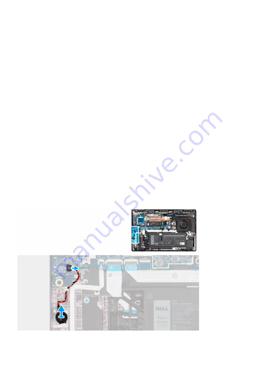
The following image indicates the location of the coin-cell battery and provides a visual representation of the removal procedure.
Steps
1. Disconnect the coin-cell battery cable from the connector on the system board.
40
Removing and installing components
Содержание P110F
Страница 1: ...Latitude 7530 Service Manual Regulatory Model P110F Regulatory Type P110F002 April 2022 Rev A00 ...
Страница 18: ...18 Removing and installing components ...
Страница 36: ...36 Removing and installing components ...
Страница 46: ...46 Removing and installing components ...
Страница 61: ...Removing and installing components 61 ...
Страница 70: ...70 Removing and installing components ...
Страница 82: ...82 Removing and installing components ...
Страница 104: ...To clear the alert set the Clear Intrusion Warning to ON in the Security menu of the BIOS setup 104 BIOS setup ...


