background image

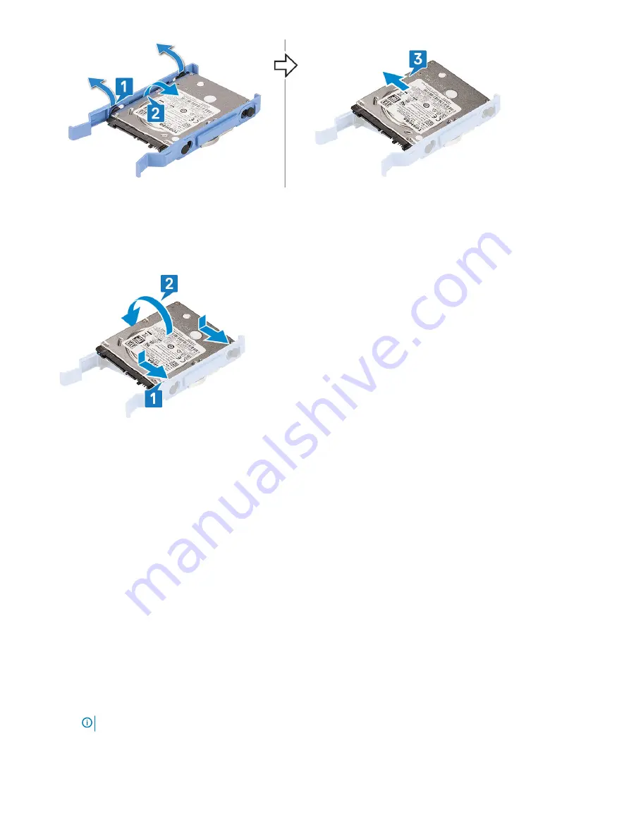
Installing the 3.5–inch hard drive into the hard drive bracket

Align the hard drive to the side of the hard drive bracket, and pull the other end tabs to insert the pins on the bracket into the hard 
drive [1].

Insert the hard drive into the hard drive bracket and press until it clicks into place [2].

Install the:

a

3.5-inch hard drive assembly

b

front bezel

c

side cover

Follow the procedure in 

After working inside your computer

.

2.5-inch hard drive assembly 

Removing the 2.5–inch drive assembly

Follow the procedure in 

Before working inside your computer

.

Remove the:

a

side cover

b

front bezel

Open the 

front panel door

.

To remove the drive assembly:

a Disconnect the drive assembly cables from the connectors on the drive [1] .
b Press the blue tabs on both sides [2] and pull the drive assembly out of the computer [3].

NOTE: 

Gently press the blue tabs to avoid damage to the plastic tabs.

22

Disassembly and reassembly

Содержание OpriPlex XE3

Страница 1: ...OptiPlex XE3 Tower Service Manual Regulatory Model D18M Regulatory Type D18M005 ...

Страница 2: ...amage to hardware or loss of data and tells you how to avoid the problem WARNING A WARNING indicates a potential for property damage personal injury or death 2018 Dell Inc or its subsidiaries All rights reserved Dell EMC and other trademarks are trademarks of Dell Inc or its subsidiaries Other trademarks may be trademarks of their respective owners 2018 05 Rev A00 ...

Страница 3: ...ges of Displayport over USB Type C 12 HDMI 2 0 12 HDMI 2 0 Features 12 Advantages of HDMI 13 3 Disassembly and reassembly 14 Side cover 14 Removing side cover 14 Installing side cover 14 Front Bezel 15 Removing front bezel 15 Installing front bezel 16 Front panel door 17 Opening the front panel door 17 Closing front panel door 17 3 5 inch hard drive 18 Removing 3 5 inch hard drive assembly 18 Inst...

Страница 4: ...unit or PSU 39 Installing power supply unit or PSU 40 Intrusion switch 42 Removing intrusion switch 42 Installing intrusion switch 43 Speaker 44 Removing speaker 44 Installing speaker 45 Power button 46 Removing power button 46 Installing power button 48 Heat sink fan 50 Removing heat sink fan 50 Installing heat sink fan 51 Coin cell battery 52 Removing coin cell battery 52 Installing coin cell ba...

Страница 5: ...4 Troubleshooting 67 Enhanced Pre Boot System Assessment ePSA diagnostics 67 Running the ePSA Diagnostics 67 Diagnostics 67 Battery status lights 69 5 Getting help 70 Contacting Dell 70 Contents 5 ...

Страница 6: ... same time as touching a connector on the back of the computer CAUTION Handle components and cards with care Do not touch the components or contacts on a card Hold a card by its edges or by its metal mounting bracket Hold a component such as a processor by its edges not by its pins CAUTION When you disconnect a cable pull on its connector or on its pull tab not on the cable itself Some cables have...

Страница 7: ...eriodically touching an unpainted metal surface at the same time as touching a connector on the back of the computer After working inside your computer After you complete any replacement procedure ensure that you connect any external devices cards and cables before turning on your computer 1 Connect any telephone or network cables to your computer CAUTION To connect a network cable first plug the ...

Страница 8: ... which requires 1 5 volts of electrical power to operate DDR4 also supports a new deep power down mode that allows the host device to go into standby without needing to refresh its memory Deep power down mode is expected to reduce standby power consumption by 40 to 50 percent DDR4 Details There are subtle differences between DDR3 and DDR4 memory modules as listed below Key notch difference The key...

Страница 9: ...ntroduced in 1996 It dramatically simplified the connection between host computers and peripheral devices like mice keyboards external drivers and printers Let s take a quick look on the USB evolution referencing to the table below Table 1 USB evolution Type Data Transfer Rate Category Introduction Year USB 3 0 USB 3 1 Gen 1 5 Gbps Super Speed 2010 USB 2 0 480 Mbps High Speed 2000 USB 3 1 Gen 2 10...

Страница 10: ...es the much higher performance by the technical changes below An additional physical bus that is added in parallel with the existing USB 2 0 bus refer to the picture below USB 2 0 previously had four wires power ground and a pair for differential data USB 3 0 USB 3 1 Gen 1 adds four more for two pairs of differential signals receive and transmit for a combined total of eight connections in the con...

Страница 11: ...f remains the same rectangular shape with the four USB 2 0 contacts in the exact same location as before Five new connections to carry receive and transmitted data independently are present on USB 3 0 USB 3 1 Gen 1 cables and only come into contact when connected to a proper SuperSpeed USB connection Windows 8 10 will be bringing native support for USB 3 1 Gen 1 controllers This is in contrast to ...

Страница 12: ...nologies are closely related Advantages of Displayport over USB Type C Full DisplayPort audio video A V performance up to 4K at 60Hz Reversible plug orientation and cable direction Backwards compatibility to VGA DVI with adaptors SuperSpeed USB USB 3 1 data Supports HDMI 2 0a and is backwards compatible with previous versions HDMI 2 0 This topic explains the HDMI 2 0 and its features along with th...

Страница 13: ... the highest crispest image quality Low cost HDMI provides the quality and functionality of a digital interface while also supporting uncompressed video formats in a simple cost effective manner Audio HDMI supports multiple audio formats from standard stereo to multichannel surround sound HDMI combines video and multichannel audio into a single cable eliminating the cost complexity and confusion o...

Страница 14: ...se the side cover from the computer 1 b Slide the side cover toward the back of the computer 2 c Lift the side cover to remove it from the computer Installing side cover 1 Place the side cover on the computer and slide the side cover forward 1 2 Slide the side cover until the click sound and the blue tab secures the side cover to the computer 2 3 14 Disassembly and reassembly ...

Страница 15: ...ow the procedure in Before working inside your computer 2 Remove the side cover 3 To remove the front bezel a Lift the tabs to release the front bezel from the chassis 1 b Push the front bezel away from the chassis 2 c Pull the front bezel to release it from the chassis 3 Disassembly and reassembly 15 ...

Страница 16: ...talling front bezel 1 Position the front bezel to align the tab holders on the chassis 2 Slide and press the front bezel until the tabs click in place 3 Install the side cover 16 Disassembly and reassembly ...

Страница 17: ...the a side cover b front bezel CAUTION The front panel door opens only to a limited extent See the printed image on the front panel door for the maximum permissible level 3 Pull the front panel door to open it Closing front panel door 1 Push the front panel door on the computer and press the side cover forward until the panel door clicks into place Disassembly and reassembly 17 ...

Страница 18: ...assembly 1 Follow the procedure in Before working inside your computer 2 Remove the a side cover b front bezel 3 To remove the hard drive assembly a Disconnect the hard drive assembly cables from the connectors on the hard drive NOTE Ensure to remove the SATA blue cable first to ease in removing the hard drive data cable 18 Disassembly and reassembly ...

Страница 19: ...b Pull the metal bracket that shields the hard drive assembly 1 c Press the blue tab 2 and pull the hard drive assembly out of the computer 3 Disassembly and reassembly 19 ...

Страница 20: ...hard drive assembly into the slot on the computer until it clicks into place 1 2 Close the metal bracket that shields the hard drive assembly 2 3 Connect the SATA cable and the power cable to the connectors on the hard drive 20 Disassembly and reassembly ...

Страница 21: ...puter 2 Remove the a side cover b front bezel c 3 5 inch hard drive assembly 3 To remove the hard drive bracket a Pull one side of the hard drive bracket to disengage the pins on the bracket from the slots on the hard drive 1 NOTE Do not pull plastic tab by more than 25 to avoid damage to the tabs b Pull the hard drive out of the hard drive bracket 2 c Lift the hard drive out of the hard drive bra...

Страница 22: ...c side cover 4 Follow the procedure in After working inside your computer 2 5 inch hard drive assembly Removing the 2 5 inch drive assembly 1 Follow the procedure in Before working inside your computer 2 Remove the a side cover b front bezel 3 Open the front panel door 4 To remove the drive assembly a Disconnect the drive assembly cables from the connectors on the drive 1 b Press the blue tabs on ...

Страница 23: ...h drive assembly 1 Insert the drive assembly into the slot on the computer and press until it clicks into place 1 2 2 Connect the SATA cable and the power cable to the connectors on the drive 3 Disassembly and reassembly 23 ...

Страница 24: ...5 inch drive from the drive bracket 1 Follow the procedure in Before Working Inside Your Computer 2 Remove the a side cover b front bezel c 2 5 inch drive assembly 3 To remove the drive a Pull one side of the drive bracket to disengage the pins on the bracket from the slots on the drive 1 b Lift the drive out of the drive bracket 2 24 Disassembly and reassembly ...

Страница 25: ...ive until it clicks into place 3 Install the a 2 5 inch drive assembly b front bezel c cover 4 Follow the procedure in After working inside your computer Optical drive Removing optical drive 1 Follow the procedure in Before working inside your computer 2 Remove the a side cover b front bezel 3 Open the front panel door 4 To remove the optical drive assembly a Disconnect the data cable and power ca...

Страница 26: ... from the tabs under the drive cage to allow you to disconnect the cables from the connectors b Close the front panel door 2 c Press the blue release tab 1 and slide the optical drive out of the computer 2 26 Disassembly and reassembly ...

Страница 27: ...Installing optical drive 1 Insert the optical drive into the optical drive bay until the blue release tab clicks into place Disassembly and reassembly 27 ...

Страница 28: ...2 Open the front panel door 2 3 Route the data cable and power cable under the drive cage 4 Connect the data cable and power cable to the connectors on the optical drive 3 28 Disassembly and reassembly ...

Страница 29: ...g M 2 PCle SSD optional 1 Follow the procedure in Before working inside your computer 2 Remove the a side cover b front bezel 3 Open the front panel door 4 To remove the M 2 PCIe SSD a Remove the screw that secures the M 2 PCIe SSD to the system board 1 b Slide out the M 2 PCIe SSD from the connector on the system board 2 Disassembly and reassembly 29 ...

Страница 30: ...Installing M 2 PCle SSD 1 Slide out the M 2 PCIe SSD from the connector on the system board 1 2 Replace the screw that secures the M 2 PCIe SSD to the system board 2 30 Disassembly and reassembly ...

Страница 31: ...ocedure in Before working inside your computer 2 Remove the a side cover b front bezel 3 Open the front panel door 4 To remove the SD card reader a Disconnect the SD card reader cable from the connector on the system board 1 b Remove the screw that secures the SD card reader to the front panel door 2 c Lift the SD card reader out of the computer chassis 3 Disassembly and reassembly 31 ...

Страница 32: ...the SD card reader into the slot on the front panel door 1 2 Tighten the screw to secure the SD card reader to the front panel door 2 3 Connect the SD card reader cable to the connector on the system board 3 32 Disassembly and reassembly ...

Страница 33: ...ure in Before working inside your computer 2 Remove the a side cover b front bezel 3 Open the front panel door 4 To remove the memory module a Push the memory module retention tabs on both sides of the memory module 1 b Pull the memory module from the memory module connector on the system board 2 NOTE Follow the step 4a 4b to remove the other memory modules Disassembly and reassembly 33 ...

Страница 34: ...tch on the memory module with the tab on the memory module connector 2 Insert the memory module into the memory module socket 1 3 Press the memory module until the memory module retention tabs click into place 2 34 Disassembly and reassembly ...

Страница 35: ...on card optional 1 Follow the procedure in Before working inside your computer 2 Remove the a side cover b front bezel 3 Open the front panel door 4 To remove the PCIe expansion card a Pull the blue release tab that secures the PCIe expansion card to the system board 1 b Pull the card retention latch and lift the PCIe expansion card from the connector on the system board 2 3 Disassembly and reasse...

Страница 36: ...t of the computer 5 Repeat the steps to remove any additional PCle expansion card Installing PCIe expansion card 1 Insert the M 2 PCle Card to the connector and push the PCle Card to secure the card with the connector 1 2 Release the card retention latch to secure the PCle expansion card 2 36 Disassembly and reassembly ...

Страница 37: ...6 Follow the procedure in After working inside your computer Optional VGA module Installing optional VGA module 1 To remove the metal bracket as shown below insert a flathead screwdriver in the hole of the bracket 1 push the bracket to release the bracket 2 and then lift the bracket out from the system Disassembly and reassembly 37 ...

Страница 38: ...r 1 and connect the VGA cable to the connector on the system board 2 3 Replace the two M3X3 screws to secure the optional VGA module to the system 4 Install the system fan 5 Close the front panel door 6 Install the a Front bezel b Side cover 38 Disassembly and reassembly ...

Страница 39: ...e the PSU a Press the latch and disconnect the PSU cables from the connectors on the system board 1 b Unroute the PSU cable from the retention clip to release the cable 2 3 4 5 c Press the latch and disconnect the cables from the connector on the system board 6 5 To remove the PSU a Remove the screw 3 to release the PSU from the computer chassis 1 b Press the release tab 2 c Slide and lift the PSU...

Страница 40: ...Installing power supply unit or PSU 1 Insert the PSU into the PSU slot and slide it toward the back of the computer until it clicks into place 1 2 40 Disassembly and reassembly ...

Страница 41: ...the screws 3 to secure the PSU to the computer chassis 3 3 Route the PSU cables through the retention clips 2 3 4 5 4 Connect the PSU cables to the connectors on the system board 1 6 Disassembly and reassembly 41 ...

Страница 42: ...orking inside your computer 2 Remove the a side cover b front bezel 3 Open the front panel door 4 To remove the intrusion switch a Press the latch and disconnect the intrusion switch cable from the connector on the system board and pull the cable 1 b Unroute the intrusion switch cable from the fan grommet 2 c Slide the intrusion switch and push it to remove from the computer 3 42 Disassembly and r...

Страница 43: ...ntrusion switch and slide the switch into the slot on the computer chassis 1 2 Route the intrusion switch cable through the fan grommet 2 3 Connect the intrusion switch cable to the connector on the system board 3 Disassembly and reassembly 43 ...

Страница 44: ... Removing speaker 1 Follow the procedure in Before working inside your computer 2 Remove the a side cover b front bezel 3 Open the front panel door 4 To remove the speaker a Disconnect the speaker cable from the connector on the system board 1 b Press the release tabs 2 and slide the speaker out of the slot 3 44 Disassembly and reassembly ...

Страница 45: ...Installing speaker 1 Insert the speaker into the slot 1 and slide it until it clicks into place 2 2 Connect the speaker cable to the connector on the system board 3 Disassembly and reassembly 45 ...

Страница 46: ...computer 2 Remove the a side cover b front bezel 3 Open the front panel door 4 To release the power switch a Pull the socket to disconnect the power switch cable from the system board 1 b Unroute the power switch cable through the retention clip 2 c Press the release tabs using a plastic scribe and slide the power switch out from the front of the computer 3 d Close the front panel door 4 46 Disass...

Страница 47: ...5 Pull the power switch out from the computer Disassembly and reassembly 47 ...

Страница 48: ...Installing power button 1 Insert the power switch into the slot from the front of the computer 48 Disassembly and reassembly ...

Страница 49: ...Press the power switch to the slot on the computer chassis 2 4 Route the power switch cable through the retention clip 3 5 Align the cable with the pins on the connector and push to connect the cable Disassembly and reassembly 49 ...

Страница 50: ...in Before working inside your computer 2 Remove the a side cover b front bezel 3 Open the front panel door 4 To remove the heat sink fan a Disconnect the heat sink assembly cable from the connector on the system board 1 b Remove the screws that secure the fan to the heat sink 2 NOTE Ensure to insert the Torx screw driver from top screw hole to remove the screws 50 Disassembly and reassembly ...

Страница 51: ... computer 3 Installing heat sink fan 1 Place the fan on the heat sink 1 2 Tighten the screws 4 to secure the fan to the heat sink 2 3 Connect the heat sink assembly cable to the connector on the system board 3 Disassembly and reassembly 51 ...

Страница 52: ...moving coin cell battery 1 Follow the procedure in Before working inside your computer 2 Remove the a side cover b front bezel 3 Open the front panel door 4 To remove the coin cell battery a Press the release latch until the coin cell battery pops out 1 b Lift the coin cell battery from the connector on the system board 2 52 Disassembly and reassembly ...

Страница 53: ...y 1 Hold the coin cell battery with the sign facing up and slide it under the securing tabs at the positive side of the connector 1 2 Press the battery into the connector until it locks into place 2 Disassembly and reassembly 53 ...

Страница 54: ...Before working inside your computer 2 Remove the a side cover b bezel 3 Open the front panel door 4 Remove the heatsink fan 5 To remove the heat sink a Loosen the captive screws 4 that secure the heat sink to the system board 1 NOTE Remove the screw in the sequential order 1 2 3 4 as printed on the system board b Lift the heat sink away from the computer 2 54 Disassembly and reassembly ...

Страница 55: ...olders on the system board and place the heat sink on the processor 1 2 Tighten the captive screws to secure the heat sink assembly to the system board 2 NOTE Tighten the screws in a sequential order 1 2 3 4 as printed on the system board Disassembly and reassembly 55 ...

Страница 56: ...Remove the heat sink fan 5 Remove the heat sink 6 To remove the processor a Release the socket lever by pushing the lever down and out from under the tab on the processor shield 1 b Lift the lever upward until the lever pops out of the processor shield 2 c Lift the processor out of the socket 3 CAUTION Do not touch the processor socket pins they are fragile and can be permanently damaged Be carefu...

Страница 57: ...cket keys 1 CAUTION Do not use force to seat the processor When the processor is positioned correctly it engages easily into the socket 2 Close the processor shield by sliding it under the retention screw 2 3 Lower the socket lever and push it under the tab to lock and secure the processor 3 Disassembly and reassembly 57 ...

Страница 58: ...b side cover 8 Follow the procedure in After working inside your computer System fan Removing system fan 1 Follow the procedure in Before working inside your computer 2 Remove the a side cover b front bezel c intrusion switch 3 Open the front panel door 4 To remove the system fan 58 Disassembly and reassembly ...

Страница 59: ...c Lift the system fan out of the computer 3 Installing system fan 1 Align the grooves of the system fan with the grommets on the chassis wall 1 2 Pass the grommets through the corresponding grooves on the system fan 3 Stretch the grommets and slide the system fan toward the computer until it locks into place 2 NOTE Install the lower two grommets first 4 Connect the system fan cable to the connecto...

Страница 60: ...the procedure in After working inside your computer System board Removing system board 1 Follow the procedure in Before working inside your computer 2 Remove the a side cover b front bezel 3 Open the front panel door 4 Remove the a heat sink fan b heat sink c processor 60 Disassembly and reassembly ...

Страница 61: ...llowing cables from the system board a PSU 1 b power cable and SATA cable 2 c speaker 3 d PSU 4 e power distribution for optical drive and hard drive 5 6 To remove the system board a Remove the screws 8 that secure the system board to the computer chassis Disassembly and reassembly 61 ...

Страница 62: ...b Slide and lift the system board away from the computer 1 2 62 Disassembly and reassembly ...

Страница 63: ...Installing the system board 1 Hold the system board by its edges and align it toward the back of the computer 1 2 Disassembly and reassembly 63 ...

Страница 64: ...onnectors at the back of the system board align with the slots on the chassis and the screw holes on the system board align with the standoffs on the computer 3 Tighten the screws 8 to secure the system board to the computer 1 64 Disassembly and reassembly ...

Страница 65: ...e following cables to the system board 5 Route all the cables through the routing clips a power distribution for optical drive and hard drives 1 b PSU 2 c speaker cable 3 d SATA data cable for optical dive and hard drive cables 4 cables 4 e PSU cable 5 Disassembly and reassembly 65 ...

Страница 66: ...e SSD c expansion card d SD card reader e processor f heat sink g heat sink fan 7 Close the front panel door 8 Install the a front bezel b side cover 9 Follow the procedure in After working inside your computer 66 Disassembly and reassembly ...

Страница 67: ...hen the diagnostic tests are performed Running the ePSA Diagnostics 1 Invoke diagnostics boot by either of the methods suggested above 2 Once on one time boot menu use up down arrow key to navigate to ePSA or diagnostics and press return key to launch Fn PWR will flash diagnostics boot selected on screen and launch ePSA diagnostics directly 3 On the boot menu screen select the Diagnostics option 4...

Страница 68: ...ED blinking failures Amber LED state White LED state System state Notes 2 1 Bad MBD Bad MBD Rows A G H and J from table 12 4 of SIO Spec Pre Post indicators 40 2 2 Bad MB PSU or cabling Bad MBD PSU or PSU cabling Rows B C and D of table 12 4 SIO spec 40 2 3 Bad MBD DIMMS or CPU Bad MBD DIMMS or CPU Rows F and K from table 12 4 of SIO spec 40 2 4 Bad coin cell Bad coin cell Row M of table 12 4 in S...

Страница 69: ...0 code 3 7 BIOS state 10 BIOS Post code Old LED pattern 1110 Other pre post activity routine subsequent to video init Battery status lights If the computer is connected to an electrical outlet the battery light operates as follows Alternately blinking amber light and white light An unauthenticated or unsupported non Dell AC adapter is attached to your laptop Re plug battery connector replace batte...

Страница 70: ...port and service options Availability varies by country and product and some services may not be available in your area To contact Dell for sales technical support or customer service issues 1 Go to Dell com support 2 Select your support category 3 Verify your country or region in the Choose a Country Region drop down list at the bottom of the page 4 Select the appropriate service or support link ...

Отзывы: