background image

Removing and Replacing Parts : Dell Latitude C810 Service Manual 


Removing the Microprocessor Module 

1.  Follow the instructions in 

"Preparing to Work Inside the Computer

." 

2.  Remove the

 keyboard

3.  Remove the

 hinge cover

NOTICE: 

To ensure maximum cooling for the microprocessor, do not touch the heat transfer 

areas on the thermal cooling assembly. The oils in your skin reduce the heat transfer capability 

of the thermal pads. 

4.  Remove the

 microprocessor thermal cooling assembly

NOTICE: 

When removing the microprocessor module, pull the module straight up. Do not bend 

the pins. 

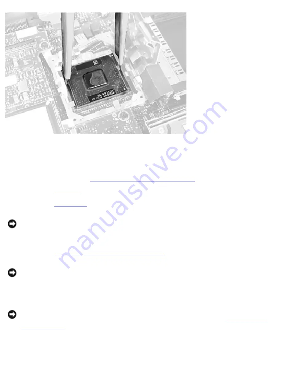
5.  Remove the microprocessor module. 

NOTICE: 

To avoid damage to the microprocessor, hold the screwdriver so that it is 

perpendicular to the microprocessor when removing the cam lock screw (see "

Microprocessor 

Cam Lock Screw

"). 

a.  Loosen the microprocessor socket cam lock screw. The location of the screw and the 

file:///I|/SERVICE%20MANUALS/DELL%20MANUALS/L...Latitude/C810/C810_SERVICE_MANUAL/2e40520.htm (25 of 46)6/21/2004 1:32:50 AM

Содержание Latitude C810

Страница 1: ...Thank you for purchasing this Factory Service Manual CD DVD from servicemanuals4u com Please check out our eBay auctions for more great deals on Factory Service Manuals servicemanuals4u ...

Страница 2: ... Assembly Battery and Modular Bay Latch Assemblies Battery Charger Board LED Board Fan Assembly RJ 11 RJ 45 Board Notes Notices and Cautions NOTE A NOTE indicates important information that helps you make better use of your computer NOTICE A NOTICE indicates either potential damage to hardware or loss of data and tells you how to avoid the problem CAUTION A CAUTION indicates a potentially hazardou...

Страница 3: ... and Latitude are trademarks of Dell Computer Corporation Other trademarks and trade names may be used in this document to refer to either the entities claiming the marks and names or their products Dell Computer Corporation disclaims any proprietary interest in trademarks and trade names other than its own June 2001 P N 2E405 Rev A00 file I SERVICE 20MANUALS DELL 20MANUALS LA ok Latitude C810 C81...

Страница 4: ...the computer cover 2 Save any work in progress and close all open application programs 3 Turn off the computer and all attached devices NOTE Before turning off the computer make sure the computer is not in a power management mode 4 Make sure the computer is undocked 5 Disconnect the computer from the electrical outlet 6 To avoid possible damage to the system board wait 10 to 20 seconds and then di...

Страница 5: ...chassis 13 Handle components and cards by their edges and avoid touching pins and contacts Recommended Tools The procedures in this manual require the following tools 1 magnetized Phillips screwdriver Small flat blade screwdriver Small plastic scribe Microprocessor extractor Nonmarring tool Flash BIOS upgrade program diskette or CD provided when needed to upgrade the system BIOS System Orientation...

Страница 6: ... replacing components photocopy the placemat as a tool to lay out and keep track of the component screws The placemat provides the number of screws and the sizes Screw Identification file I SERVICE 20MANUALS DELL 20MANUALS LA Latitude C810 C810_SERVICE_MANUAL 2e40510 htm 3 of 5 6 21 2004 1 32 43 AM ...

Страница 7: ...ase Assembly M2 5 x 20 mm 4 each one in memory door and one in mini PCI door Display to Base M2 5 x 6 mm 3 each 2 at back of system 1 at flex cable strain relief Display Bezel Rubber screw covers 4 each Plastic screw covers 2 each M2 5 x 4 mm 6 each Display Panel to Display Mounting Bracket M2 0 x 3 mm 6 each Flex Cable Mounting Bracket to Top Cover M2 5 x 4 mm 1 each Video Graphics Board M2 5 x 8...

Страница 8: ... x 4 mm 2 each System Board M2 5 x 4 mm captive washer 3 each M2 5 x 20 mm 1 each LED Board M2 0 x 4 mm 2 each Fan Assembly M2 0 x 4 mm 3 each RJ 11 RJ 45 Board Assembly M2 5 x 4 mm 1 each Back to Contents Page file I SERVICE 20MANUALS DELL 20MANUALS LA Latitude C810 C810_SERVICE_MANUAL 2e40510 htm 5 of 5 6 21 2004 1 32 43 AM ...

Страница 9: ...eyboard Assembly Display and Bezel Assemblies Microprocessor Thermal Cooling Assembly Microprocessor Module Video Graphics Board Palmrest Assembly Reserve Battery System Board Assembly Battery and Modular Bay Latch Assemblies Battery Charger Board LED Board Fan Assembly RJ 11 RJ 45 Board System Components Exploded View file I SERVICE 20MANUALS DELL 20MANUALS L Latitude C810 C810_SERVICE_MANUAL 2e4...

Страница 10: ...Removing and Replacing Parts Dell Latitude C810 Service Manual file I SERVICE 20MANUALS DELL 20MANUALS L Latitude C810 C810_SERVICE_MANUAL 2e40520 htm 2 of 46 6 21 2004 1 32 49 AM ...

Страница 11: ...e removal procedure in reverse order Hard Drive NOTICE Disconnect the computer and attached devices from the electrical outlet and remove any installed batteries NOTICE To avoid ESD ground yourself by using a wrist grounding strap or by periodically touching unpainted metal on the computer NOTICE The hard drive is very sensitive to shock Handle it by its edges do not squeeze the top of the case an...

Страница 12: ...ith the computer case 2 Push down on the drive until it snaps into place 3 Replace the screw in the hard drive door Fixed Optical Drive NOTICE Disconnect the computer and attached devices from the electrical outlet and remove any installed batteries NOTICE To avoid ESD ground yourself by using a wrist grounding strap or by periodically touching unpainted metal on the computer Fixed Optical Drive f...

Страница 13: ...re removing the fixed optical drive 3 Turn the computer over pull out the pull tab and use the pull tab to remove the fixed optical drive Memory Module NOTICE Disconnect the computer and any attached devices from electrical outlets and remove any installed batteries NOTICE To avoid ESD ground yourself by using a wrist grounding strap or by periodically touching unpainted metal on the computer file...

Страница 14: ...Memory Module Cover 1 Follow the instructions in Preparing to Work Inside the Computer 2 Remove the screw 3 Disengage the metal tabs at the opposite end of the cover Memory Modules file I SERVICE 20MANUALS DELL 20MANUALS L Latitude C810 C810_SERVICE_MANUAL 2e40520 htm 6 of 46 6 21 2004 1 32 49 AM ...

Страница 15: ...ave one memory module install it in the socket labeled DIMM A Install a second memory module in the socket labeled DIMM B NOTE Memory modules are keyed to fit into their sockets in only one direction 2 Insert the memory module s edge connector into the socket slot at a 45 degree angle and press the module firmly into the slot 3 Pivot the module down until it clicks into place If you do not hear a ...

Страница 16: ...a modem and NIC combination or a wireless NIC A modem NIC or modem and NIC combination must be connected to the wiring harness as appropriate a wireless NIC must be connected to the system s internal antenna NOTICE Disconnect the computer and attached devices from electrical outlets and remove any installed batteries NOTICE To avoid ESD ground yourself by using a wrist grounding strap or by period...

Страница 17: ...ed cables Replacing the Mini PCI Card Assembly 1 Align the Mini PCI Card assembly with the socket at a 45 degree angle and press the Mini PCI Card into the socket 2 Depending on what type of Mini PCI Card you are installing either connect the wiring harness to the Mini PCI Card assembly or connect the mini coax antenna cable from the Mini PCI Card assembly to the internal antenna NOTICE The connec...

Страница 18: ...placing Parts Dell Latitude C810 Service Manual Mini PCI Wireless NIC Assembly Using Antenna Cable file I SERVICE 20MANUALS DELL 20MANUALS L Latitude C810 C810_SERVICE_MANUAL 2e40520 htm 10 of 46 6 21 2004 1 32 49 AM ...

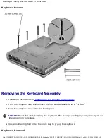
Страница 19: ... so it does not interfere with the cover 3 Pivot the Mini PCI Card assembly down until it clicks into place 4 Replace the Mini PCI Card assembly cover Keyboard Assembly NOTICE Disconnect the computer and attached devices from electrical outlets and remove any installed batteries NOTICE To avoid ESD ground yourself by using a wrist grounding strap or by periodically touching unpainted metal on the ...

Страница 20: ...emove the four screws labeled with a circle K 3 Turn the computer over and open the display NOTICE Be careful when handling the keyboard The keycaps are fragile easily dislodged and time consuming to replace 4 Use a nonmarring tool under the blank key to pry up the keyboard Keyboard Removal file I SERVICE 20MANUALS DELL 20MANUALS L Latitude C810 C810_SERVICE_MANUAL 2e40520 htm 12 of 46 6 21 2004 1...

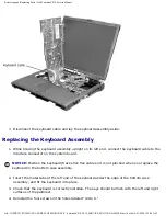
Страница 21: ... slide it slightly toward the right side of the computer to disengage the tabs at the left end 6 Pivot the keyboard and balance it upright on the left side of the computer Keyboard Cable file I SERVICE 20MANUALS DELL 20MANUALS L Latitude C810 C810_SERVICE_MANUAL 2e40520 htm 13 of 46 6 21 2004 1 32 49 AM ...

Страница 22: ...rack stick flex cable so it is not pinched when you replace the keyboard in the bottom case assembly 2 Insert the metal tabs at the left end of the keyboard under the edge of the bottom case assembly and fit the keyboard into place 3 Check that the keyboard is correctly installed The keys should be flush with the left and right surfaces of the palmrest 4 Reinstall the four screws in the holes labe...

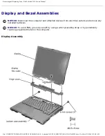
Страница 23: ...hed devices from electrical outlets and remove any installed batteries NOTICE To avoid ESD ground yourself by using a wrist grounding strap or by periodically touching unpainted metal on the computer Display Assembly file I SERVICE 20MANUALS DELL 20MANUALS L Latitude C810 C810_SERVICE_MANUAL 2e40520 htm 15 of 46 6 21 2004 1 32 49 AM ...

Страница 24: ...ng to Work Inside the Computer 2 Use a nonmarring tool to loosen the hinge cover at the back and at each side of the computer 3 Open the display and lift off the hinge cover Removing the Display Assembly Display Assembly file I SERVICE 20MANUALS DELL 20MANUALS L Latitude C810 C810_SERVICE_MANUAL 2e40520 htm 16 of 46 6 21 2004 1 32 49 AM ...

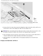
Страница 25: ...Service Manual 1 Remove the hinge cover NOTICE Make sure you remove the flex cable before you remove the display assembly Flex Cable file I SERVICE 20MANUALS DELL 20MANUALS L Latitude C810 C810_SERVICE_MANUAL 2e40520 htm 17 of 46 6 21 2004 1 32 49 AM ...

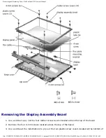
Страница 26: ...nnector not in the middle Pressing the middle of the connector can damage fragile components 3 Open the display and from the back of the computer remove the two screws labeled with a circle D that secure the display assembly to the bottom case assembly 4 With the display in an upright position lift the display assembly from the bottom case assembly Display Assembly Bezel and Panel file I SERVICE 2...

Страница 27: ...bber screw covers located across the top of the bezel 2 Remove the four 4 mm screws located across the top of the bezel 3 Use a scribe at the indentations to pry out the two plastic screw covers located at the bottom of file I SERVICE 20MANUALS DELL 20MANUALS L Latitude C810 C810_SERVICE_MANUAL 2e40520 htm 19 of 46 6 21 2004 1 32 50 AM ...

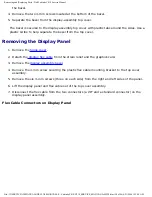
Страница 28: ...y flex cable from the strain relief and the graphics card 3 Remove the display assembly bezel 4 Remove the 4 mm screw securing the plastic flex cable mounting bracket to the top cover assembly 5 Remove the six 3 mm screws three on each side from the right and left sides of the panel 6 Lift the display panel and flex cable out of the top cover assembly 7 Disconnect the flex cable from the two conne...

Страница 29: ...able to the two connectors on the back of the display panel 2 Place the display panel assembly in the top cover taking care that the flex cable is in place and is not crushed or crimped 3 Reinstall the 4 mm screw that secures the flex cable mounting bracket to the top cover file I SERVICE 20MANUALS DELL 20MANUALS L Latitude C810 C810_SERVICE_MANUAL 2e40520 htm 21 of 46 6 21 2004 1 32 50 AM ...

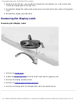
Страница 30: ...o the graphics card 6 Reinstall the display assembly bezel Removing the Display Latch Removing the Display Latch 1 Remove the hinge cover 2 Detach the display flex cable from the strain relief and the graphics card 3 Remove the display assembly bezel 4 Remove the display panel from the top cover 5 Remove the display latch by unsnapping the latch and captive spring file I SERVICE 20MANUALS DELL 20M...

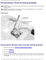
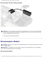
Страница 31: ...al on the computer Retaining Clip Removing the Microprocessor Thermal Cooling Assembly 1 Follow the instructions in Preparing to Work Inside the Computer 2 Remove the keyboard 3 Remove the hinge cover 4 Insert a flat blade screwdriver into the latch mechanism at the left side of the microprocessor retaining clip Pry open the clip by pivoting the top of the screwdriver toward the right side of the ...

Страница 32: ... transfer capability of the thermal pads 5 Lift out the thermal cooling assembly Microprocessor Module NOTICE Disconnect the computer and attached devices from electrical outlets and remove any installed batteries NOTICE To avoid ESD ground yourself by using a wrist grounding strap or by periodically touching unpainted metal on the computer Microprocessor Module file I SERVICE 20MANUALS DELL 20MAN...

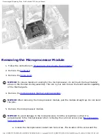
Страница 33: ...ity of the thermal pads 4 Remove the microprocessor thermal cooling assembly NOTICE When removing the microprocessor module pull the module straight up Do not bend the pins 5 Remove the microprocessor module NOTICE To avoid damage to the microprocessor hold the screwdriver so that it is perpendicular to the microprocessor when removing the cam lock screw see Microprocessor Cam Lock Screw a Loosen ...

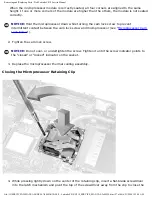
Страница 34: ...kette or CD with the replacement microprocessor you must update the BIOS after replacing the microprocessor module For instructions on updating or reflashing the BIOS see the Dell Portable Computer BIOS Update Guide NOTICE Proper seating of the microprocessor module does not require force NOTICE A microprocessor module that is not properly seated can result in an intermittent connection and subseq...

Страница 35: ...r see Microprocessor Cam Lock Screw 2 Tighten the cam lock screw NOTICE Do not over or undertighten the screw Tighten it until the screw indicator points to the closed or locked indicator on the socket 3 Replace the microprocessor thermal cooling assembly Closing the Microprocessor Retaining Clip 4 While pressing lightly down on the center of the retaining clip insert a flat blade screwdriver into...

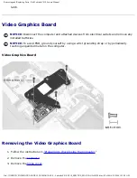
Страница 36: ... To avoid ESD ground yourself by using a wrist grounding strap or by periodically touching unpainted metal on the computer Video Graphics Board Removing the Video Graphics Board 1 Follow the instructions in Preparing to Work Inside the Computer 2 Remove the keyboard 3 Remove the hinge cover file I SERVICE 20MANUALS DELL 20MANUALS L Latitude C810 C810_SERVICE_MANUAL 2e40520 htm 28 of 46 6 21 2004 1...

Страница 37: ...seat the board in its connector NOTICE Make sure the board is correctly and firmly seated before continuing Failure to do so will cause intermittent video failures 2 Replace the three screws Palmrest Assembly NOTICE Disconnect the computer and attached devices from electrical outlets and remove any installed batteries NOTICE To avoid ESD ground yourself by using a wrist grounding strap or by perio...

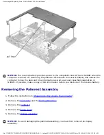
Страница 38: ...s in NVRAM If possible make a copy of this information before you disconnect the reserve battery Removing the Palmrest Assembly 1 Follow the instructions in Preparing to Work Inside the Computer 2 Remove the hard drive and the fixed optical drive 3 Remove the keyboard 4 Remove the hinge cover 5 Remove the display assembly NOTICE To avoid damaging the palmrest assembly you must first remove the dis...

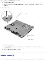
Страница 39: ... the palmrest to the computer Palmrest Screws 8 Turn the computer over 9 Use the pull loop to disconnect the palmrest flex cable from the touch pad connector on the system board 10 Carefully lift out the palmrest assembly Reserve Battery file I SERVICE 20MANUALS DELL 20MANUALS L Latitude C810 C810_SERVICE_MANUAL 2e40520 htm 31 of 46 6 21 2004 1 32 50 AM ...

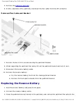
Страница 40: ...o the computer s RTC and NVRAM when the computer is turned off Removing the battery causes the computer to lose the date and time information as well as all user specified parameters in NVRAM If possible make a copy of this information before you remove the reserve battery Removing the Reserve Battery 1 Follow the instructions in Preparing to Work Inside the Computer 2 Remove the keyboard 3 Remove...

Страница 41: ...ket and turn it over 9 Disconnect the reserve battery cable 10 Remove the reserve battery a Pry the reserve battery free from the metal palmrest bracket b Remove the foam pad remnants from the palmrest bracket Replacing the Reserve Battery 1 Seat the reserve battery and press it into place 2 Connect the reserve battery cable 3 Place the palmrest bracket loosely in the palmrest and connect the palm...

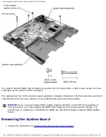
Страница 42: ... NOTICE Disconnect the computer and attached devices from electrical outlets and remove any installed batteries NOTICE To avoid ESD ground yourself by using a wrist grounding strap or by periodically touching unpainted metal on the computer System Board Screws file I SERVICE 20MANUALS DELL 20MANUALS L Latitude C810 C810_SERVICE_MANUAL 2e40520 htm 34 of 46 6 21 2004 1 32 50 AM ...

Страница 43: ... tag number to the replacement system board assembly NOTICE If you received a flash BIOS update program diskette or CD with the replacement microprocessor you must update the BIOS after replacing the microprocessor module For instructions on updating or reflashing the BIOS see the Dell Portable Computer BIOS Update Guide Removing the System Board 1 Follow the instructions in Preparing to Work Insi...

Страница 44: ... palmrest assembly 9 Remove the video graphics board 10 Remove the microprocessor thermal cooling assembly 11 If migrating the microprocessor remove the microprocessor module 12 Remove the three 4 mm captive washer screws from the system board 13 Remove the 20 mm screw from the center of the LED board 14 Lift the front of the system board and work it out of the back panel System Board file I SERVI...

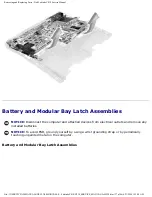
Страница 45: ...vices from electrical outlets and remove any installed batteries NOTICE To avoid ESD ground yourself by using a wrist grounding strap or by periodically touching unpainted metal on the computer Battery and Modular Bay Latch Assemblies file I SERVICE 20MANUALS DELL 20MANUALS L Latitude C810 C810_SERVICE_MANUAL 2e40520 htm 37 of 46 6 21 2004 1 32 50 AM ...

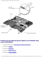
Страница 46: ...ay Latch Assemblies 1 Follow the instructions in Preparing to Work Inside the Computer 2 Remove the keyboard 3 Remove the hinge cover 4 Remove the display assembly 5 Remove the palmrest assembly file I SERVICE 20MANUALS DELL 20MANUALS L Latitude C810 C810_SERVICE_MANUAL 2e40520 htm 38 of 46 6 21 2004 1 32 50 AM ...

Страница 47: ...th the two bumps is facing the back of the case and the surface with the wear ribs is facing the bottom of the case 7 Hold the upper latch assembly in place while you snap the new latch button in from underneath the base making certain the snap tabs are fully engaged in the slider 8 Ensure that the newly installed latch assembly moves smoothly and freely when pushed and released Battery Charger Bo...

Страница 48: ...mrest assembly 6 Remove the video graphics board 7 Lift the battery charger board out of the system board connector Replacing the Battery Charger Board Align the screw holes on the battery charger board with the screw holes on the bottom case assembly see Battery Charger Board and then press the battery charger board down into its connector file I SERVICE 20MANUALS DELL 20MANUALS L Latitude C810 C...

Страница 49: ...teries NOTICE To avoid ESD ground yourself by using a wrist grounding strap or by periodically touching unpainted metal on the computer LED Board Removing the LED Board 1 Follow the instructions in Preparing to Work Inside the Computer 2 Remove the hinge cover file I SERVICE 20MANUALS DELL 20MANUALS L Latitude C810 C810_SERVICE_MANUAL 2e40520 htm 41 of 46 6 21 2004 1 32 50 AM ...

Страница 50: ...ard into its connector 2 Replace the two 4 mm screws Fan Assembly NOTICE Disconnect the computer and attached devices from electrical outlets and remove any installed batteries NOTICE To avoid ESD ground yourself by using a wrist grounding strap or by periodically touching unpainted metal on the computer Fan Assembly Removing the Fan Assembly file I SERVICE 20MANUALS DELL 20MANUALS L Latitude C810...

Страница 51: ...connect the shorter cable to the connector closest to the fan assembly Route both cables so that they will not be pinched by the thermal cooling assembly RJ 11 RJ 45 Board NOTICE Disconnect the computer and attached devices from electrical outlets and remove any installed batteries NOTICE To avoid ESD ground yourself by using a wrist grounding strap or by periodically touching unpainted metal on t...

Страница 52: ...if necessary by slipping a nonmarring tool into the cutout at the top and pivoting the tool up to disengage the inner securing tab To replace a connector cover orient the cover notch side up and snap it into the connector cutout RJ 11 RJ 45 Board file I SERVICE 20MANUALS DELL 20MANUALS L Latitude C810 C810_SERVICE_MANUAL 2e40520 htm 44 of 46 6 21 2004 1 32 50 AM ...

Страница 53: ...s fragile pull it back only far enough to remove the board assembly 4 Reach into the enclosure and while pulling the tall plastic tab away from the board assembly to release it lift out the assembly When replacing the RJ 11 RJ 45 board assembly protect the wiring harness by routing it between the plastic posts RJ 11 RJ 45 Board Harness Routing file I SERVICE 20MANUALS DELL 20MANUALS L Latitude C81...

Страница 54: ...Removing and Replacing Parts Dell Latitude C810 Service Manual Back to Contents Page file I SERVICE 20MANUALS DELL 20MANUALS L Latitude C810 C810_SERVICE_MANUAL 2e40520 htm 46 of 46 6 21 2004 1 32 50 AM ...

Отзывы: