Some of the computer
’
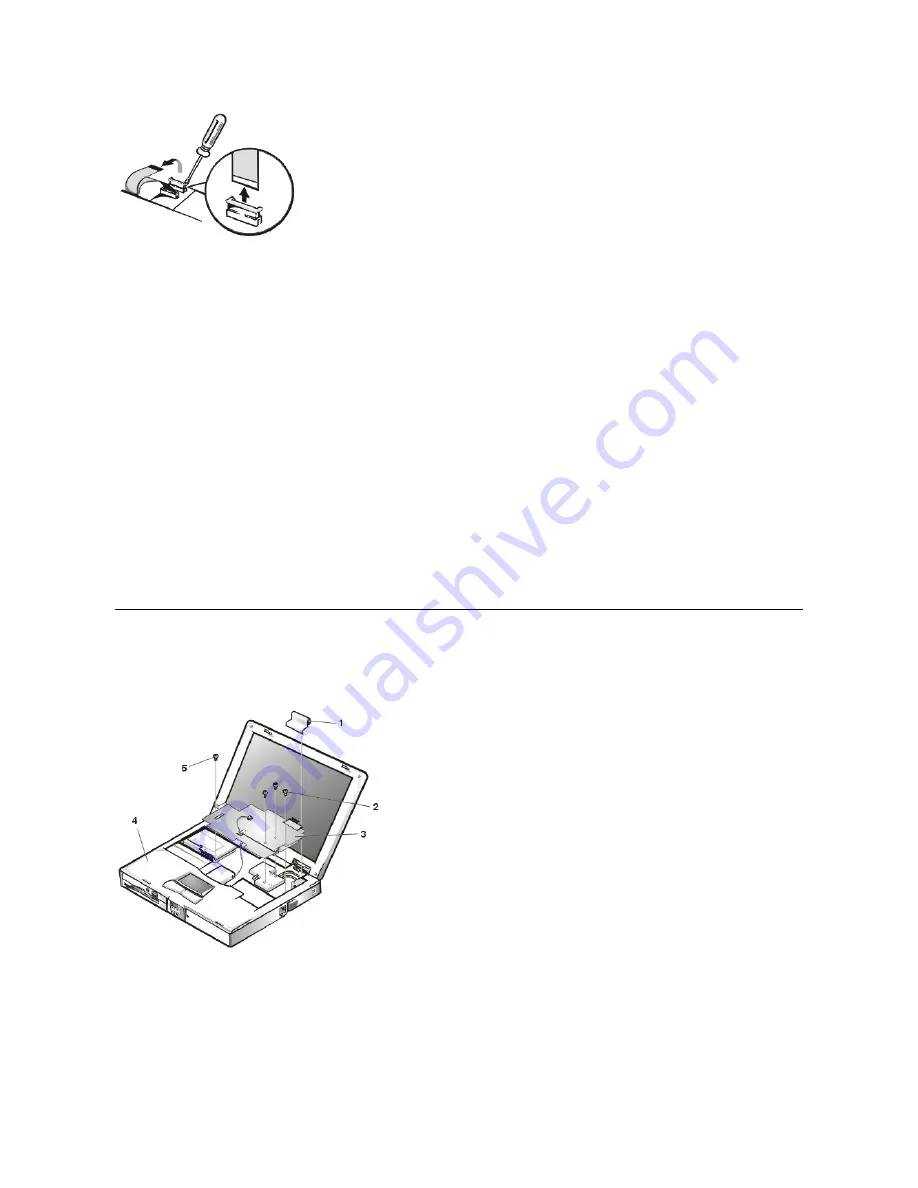
s interface connectors are ZIF connectors. These connectors are not removable; they must be released (see Figure 18) to
disconnect a cable from them.
To disconnect a cable from a ZIF connector, perform the following steps:
1.
Insert a small flat-blade screwdriver or dental pick under the movable part of the connector.
For most ZIFs, carefully pry up one end of the movable part of the connector and then the other end. Some ZIFs may need to be lifted in the
center.
2.
Pull up gently on the movable part of the connector until the cable is released.
3.
Grasp the cable and pull it out of the connector.
To reconnect an interface cable to a ZIF connector, perform the following steps:
1.
Use the flat-blade screwdriver or dental pick to open the movable part of the ZIF connector.
2.
Orient the end of the cable with the ZIF connector, and insert the end of the cable into the connector.
3.
While holding the cable in place, close the ZIF connector.
To ensure a firm connection, make sure the ZIF connector is completely closed
.
Thermal Shield and Internal Modem Removal
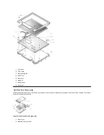
The thermal shield (see Figure 19) serves as a heat shield for the system board, as well as an EMI fence for the processor board.
Figure 19. Thermal Shield/Internal Modem Components
NOTICE: ZIF connectors are fragile. To avoid breaking the connectors, touch them carefully. Do not apply too much pressure to the
movable part of the connector when opening or closing it.
1
Right hinge cover
2
4-mm screws (4)
3
Thermal shield
4
Palmrest assembly
5
K-head 4-
mm screw
Содержание Inspiron 7500
Страница 6: ...Back to Contents Page AC Adapter Dell Inspiron 7500 ...
Страница 7: ...Back to Contents Page Audio Jacks Dell Inspiron 7500 ...
Страница 10: ...Back to Contents Page Component Locations Back View Dell Inspiron 7500 ...
Страница 12: ...Back to Contents Page Battery Charge Gauge Dell Inspiron 7500 ...
Страница 13: ...Back to Contents Page Removing and Installing a Battery Dell Inspiron 7500 ...
Страница 26: ...Back to Contents Page ...
Страница 38: ...Exploded View of 13 3 Inch Display Assembly Dell Inspiron 7500 ...
Страница 39: ...Exploded View of 14 1 Inch Display Assembly Dell Inspiron 7500 ...
Страница 40: ...Back to Contents Page Exploded View of 15 Inch SXGA Display Assembly Dell Inspiron 7500 New artwork pending ...
Страница 42: ...Back to Contents Page Exploded View of 15 4 Inch SXGA Display Assembly Dell Inspiron 7500 New artwork pending ...
Страница 44: ...Back to Contents Page Exploded View of Computer Dell Inspiron 7500 ...
Страница 45: ...Back to Contents Page Exploded View of Palmrest Assembly Dell Inspiron 7500 Back to Contents Page ...
Страница 47: ...Back to Contents Page Component Locations Front View Dell Inspiron 7500 New artwork pending ...
Страница 54: ...Back to Contents Page I O Connectors Dell Inspiron 7500 ...
Страница 60: ...Back to Contents Page 30 Cone of Infrared Light Dell Inspiron 7500 ...
Страница 64: ...Back to Contents Page Embedded Numeric Keypad Dell Inspiron 7500 ...
Страница 88: ...system You can also double click the PC Card icon on the Windows 98 desktop Back to Contents Page ...
Страница 89: ...Back to Contents Page PC Card Slots Dell Inspiron 7500 ...
Страница 103: ...Back to Contents Page Removing the Memory Module Dell Inspiron 7500 ...
Страница 104: ...Back to Contents Page Removing the Memory Module Cover Dell Inspiron 7500 ...
Страница 136: ...Back to Contents Page Removing the Hard Disk Drive Dell Inspiron 7500 ...
Страница 138: ...Back to Contents Page Removing Devices From the Media Bay Dell Inspiron 7500 ...
Страница 140: ...Back to Contents Page Security Cable Slot Dell Inspiron 7500 ...
Страница 159: ...Back to Contents Page Touch Pad Dell Inspiron 7500 ...
Страница 162: ...8 Unlatch the display assembly and lift the assembly off the computer base Back to Contents Page ...


