background image

Steps

1. Peel the tape that secures the display cable to the system board.
2. Open the latch, and disconnect the display cable from the system board.
3. Remove the display cable from the routing guide on the palm-rest and keyboard assembly.
4. Remove the four screws (M2.5x3.5) that secure the display hinges to the palm-rest and keyboard assembly.
5. Lift at an angle and slide the display assembly off the palm-rest and keyboard assembly.

Installing the display assembly

Prerequisites

If you are replacing a component, remove the existing component before performing the installation procedure.

About this task

The following image indicates the location of the display assembly and provides a visual representation of the installation
procedure.

40

Removing and installing components

Содержание Inspiron 7415 2-in-1

Страница 1: ...Inspiron 7415 2 in 1 Service Manual Regulatory Model P147G Regulatory Type P147G001 May 2021 Rev A01 ...

Страница 2: ...ential damage to hardware or loss of data and tells you how to avoid the problem WARNING A WARNING indicates a potential for property damage personal injury or death 2021 Dell Inc or its subsidiaries All rights reserved Dell EMC and other trademarks are trademarks of Dell Inc or its subsidiaries Other trademarks may be trademarks of their respective owners ...

Страница 3: ...tery 16 Installing the 3 cell or 4 cell battery 18 Coin cell battery 20 Removing the coin cell battery 20 Installing the coin cell battery 21 Memory module 22 Removing the memory module 22 Installing the memory module 23 Wireless card 25 Removing the wireless card 25 Installing the wireless card 26 Solid state drive 27 Removing the M 2 2280 solid state drive 27 Installing the M 2 2280 solid state ...

Страница 4: ... Video drivers 60 Wireless and Bluetooth drivers 60 Chapter 4 System setup 61 BIOS overview 61 Entering BIOS setup program 61 Navigation keys 61 Boot Sequence 61 One time boot menu 62 System setup options 62 System and setup password 65 Assigning a system setup password 66 Deleting or changing an existing system setup password 66 Clearing CMOS settings 67 Clearing BIOS System Setup and System pass...

Страница 5: ...Chapter 6 Getting help and contacting Dell 73 Contents 5 ...

Страница 6: ...r computer WARNING Before working inside your computer read the safety information that is shipped with your computer For more safety best practices see the Regulatory Compliance home page at www dell com regulatory_compliance WARNING Disconnect your computer from all power sources before opening the computer cover or panels After you finish working inside the computer replace all covers panels an...

Страница 7: ...son some previously approved methods of handling parts are no longer applicable Two recognized types of ESD damage are catastrophic and intermittent failures Catastrophic Catastrophic failures represent approximately 20 percent of ESD related failures The damage causes an immediate and complete loss of device functionality An example of catastrophic failure is a memory DIMM that has received a sta...

Страница 8: ...ounds if the test fails Insulator Elements It is critical to keep ESD sensitive devices such as plastic heat sink casings away from internal parts that are insulators and often highly charged Working Environment Before deploying the ESD Field Service kit assess the situation at the customer location For example deploying the kit for a server environment is different than for a desktop or portable ...

Страница 9: ...eep the load close The closer it is to your spine the less force it exerts on your back 5 Keep your back upright whether lifting or setting down the load Do not add the weight of your body to the load Avoid twisting your body and back 6 Follow the same techniques in reverse to set the load down After working inside your computer About this task CAUTION Leaving stray or loose screws inside your com...

Страница 10: ...d NOTE Some computers have magnetic surfaces Ensure that the screws are not left attached to such surfaces when replacing a component NOTE Screw color may vary with the configuration ordered Table 1 Screw list Component Secured to Screw type Quantity Screw image Base cover Palm rest and keyboard assembly M2x4 4 Battery Palm rest and keyboard assembly M2x3 5 For computers shipped with a 4 cell batt...

Страница 11: ...alm rest and keyboard assembly M2 5x3 5 4 Power button Power button with fingerprint reader Palm rest and keyboard assembly M1 6X2 2 USB Type C bracket Palm rest and keyboard assembly M2 5x4 5 2 System board Palm rest and keyboard assembly M2x1 8 2 Major components of Inspiron 7415 2 in 1 The following image shows the major components of Inspiron 7415 2 in 1 Removing and installing components 11 ...

Страница 12: ... keyboard assembly 15 Solid state drive bracket 16 M 2 2280 solid state drive 17 Coin cell battery 18 I O board 19 Wireless card bracket 20 Wireless card 21 Fan NOTE Dell provides a list of components and their part numbers for the original system configuration purchased These parts are available according to warranty coverages purchased by the customer Contact your Dell sales representative for p...

Страница 13: ...isites 1 Follow the procedure in Before working inside your computer About this task The following images indicate the location of the base cover and provide a visual representation of the removal procedure Removing and installing components 13 ...

Страница 14: ...he base cover to the palm rest and keyboard assembly NOTE Upon loosening the three captive screws the base cover will open up creating a gap between the base cover and the palm rest assembly 3 Starting from the top left corner pry the base cover to release the base cover from the palm rest and keyboard assembly 14 Removing and installing components ...

Страница 15: ...allation procedure Steps 1 Align the screw holes on the base cover with the screw holes on the palm rest and keyboard assembly and then snap the base cover into place 2 Replace the four screws M2x4 that secure the base cover to the palm rest and keyboard assembly 3 Tighten the three captive screws that secure the base cover to the palm rest and keyboard assembly Next steps 1 Follow the procedure i...

Страница 16: ... any screws during the servicing of this product are not lost or misplaced to prevent accidental puncture or damage to the battery and other system components If the battery gets stuck inside your computer as a result of swelling do not try to release it as puncturing bending or crushing a lithium ion battery can be dangerous In such an instance contact Dell technical support for assistance See ww...

Страница 17: ...if not disconnected earlier 3 Remove the three screws M2x3 that secure the battery to the palm rest and keyboard assembly 4 Lift the battery off the palm rest and keyboard assembly Removing the 4 cell battery About this task The following image indicates the location of the battery and provides a visual representation of the removal procedure Removing and installing components 17 ...

Страница 18: ... the palm rest and keyboard assembly 4 Lift the battery off the palm rest and keyboard assembly Installing the 3 cell or 4 cell battery Installing the 3 cell battery Prerequisites If you are replacing a component remove the existing component before performing the installation procedure About this task The following image indicates the location of the battery and provides a visual representation o...

Страница 19: ... the system board 4 Adhere the tape that secures the battery cable to the system board Installing the 4 cell battery Prerequisites If you are replacing a component remove the existing component before performing the installation procedure About this task The following image indicates the location of the battery and provides a visual representation of the installation procedure Removing and install...

Страница 20: ...he battery cable to the system board Next steps 1 Install the base cover 2 Follow the procedure in After working inside your computer Coin cell battery Removing the coin cell battery Prerequisites 1 Follow the procedure in Before working inside your computer 2 Remove the base cover About this task The following image indicates the location of the coin cell battery and provides a visual representat...

Страница 21: ...embly Installing the coin cell battery Prerequisites If you are replacing a component remove the existing component before performing the installation procedure About this task The following image indicates the location of the coin cell battery and provides a visual representation of the installation procedure Removing and installing components 21 ...

Страница 22: ... Follow the procedure in After working inside your computer Memory module Removing the memory module Prerequisites 1 Follow the procedure in Before working inside your computer 2 Remove the base cover About this task The following image indicates the location of the memory modules and provides a visual representation of the removal procedure 22 Removing and installing components ...

Страница 23: ... module slot NOTE Repeat step 2 to step 3 to remove any other memory modules installed in your computer Installing the memory module Prerequisites If you are replacing a component remove the existing component before performing the installation procedure About this task The following image indicates the location of the memory modules and provides a visual representation of the installation procedu...

Страница 24: ... into the memory module slot 4 Press the memory module down until it clicks into place NOTE If you do not hear the click remove the memory module and reinstall it NOTE Repeat step 2 to step 4 to install any other memory modules in your computer Next steps 1 Install the base cover 2 Follow the procedure in After working inside your computer 24 Removing and installing components ...

Страница 25: ...al representation of the removal procedure Steps 1 Peel the tape that secures the antenna cable to the wireless card bracket 2 Remove the screw M2x3 that secures the wireless card bracket to the wireless card and system board 3 Remove the wireless card bracket from the wireless card 4 Disconnect the antenna cables from the wireless card 5 Slide and remove the wireless card from the wireless card s...

Страница 26: ...ides a visual representation of the installation procedure Steps 1 Connect the antenna cables to the wireless card The following table provides the antenna cable color scheme for the wireless card that is supported by your computer Table 2 Antenna cable color scheme Connectors on the wireless card Antenna cable color Silkscreen marking Main White MAIN white triangle Auxiliary Black AUX black trian...

Страница 27: ...less card and system board 5 Adhere the tape that secures the antenna cable to the wireless card bracket Next steps 1 Install the base cover 2 Follow the procedure in After working inside your computer Solid state drive Removing the M 2 2280 solid state drive Prerequisites 1 Follow the procedure in Before working inside your computer 2 Remove the base cover About this task The following image indi...

Страница 28: ... 2 2280 solid state drive Prerequisites If you are replacing a component remove the existing component before performing the installation procedure About this task This computer supports two solid state drive form factors M 2 2230 M 2 2280 If you are replacing the M 2 2280 solid state drive with an M 2 2230 solid state drive the following images indicate where to install the solid state drive brac...

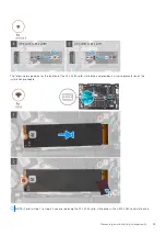
Страница 29: ...e M 2 2280 solid state drive and provides a visual representation of the installation procedure NOTE Perform step 1 to step 4 if you are replacing the M 2 2230 solid state drive with an M 2 2280 solid state drive Removing and installing components 29 ...

Страница 30: ... slot 6 Slide the solid state drive firmly into the solid state drive slot at an angle 7 Replace the screw M2x3 that secures the solid state drive to the solid state drive bracket 8 Adhere the tape that secures the antenna calbe to the palm rest and solid state drive Next steps 1 Install the base cover 2 Follow the procedure in After working inside your computer Removing the M 2 2230 solid state d...

Страница 31: ... solid state drive slot Installing the M 2 2230 solid state drive Prerequisites If you are replacing a component remove the existing component before performing the installation procedure About this task This computer supports two solid state drive form factors M 2 2230 M 2 2280 If you are replacing the M 2 2230 solid state drive with an M 2 2280 solid state drive the following images indicate whe...

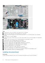
Страница 32: ...e M 2 2230 solid state drive and provides a visual representation of the installation procedure NOTE Perform step 1 to step 4 if you are replacing the M 2 2230 solid state drive with an M 2 2280 solid state drive 32 Removing and installing components ...
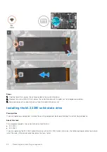
Страница 33: ... drive slot at an angle 7 Replace the screw M2x3 that secures the solid state drive to the solid state drive bracket 8 Adhere the tape that secures the antenna cable to the solid state drive Next steps 1 Install the base cover 2 Follow the procedure in After working inside your computer Speakers Removing the speakers Prerequisites 1 Follow the procedure in Before working inside your computer 2 Rem...

Страница 34: ...entation of the installation procedure Steps 1 Using the alignment posts and rubber grommets place the speakers on the slots of the palm rest and keyboard assembly 2 Route the speaker cable through the routing guides on the palm rest and keyboard assembly 3 Adhere the tapes that secure the speaker cable to the palm rest and keyboard assembly 4 Connect the speaker cable to the system board Next ste...

Страница 35: ...ot during normal operation Allow sufficient time for the heat sink to cool before you touch it 2 Remove the base cover About this task The following image indicates the location of the heat sink and provides a visual representation of the removal procedure NOTE The number of captive screws and the appearance of the heat sink may vary depending on the configuration you ordered Removing and installi...

Страница 36: ...AUTION Incorrect alignment of the heat sink can damage the system board and processor NOTE If either the system board or the heat sink is replaced use the thermal pad paste provided in the kit to ensure that thermal conductivity is achieved About this task The following image indicates the location of the heat sink and provides a visual representation of the installation procedure NOTE The number ...

Страница 37: ...m board 2 In sequential order as indicated on the heat sink tighten the four or seven captive screws that secure the heat sink to the system board Next steps 1 Install the base cover 2 Follow the procedure in After working inside your computer Removing and installing components 37 ...

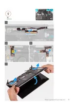
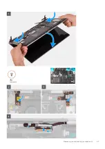
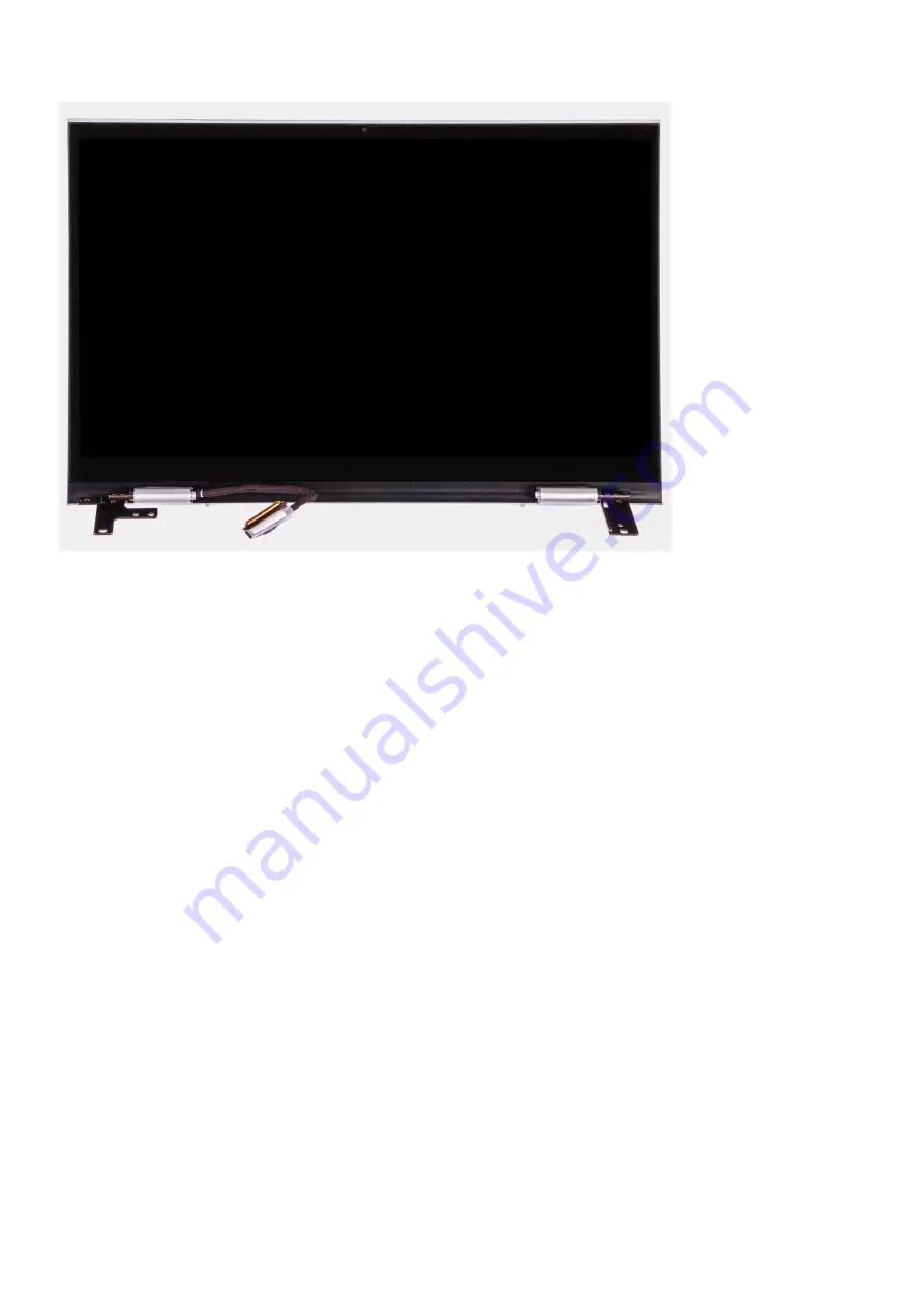
Страница 38: ...ollow the procedure in Before working inside your computer 2 Remove the base cover About this task The following image indicates the location of the display assembly and provides a visual representation of the removal procedure 38 Removing and installing components ...
Страница 39: ...Removing and installing components 39 ...

Страница 40: ...display hinges to the palm rest and keyboard assembly 5 Lift at an angle and slide the display assembly off the palm rest and keyboard assembly Installing the display assembly Prerequisites If you are replacing a component remove the existing component before performing the installation procedure About this task The following image indicates the location of the display assembly and provides a visu...

Страница 41: ...Removing and installing components 41 ...

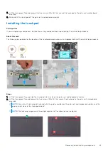
Страница 42: ...cable to the system board Next steps 1 Install the base cover 2 Follow the procedure in After working inside your computer Touchpad Removing the touchpad Prerequisites 1 Follow the procedure in Before working inside your computer 2 Remove the base cover 3 Remove the battery About this task The following image indicates the location of the touchpad and provides a visual representation of the remova...

Страница 43: ...on of the touchpad and provides a visual representation of the installation procedure Steps 1 Lift the transparent flap and slide the touchpad into the slot on the palm rest and keyboard assembly 2 Lift the transparent flap and replace the two screws M2x1 8 that secure the touchpad to the palm rest and keyboard assembly NOTE Ensure that the touchpad is aligned with the guides available on the palm...

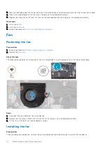
Страница 44: ...an Removing the fan Prerequisites 1 Follow the procedure in Before working inside your computer 2 Remove the base cover About this task The following image indicates the location of the fan and provides a visual representation of the removal procedure Steps 1 Disconnect the fan cable from the system board 2 Remove the two screws M2x3 that secure the fan to the palm rest and keyboard assembly 3 Lif...

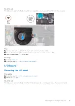
Страница 45: ...palm rest and keyboard assembly 3 Connect the fan cable to the system board Next steps 1 Install the base cover 2 Follow the procedure in After working inside your computer I O board Removing the I O board Prerequisites 1 Follow the procedure in Before working inside your computer 2 Remove the base cover About this task The following image indicates the location of the I O board and provides a vis...

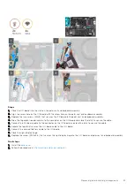
Страница 46: ... cable from the I O board 6 Disconnect the coin cell battery cable from the I O board 7 Remove the two screws M2x3 that secure the I O board to the palm rest and keyboard assembly 8 Slide and lift the I O board off the palm rest and keyboard assembly Installing the I O board Prerequisites If you are replacing a component remove the existing component before performing the installation procedure Ab...

Страница 47: ...and close the latch to secure the cable 5 Connect the I O board cable to the connector on the I O board and close the latch to secure the cable 6 Adhere the tape that secures the I O board cable to the I O board 7 Connect the coin cell battery cable to the I O board 8 Close the right display hinge 9 Replace the screw M2 5x3 5 that secures the right display hinge to the I O board and palm rest and ...

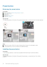
Страница 48: ... removal procedure Steps 1 Remove the two screws M1 6x2 that secure the power button to the palm rest and keyboard assembly 2 Lift the power button off the slot on the palm rest and keyboard assembly Installing the power button Prerequisites If you are replacing a component remove the existing component before performing the installation procedure About this task The following image indicates the ...

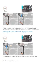
Страница 49: ...l the base cover 5 Follow the procedure in After working inside your computer Removing the power button with fingerprint reader Prerequisites 1 Follow the procedure in Before working inside your computer 2 Remove the base cover 3 Remove the fan 4 Remove the display assembly 5 Remove the I O board About this task The following image indicates the location of the power button with fingerprint reader...

Страница 50: ... power button along with the fingerprint reader cable off the slot on the palm rest and keyboard assembly Installing the power button with fingerprint reader Prerequisites If you are replacing a component remove the existing component before performing the installation procedure 50 Removing and installing components ...

Страница 51: ...e palm rest and keyboard assembly Next steps 1 Install the I O board 2 Install the display assembly 3 Install the fan 4 Install the base cover 5 Follow the procedure in After working inside your computer System board Removing the system board Prerequisites 1 Follow the procedure in Before working inside your computer 2 Remove the base cover 3 Remove the battery 4 Remove the memory modules 5 Remove...

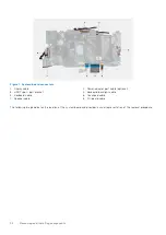
Страница 52: ...l 3 USB Type C port bracket 4 Keyboard backlight cable 5 Keyboard cable 6 Touchpad cable 7 Speaker cable 8 I O board cable The following image indicates the location of the system board and provides a visual representation of the removal procedure 52 Removing and installing components ...
Страница 53: ...Removing and installing components 53 ...

Страница 54: ...connect the display cable from the system board 9 Open the latch and disconnect the keyboard backlight cable from the system board 10 Open the latch and disconnect the keyboard cable from the system board 11 Open the latch and disconnect the touchpad cable from the system board 12 Disconnect the speaker cable from the system board 13 Peel the tape that secures the I O board cable to the system boa...

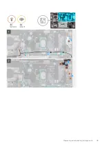
Страница 55: ...ble 2 Power adapter port cable optional 3 USB Type C port bracket 4 Keyboard backlight cable 5 Keyboard cable 6 Touchpad cable 7 Speaker cable 8 I O board cable The following image indicates the location of the system board and provides a visual representation of the installation procedure Removing and installing components 55 ...

Страница 56: ...56 Removing and installing components ...

Страница 57: ...ect the I O board cable to the connector on the system board and close the latch to secure the cable 10 Adhere the tape that secures the I O board cable to the system board 11 Close the left display hinge 12 Replace the two screws M2 5x3 5 that secure the left display hinge to the system board and palm rest and keyboard assembly 13 Align the screw holes on the USB Type C port bracket with the scre...

Страница 58: ...e the M 2 2230 solid state drive or M 2 2280 solid state drive whichever applicable 8 Remove the I O board 9 Remove the speakers 10 Remove the heat sink 11 Remove the fan 12 Remove the touchpad 13 Remove the power button or power button with fingerprint reader 14 Remove the display assembly 15 Remove the system board NOTE The system board can be removed along with the heat sink About this task The...

Страница 59: ...Place the palm rest and keyboard assembly on a clean and flat surface Next steps 1 Install the system board 2 Install the display assembly 3 Install the power button or power button with fingerprint reader 4 Install the touchpad 5 Install the fan 6 Install the heat sink 7 Install the speakers 8 Install the I O board 9 Install the M 2 2230 solid state drive or M 2 2280 solid state drive whichever a...

Страница 60: ...ate from www dell com support Wireless and Bluetooth drivers In the Device Manager check if the network card driver is installed Install the driver updates from www dell com support In the Device Manager check if the Bluetooth driver is installed Install the driver updates from www dell com support 3 60 Device drivers ...

Страница 61: ... setup program About this task Turn on or restart your computer and press F2 immediately Navigation keys NOTE For most of the System Setup options changes that you make are recorded but do not take effect until you restart the system Keys Navigation Up arrow Moves to the previous field Down arrow Moves to the next field Enter Selects a value in the selected field if applicable or follow the link i...

Страница 62: ...available SATA Hard Drive if available Diagnostics The boot sequence screen also displays the option to access the System Setup screen System setup options NOTE Depending on your computer and its installed devices the items listed in this section may or may not appear Table 3 System setup options Main menu Main System Time Displays the current time in hh mm ss format System Date Displays the curre...

Страница 63: ...o configure the operating mode of the integrated SATA hard drive controller Default AHCI Adapter Warnings Allows you to choose if the computer should display warning messages when you use AC adapters that are not supported by your computer Default Enabled Function Key Behavior Allows you to set function key or multimedia key as the default function key behavior Default Multimedia key Keyboard Illu...

Страница 64: ... Default 2 SupportAssist OS Recovery Enables or disables the boot flow for the SupportAssist OS Recovery tool in the even of certain system errors Default Disabled Table 5 System setup options Security menu Security Admin Password Displays if the administrator password is clear or set System Password Displays if the system password is clear or set Default Not Set Asset tag Set your system s Asset ...

Страница 65: ...tem setup options Exit menu Exit Exit Saving Changes Allows you to exit system setup and save your changes Save Change Without Exit Allows you to save your changes without exiting the BIOS setup Exit Discarding Changes Allows you to exit the BIOS setup without saving the changes Load Optimal Defaults Allows you to restore default values for all system setup options Discard Changes Allows you to lo...

Страница 66: ...ges The computer reboots Deleting or changing an existing system setup password Prerequisites Ensure that the Password Status is Unlocked in the System Setup before attempting to delete or change the existing System and Setup password You cannot delete or change an existing System or Setup password if the Password Status is Locked About this task To enter the System Setup press F2 immediately afte...

Страница 67: ...the power button for 15 seconds to drain the flea power 4 Before you turn on your computer follow the steps in Installing the base cover 5 Turn on your computer Clearing BIOS System Setup and System passwords About this task To clear the system or BIOS passwords contact Dell technical support as described at www dell com contactdell NOTE For information on how to reset Windows or application passw...

Страница 68: ... Your Dell computer is uniquely identified by a Service Tag or Express Service Code To view relevant support resources for your Dell computer we recommend entering the Service Tag or Express Service Code at www dell com support For more information on how to find the Service Tag for your computer see Locate the Service Tag for your Dell Laptop System diagnostic lights Battery status light Indicate...

Страница 69: ...this task There are three different types of BIST to check the performance of display power rail and system board These tests are important to evaluate if an LCD or system board needs a replacement 1 M BIST M BIST is the system board built in self test diagnostics tool that improves the diagnostics accuracy of system board embedded controller EC failures M BIST must be manually initiated before PO...

Страница 70: ...de at www dell com support Flashing the BIOS About this task You may need to flash update the BIOS when an update is available or when you replace the system board Follow these steps to flash the BIOS Steps 1 Turn on your computer 2 Go to www dell com support 3 Click Product support enter the Service Tag of your computer and then click Submit NOTE If you do not have the Service Tag use the auto de...

Страница 71: ...odem 3 Turn off the wireless router 4 Wait for 30 seconds 5 Turn on the wireless router 6 Turn on the modem 7 Turn on your computer Drain residual flea power perform hard reset About this task Flea power is the residual static electricity that remains in the computer even after it has been powered off and the battery is removed For your safety and to protect the sensitive electronic components in ...

Страница 72: ...NOTE For more information about performing a hard reset see the knowledge base article SLN85632 at www dell com support 72 Troubleshooting ...

Страница 73: ...ervice Tag or Express Service Code at www dell com support For more information on how to find the Service Tag for your computer see Locate the Service Tag on your computer Dell knowledge base articles for a variety of computer concerns 1 Go to www dell com support 2 On the menu bar at the top of the Support page select Support Knowledge Base 3 In the Search field on the Knowledge Base page type t...

Отзывы: