Running the ePSA diagnostics
1
Power-on the computer.
2
As the computer boots, press the F12 key as the Dell logo appears.
3
On the boot menu screen, select the
Diagnostics
option.
4
Click the arrow key at the bottom left corner.
Diagnostics front page is displayed.
5
Press the arrow in the lower-right corner to go to the page listing.
The items detected are listed.
6
To run a diagnostic test on a specific device, press Esc and click
Yes
to stop the
diagnostic test.
7
Select the device from the left pane and click
Run Tests
.
8
If there are any issues, error codes are displayed.
Note the error code and validation number and contact Dell.
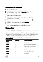
Diagnostics
The computer POST (Power On Self Test) ensures that it meets the basic computer
requirements and the hardware is working appropriately before the boot process
begins. If the computer passes the POST, the computer continues to start in a normal
mode. However, if the computer fails the POST, the computer emits a series of LED
codes during the start-up. The system LED is integrated on the Power button.
The following table shows different light patterns and what they indicate.
Table 7. Diagnostics
Number of LED
flashes
Beep code
Problem description
1 amber
1
BIOS ROM failure
2 amber
2
No memory or RAM detected
3 amber
3
System board: Chipset failure
4 amber
4
Memory or RAM failure
5 amber
5
CMOS battery failure
6 amber
6
Video card/chipset failure
7 amber
7
CPU failure
79
Содержание Inspiron 3472
Страница 14: ...System board components 1 power button cable connector 2 coin cell battery 14 ...
Страница 19: ...2 Release the tabs on the front bezel sequentially from the top by pushing them outwards from the chassis 19 ...
Страница 28: ...2 Remove the two screws 6 32xL6 35 that secure the hard drive assembly to the drive cage 28 ...
Страница 30: ...5 Slide the hard drive out of the hard drive bracket 30 ...
Страница 41: ...2 Remove the coin cell battery from the socket 41 ...
Страница 45: ...5 Slide and remove the wireless card from the wireless card slot 45 ...
Страница 49: ...3 Remove the antenna modules along with the cables off the chassis 49 ...
Страница 53: ...5 Remove the power button module along with its cable through the slot on the front panel 53 ...
Страница 56: ...3 Lift the thermal cooling assembly off the system board 56 ...
Страница 61: ...8 Slide and lift the system board off the chassis 61 ...

