


Replacing the system board
WARNING: Before working inside your computer, read the safety
information that shipped with your computer and follow the steps in
. After working inside your computer, follow
the instructions in
After working inside your computer
. For more safety best
practices, see the Regulatory Compliance home page at
.
NOTE: Your computer’s Service Tag is stored in the system board. You must
enter the Service Tag in the BIOS setup program after you replace the
system board.
NOTE: Replacing the system board removes any changes you have made to
the BIOS using the BIOS setup program. You must make the appropriate
changes again after you replace the system board.
Procedure
1
Align the screw holes on the system board with the screw holes on the palm-rest
assembly.
2
Replace the four screws (M2x2 Big Head) that secure the system board to the
palm-rest assembly.
3
Align the screw holes on the USB Type-C bracket with the screw holes on the
system board and the palm-rest assembly.
4
Replace the two screws (M2x3) that secure the USB Type-C bracket to the
system board and the palm-rest assembly.
5
Align the screw holes on the graphics daughter-board brackets with the screw
holes on the graphics daughter-board and the system board.
6
Replace the four screws (M2x3) that secure the graphics daughter-board
brackets to the graphics daughter-board and the system board.
7
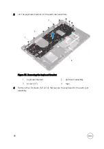
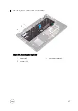
Slide the status-light board cable, keyboard cable, keyboard backlight-cable, and
touch pad cable in to their respective connectors on the system board and close
the latch to secure the cable.
8
Connect the speaker cable to the system board.
9
Connect the power-adapter port cable to the system board.
10
Connect the hard-drive cable to the system board.
83
Содержание Inspiron 17 7000 Series
Страница 28: ...Post requisites 1 Replace the battery 2 Replace the base cover 28 ...
Страница 55: ...4 Lift the fan off the palm rest assembly Figure 19 Removing the fan 1 screws 2 2 fan 3 tape 4 fan cable 55 ...
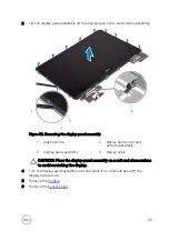
Страница 76: ...8 Lift the display assembly off the palm rest assembly Figure 28 Display assembly 1 display assembly 76 ...
Страница 89: ...12 Replace the base cover 89 ...
Страница 93: ...19 Replace the base cover 93 ...
Страница 99: ...Figure 38 Display back cover and antenna assembly 1 display back cover and antenna assembly 99 ...


