


5. Touchpad
6. Touchpad bracket
7. Power-adapter port
8. Solid-state drive thermal plate
9. M.2 2280 solid-state drive
10. Palm-rest and keyboard assembly
11. Display assembly
12. Memory modules
13. Wireless card
14. Input/Output board
15. System board
16. Fan
17. Heat sink
18. Input output board FFC
19. Hard drive
NOTE:
Dell provides a list of components and their part numbers for the original system configuration purchased. These
parts are available according to warranty coverages purchased by the customer. Contact your Dell sales representative for
purchase options.
Secure Digital Card
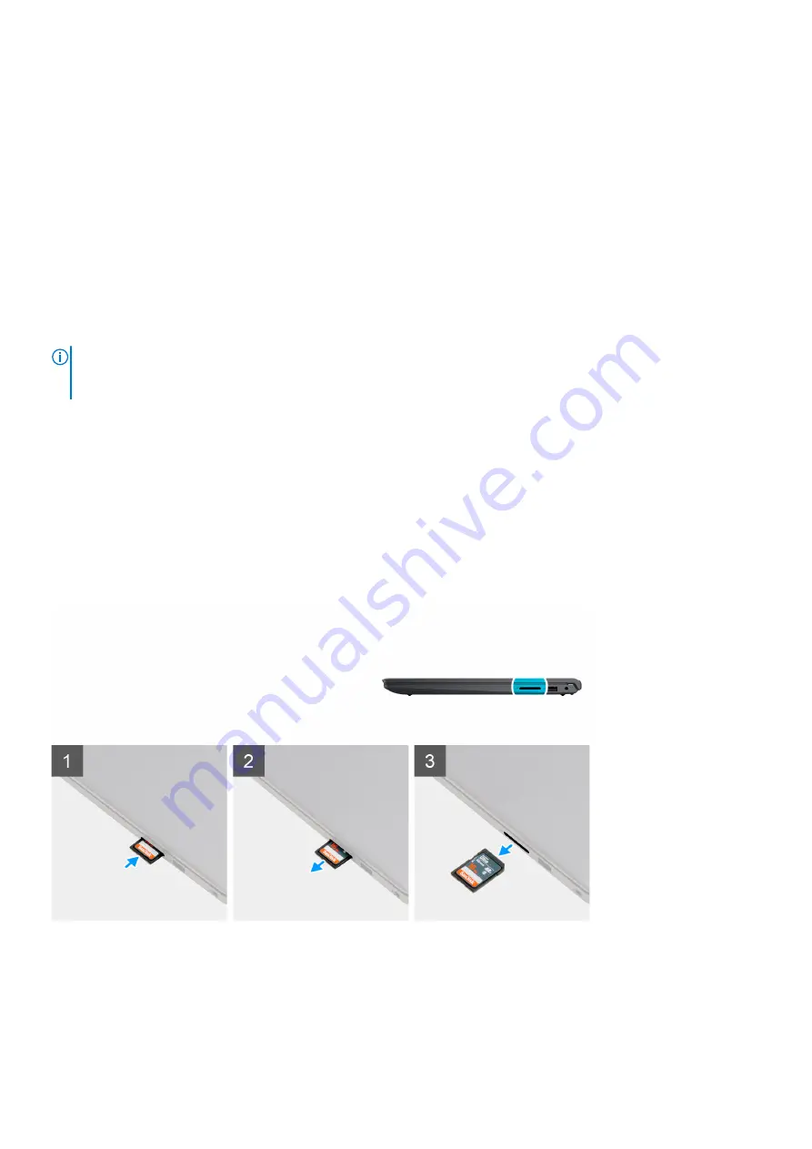
Removing the Secure Digital card
Prerequisites
Before working inside your computer
About this task
Steps
1. Push the secure digital card to release it from the card slot.
2. Slide the secure digital card out of the computer.
Removing and installing components
13