background image

Power button

Removing the power button

Prerequisites

1. Follow the procedure in 

Before working inside your computer

.

2. Enter 

Service Mode

.

3. Remove the 

base cover

.

4. Remove the 

fan

.

5. Remove the 

display assembly

.

6. Remove the 

I/O board

.

About this task

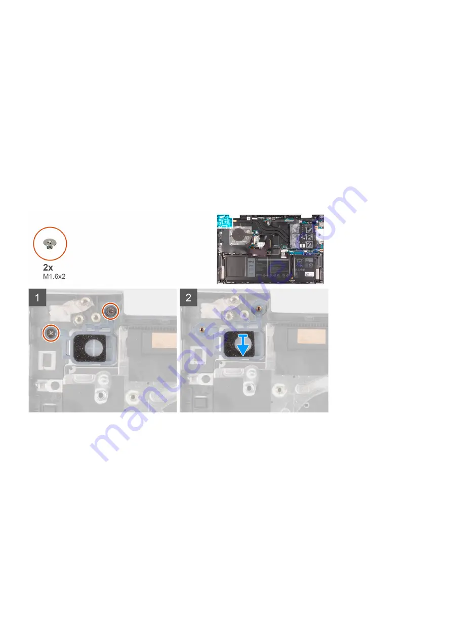
The following image indicates the location of the power button and provides a visual representation of the removal procedure.

Steps

1. Remove the two screws (M1.6x2) that secure the power button to the palm-rest and keyboard assembly.
2. Lift the power button off the slot on the palm-rest and keyboard assembly.

Installing the power button

Prerequisites

If you are replacing a component, remove the existing component before performing the installation procedure.

About this task

The following image indicates the location of the power button and provides a visual representation of the installation
procedure.

50

Removing and installing components

Содержание Inspiron 14 5410

Страница 1: ...Inspiron 14 5410 2 in 1 Service Manual Regulatory Model P147G Regulatory Type P147G002 May 2021 Rev A01 ...

Страница 2: ...ential damage to hardware or loss of data and tells you how to avoid the problem WARNING A WARNING indicates a potential for property damage personal injury or death 2021 Dell Inc or its subsidiaries All rights reserved Dell EMC and other trademarks are trademarks of Dell Inc or its subsidiaries Other trademarks may be trademarks of their respective owners ...

Страница 3: ... or 4 cell battery 16 Installing the 3 cell or 4 cell battery 18 Coin cell battery 20 Removing the coin cell battery 20 Installing the coin cell battery 21 Memory module 22 Removing the memory module 22 Installing the memory module 23 Wireless card 25 Removing the wireless card 25 Installing the wireless card 26 Solid state drive 27 Removing the M 2 2280 solid state drive 27 Installing the M 2 228...

Страница 4: ...mbly 60 Installing the palm rest and keyboard assembly 61 Chapter 3 Device drivers 63 Intel Chipset Software Installation Utility 63 Video drivers 63 Intel Serial IO driver 63 Intel Trusted Execution Engine Interface 63 Intel Virtual Button driver 63 Wireless and Bluetooth drivers 63 Chapter 4 System setup 64 BIOS overview 64 Entering BIOS setup program 64 Navigation keys 64 Boot Sequence 64 One t...

Страница 5: ...ing the operating system 79 Flashing the BIOS 79 Flashing BIOS USB key 80 Backup media and recovery options 80 WiFi power cycle 80 Drain residual flea power perform hard reset 80 Chapter 6 Getting help and contacting Dell 82 Contents 5 ...

Страница 6: ...r computer WARNING Before working inside your computer read the safety information that is shipped with your computer For more safety best practices see the Regulatory Compliance home page at www dell com regulatory_compliance WARNING Disconnect your computer from all power sources before opening the computer cover or panels After you finish working inside the computer replace all covers panels an...

Страница 7: ...s to melt and in the meantime may cause degradation of memory integrity intermittent memory errors etc The more difficult type of damage to recognize and troubleshoot is the intermittent also called latent or walking wounded failure Perform the following steps to prevent ESD damage Use a wired ESD wrist strap that is properly grounded The use of wireless anti static straps is no longer allowed the...

Страница 8: ...eturn the damaged part using the same ESD bag and packaging that the new part arrived in The ESD bag should be folded over and taped shut and all the same foam packing material should be used in the original box that the new part arrived in ESD sensitive devices should be removed from packaging only at an ESD protected work surface and parts should never be placed on top of the ESD bag because onl...

Страница 9: ...ut disconnecting the battery cable from the system board After working inside your computer About this task CAUTION Leaving stray or loose screws inside your computer may severely damage your computer Steps 1 Replace all screws and ensure that no stray screws remain inside your computer 2 Connect any external devices peripherals or cables you removed before working on your computer 3 Replace any m...

Страница 10: ...ave magnetic surfaces Ensure that the screws are not left attached to such surfaces when replacing a component NOTE Screw color may vary with the configuration ordered Table 1 Screw list Component Secured to Screw type Quantity Screw image Base cover Palm rest and keyboard assembly M2x4 4 Battery Palm rest and keyboard assembly M2x3 5 For computers shipped with a 4 cell battery 3 For computers shi...

Страница 11: ...n Power button with fingerprint reader Palm rest and keyboard assembly M1 6X2 2 Power adapter port Palm rest and keyboard assembly 2x3 1 USB Type C bracket Palm rest and keyboard assembly M2 5x4 5 2 System board Palm rest and keyboard assembly M2x1 8 2 Major components of Inspiron 5410 2 in 1 The following image shows the major components of Inspiron 5410 2 in 1 Removing and installing components ...

Страница 12: ...em board 8 Touchpad cable 9 Battery 10 Speakers 11 Touchpad 12 Touchpad bracket 13 Display assembly 14 Palm rest and keyboard assembly 15 Solid state drive bracket 16 M 2 2280 solid state drive 17 Coin cell battery 18 I O board 19 Wireless card bracket 20 Wireless card 21 Fan 22 Power adapter port 12 Removing and installing components ...

Страница 13: ...y the customer Contact your Dell sales representative for purchase options Base cover Removing the base cover Prerequisites 1 Follow the procedure in Before working inside your computer 2 Enter Service Mode About this task The following images indicate the location of the base cover and provide a visual representation of the removal procedure Removing and installing components 13 ...

Страница 14: ...he base cover to the palm rest and keyboard assembly NOTE Upon loosening the three captive screws the base cover will open up creating a gap between the base cover and the palm rest assembly 3 Starting from the top left corner pry the base cover to release the base cover from the palm rest and keyboard assembly 14 Removing and installing components ...

Страница 15: ...rocedure Steps 1 Align the screw holes on the base cover with the screw holes on the palm rest and keyboard assembly and then snap the base cover into place 2 Replace the four screws M2x4 that secure the base cover to the palm rest and keyboard assembly 3 Tighten the three captive screws that secure the base cover to the palm rest and keyboard assembly Next steps 1 Exit Service Mode 2 Follow the p...

Страница 16: ... any screws during the servicing of this product are not lost or misplaced to prevent accidental puncture or damage to the battery and other system components If the battery gets stuck inside your computer as a result of swelling do not try to release it as puncturing bending or crushing a lithium ion battery can be dangerous In such an instance contact Dell technical support for assistance See ww...

Страница 17: ...if not disconnected earlier 3 Remove the three screws M2x3 that secure the battery to the palm rest and keyboard assembly 4 Lift the battery off the palm rest and keyboard assembly Removing the 4 cell battery About this task The following image indicates the location of the battery and provides a visual representation of the removal procedure Removing and installing components 17 ...

Страница 18: ... the palm rest and keyboard assembly 4 Lift the battery off the palm rest and keyboard assembly Installing the 3 cell or 4 cell battery Installing the 3 cell battery Prerequisites If you are replacing a component remove the existing component before performing the installation procedure About this task The following image indicates the location of the battery and provides a visual representation o...

Страница 19: ... the system board 4 Adhere the tape that secures the battery cable to the system board Installing the 4 cell battery Prerequisites If you are replacing a component remove the existing component before performing the installation procedure About this task The following image indicates the location of the battery and provides a visual representation of the installation procedure Removing and install...

Страница 20: ...er Coin cell battery Removing the coin cell battery Prerequisites 1 Follow the procedure in Before working inside your computer 2 Enter Service Mode NOTE Removing the I O board cable is equivalent to removing the coin cell battery It resets the BIOS setup program s settings to default It is recommended that you note the BIOS setup program s settings before removing the coin cell battery 3 Remove t...

Страница 21: ...embly Installing the coin cell battery Prerequisites If you are replacing a component remove the existing component before performing the installation procedure About this task The following image indicates the location of the coin cell battery and provides a visual representation of the installation procedure Removing and installing components 21 ...

Страница 22: ...e in After working inside your computer 3 Exit Service Mode Memory module Removing the memory module Prerequisites 1 Follow the procedure in Before working inside your computer 2 Enter Service Mode 3 Remove the base cover About this task The following image indicates the location of the memory modules and provides a visual representation of the removal procedure 22 Removing and installing componen...

Страница 23: ... module slot NOTE Repeat step 2 to step 3 to remove any other memory modules installed in your computer Installing the memory module Prerequisites If you are replacing a component remove the existing component before performing the installation procedure About this task The following image indicates the location of the memory modules and provides a visual representation of the installation procedu...

Страница 24: ...memory module slot 4 Press the memory module down until it clicks into place NOTE If you do not hear the click remove the memory module and reinstall it NOTE Repeat step 2 to step 4 to install any other memory modules in your computer Next steps 1 Install the base cover 2 Follow the procedure in After working inside your computer 3 Exit Service Mode 24 Removing and installing components ...

Страница 25: ...on of the wireless card and provides a visual representation of the removal procedure Steps 1 Peel the tape that secures the antenna cable to the wireless card bracket 2 Remove the screw M2x3 that secures the wireless card bracket to the wireless card and system board 3 Remove the wireless card bracket from the wireless card 4 Disconnect the antenna cables from the wireless card Removing and insta...

Страница 26: ...dicates the location of the wireless card and provides a visual representation of the installation procedure Steps 1 Connect the antenna cables to the wireless card The following table provides the antenna cable color scheme for the wireless card that is supported by your computer Table 2 Antenna cable color scheme Connectors on the wireless card Antenna cable color Silkscreen marking Main White M...

Страница 27: ...M2x3 that secures the wireless card bracket to the wireless card and system board 5 Adhere the tape that secures the antenna cable to the wireless card bracket Next steps 1 Install the base cover 2 Follow the procedure in After working inside your computer 3 Exit Service Mode Solid state drive Removing the M 2 2280 solid state drive Prerequisites 1 Follow the procedure in Before working inside you...

Страница 28: ... 2 2280 solid state drive Prerequisites If you are replacing a component remove the existing component before performing the installation procedure About this task This computer supports two solid state drive form factors M 2 2230 M 2 2280 If you are replacing the M 2 2280 solid state drive with an M 2 2230 solid state drive the following images indicate where to install the solid state drive brac...

Страница 29: ...e M 2 2280 solid state drive and provides a visual representation of the installation procedure NOTE Perform step 1 to step 4 if you are replacing the M 2 2230 solid state drive with an M 2 2280 solid state drive Removing and installing components 29 ...

Страница 30: ...id state drive firmly into the solid state drive slot at an angle 7 Replace the screw M2x3 that secures the solid state drive to the solid state drive bracket 8 Adhere the tape that secures the antenna calbe to the palm rest and solid state drive Next steps 1 Install the base cover 2 Exit Service Mode 3 Follow the procedure in After working inside your computer Removing the M 2 2230 solid state dr...

Страница 31: ... solid state drive slot Installing the M 2 2230 solid state drive Prerequisites If you are replacing a component remove the existing component before performing the installation procedure About this task This computer supports two solid state drive form factors M 2 2230 M 2 2280 If you are replacing the M 2 2230 solid state drive with an M 2 2280 solid state drive the following images indicate whe...

Страница 32: ...e M 2 2230 solid state drive and provides a visual representation of the installation procedure NOTE Perform step 1 to step 4 if you are replacing the M 2 2230 solid state drive with an M 2 2280 solid state drive 32 Removing and installing components ...

Страница 33: ...drive firmly into the solid state drive slot at an angle 7 Replace the screw M2x3 that secures the solid state drive to the solid state drive bracket 8 Adhere the tape that secures the antenna cable to the solid state drive Next steps 1 Install the base cover 2 Exit Service Mode 3 Follow the procedure in After working inside your computer Speakers Removing the speakers Prerequisites 1 Follow the p...

Страница 34: ... this task The following image indicates the location of the speakers and provides a visual representation of the installation procedure Steps 1 Using the alignment posts and rubber grommets place the speakers on the slots of the palm rest and keyboard assembly 2 Route the speaker cable through the routing guides on the palm rest and keyboard assembly 3 Adhere the tapes that secure the speaker cab...

Страница 35: ...ermal grease NOTE The heat sink may become hot during normal operation Allow sufficient time for the heat sink to cool before you touch it 2 Enter Service Mode 3 Remove the base cover About this task The following image indicates the location of the heat sink and provides a visual representation of the removal procedure NOTE The number of captive screws and the appearance of the heat sink may vary...

Страница 36: ...AUTION Incorrect alignment of the heat sink can damage the system board and processor NOTE If either the system board or the heat sink is replaced use the thermal pad paste provided in the kit to ensure that thermal conductivity is achieved About this task The following image indicates the location of the heat sink and provides a visual representation of the installation procedure NOTE The number ...

Страница 37: ...In sequential order as indicated on the heat sink tighten the four or seven captive screws that secure the heat sink to the system board Next steps 1 Install the base cover 2 Follow the procedure in After working inside your computer 3 Exit Service Mode Removing and installing components 37 ...

Страница 38: ...procedure in Before working inside your computer 2 Enter Service Mode 3 Remove the base cover About this task The following image indicates the location of the display assembly and provides a visual representation of the removal procedure 38 Removing and installing components ...

Страница 39: ...Removing and installing components 39 ...

Страница 40: ...display hinges to the palm rest and keyboard assembly 5 Lift at an angle and slide the display assembly off the palm rest and keyboard assembly Installing the display assembly Prerequisites If you are replacing a component remove the existing component before performing the installation procedure About this task The following image indicates the location of the display assembly and provides a visu...

Страница 41: ...Removing and installing components 41 ...

Страница 42: ... Adhere the tape that secures the display cable to the system board Next steps 1 Install the base cover 2 Follow the procedure in After working inside your computer 3 Exit Service Mode Power adapter port Removing the power adapter port Prerequisites 1 Follow the procedure in Before working inside your computer 2 Enter Service Mode 3 Remove the base cover 4 Remove the display assembly About this ta...

Страница 43: ...ter port and provides a visual representation of the installation procedure Steps 1 Place the power adapter port into the slot on the palm rest and keyboard assembly 2 Replace the screw M2x3 that secures the power adapter port to the palm rest and keyboard assembly 3 Route the power adapter port cable through the routing guide on the palm rest and keyboard assembly 4 Adhere the tape that secures t...

Страница 44: ...assembly 3 Open the latch and disconnect the touchpad cable from the touchpad and system board 4 Place the touchpad cable on a clean surface 5 Lift the transparent flap and remove the two screws M2x1 8 that secure the touchpad to the palm rest and keyboard assembly 6 Slide and lift the touchpad off the palm rest and keyboard assembly Installing the touchpad Prerequisites If you are replacing a com...

Страница 45: ... of the touchpad is equal NOTE The following image shows the proper alignment of touchpad on your computer 3 Slide the touchpad cable into the connector on the touchpad and system board and close the latch to secure the cable 4 Place the touchpad bracket into the slot on the palm rest and keyboard assembly 5 Replace the three screws M1 6x2 that secure the touchpad bracket to the palm rest and keyb...

Страница 46: ...the fan cable from the system board 2 Remove the two screws M2x3 that secure the fan to the palm rest and keyboard assembly 3 Lift the fan off the palm rest and keyboard assembly Installing the fan Prerequisites If you are replacing a component remove the existing component before performing the installation procedure About this task The following image indicates the location of the fan and provid...

Страница 47: ...Install the base cover 2 Follow the procedure in After working inside your computer 3 Exit Service Mode I O board Removing the I O board Prerequisites 1 Follow the procedure in Before working inside your computer 2 Enter Service Mode 3 Remove the base cover About this task The following image indicates the location of the I O board and provides a visual representation of the removal procedure Remo...

Страница 48: ... cable from the I O board 6 Disconnect the coin cell battery cable from the I O board 7 Remove the two screws M2x3 that secure the I O board to the palm rest and keyboard assembly 8 Slide and lift the I O board off the palm rest and keyboard assembly Installing the I O board Prerequisites If you are replacing a component remove the existing component before performing the installation procedure Ab...

Страница 49: ...the latch to secure the cable 5 Connect the I O board cable to the connector on the I O board and close the latch to secure the cable 6 Adhere the tape that secures the I O board cable to the I O board 7 Connect the coin cell battery cable to the I O board 8 Close the right display hinge 9 Replace the screw M2 5x3 5 that secures the right display hinge to the I O board and palm rest and keyboard a...

Страница 50: ...ion of the removal procedure Steps 1 Remove the two screws M1 6x2 that secure the power button to the palm rest and keyboard assembly 2 Lift the power button off the slot on the palm rest and keyboard assembly Installing the power button Prerequisites If you are replacing a component remove the existing component before performing the installation procedure About this task The following image indi...

Страница 51: ...llow the procedure in After working inside your computer 6 Exit Service Mode Removing the power button with fingerprint reader Prerequisites 1 Follow the procedure in Before working inside your computer 2 Enter Service Mode 3 Remove the base cover 4 Remove the fan 5 Remove the display assembly 6 Remove the I O board About this task The following image indicates the location of the power button wit...

Страница 52: ... power button along with the fingerprint reader cable off the slot on the palm rest and keyboard assembly Installing the power button with fingerprint reader Prerequisites If you are replacing a component remove the existing component before performing the installation procedure 52 Removing and installing components ...

Страница 53: ...t and keyboard assembly Next steps 1 Install the I O board 2 Install the display assembly 3 Install the fan 4 Install the base cover 5 Follow the procedure in After working inside your computer 6 Exit Service Mode System board Removing the system board Prerequisites 1 Follow the procedure in Before working inside your computer 2 Remove the base cover 3 Remove the battery 4 Remove the memory module...

Страница 54: ...l 3 USB Type C port bracket 4 Keyboard backlight cable 5 Keyboard cable 6 Touchpad cable 7 Speaker cable 8 I O board cable The following image indicates the location of the system board and provides a visual representation of the removal procedure 54 Removing and installing components ...

Страница 55: ...Removing and installing components 55 ...

Страница 56: ...e system board 9 Disconnect the power adapter port cable from the system board 10 Open the latch and disconnect the keyboard backlight cable from the system board 11 Open the latch and disconnect the keyboard cable from the system board 12 Open the latch and disconnect the touchpad cable from the system board 13 Disconnect the speaker cable from the system board 14 Peel the tape that secures the I...

Страница 57: ...ble 2 Power adapter port cable optional 3 USB Type C port bracket 4 Keyboard backlight cable 5 Keyboard cable 6 Touchpad cable 7 Speaker cable 8 I O board cable The following image indicates the location of the system board and provides a visual representation of the installation procedure Removing and installing components 57 ...

Страница 58: ...58 Removing and installing components ...

Страница 59: ...nect the speaker cable to the system board 10 Connect the I O board cable to the connector on the system board and close the latch to secure the cable 11 Adhere the tape that secures the I O board cable to the system board 12 Close the left display hinge 13 Replace the two screws M2 5x3 5 that secure the left display hinge to the system board and palm rest and keyboard assembly 14 Align the screw ...

Страница 60: ... M 2 2230 solid state drive or M 2 2280 solid state drive whichever applicable 8 Remove the I O board 9 Remove the speakers 10 Remove the heat sink 11 Remove the fan 12 Remove the touchpad 13 Remove the power adapter port 14 Remove the power button or power button with fingerprint reader 15 Remove the display assembly 16 Remove the system board NOTE The system board can be removed along with the h...

Страница 61: ...ocedure Steps Place the palm rest and keyboard assembly on a clean and flat surface Next steps 1 Install the system board 2 Install the display assembly 3 Install the power button or power button with fingerprint reader 4 Install the touchpad 5 Install the power adapter port 6 Install the fan 7 Install the heat sink 8 Install the speakers 9 Install the I O board 10 Install the M 2 2230 solid state...

Страница 62: ...16 Follow the procedure in After working inside your computer 62 Removing and installing components ...

Страница 63: ...l com support Intel Trusted Execution Engine Interface In the Device Manager check if the Intel Trusted Execution Engine Interface driver is installed Install the driver update from www dell com support Intel Virtual Button driver In the Device Manager check if the Intel Virtual Button driver is installed Install the driver updates from www dell com support Wireless and Bluetooth drivers In the De...

Страница 64: ... setup program About this task Turn on or restart your computer and press F2 immediately Navigation keys NOTE For most of the System Setup options changes that you make are recorded but do not take effect until you restart the system Keys Navigation Up arrow Moves to the previous field Down arrow Moves to the next field Enter Selects a value in the selected field if applicable or follow the link i...

Страница 65: ...ics The boot sequence screen also displays the option to access the System Setup screen System setup options NOTE Depending on this computer and its installed devices the items that are listed in this section may or may not be displayed Table 3 System setup options System information menu Overview Inspiron 5410 2 in 1 BIOS Version Displays the BIOS version number Service Tag Displays the Service T...

Страница 66: ...plays the memory configuration of DIMM SLOT1 DIMM_SLOT2 Displays the memory configuration of DIMM SLOT2 DEVICES Panel Type Displays the Panel Type of the computer Video Controller Displays the integrate graphics information of the computer Video Memory Displays the video memory information of the computer Wi Fi Device Displays the Wi Fi device installed in the computer Native Resolution Displays t...

Страница 67: ...ophone By default Enable Microphone is selected Enable Internal Speaker Enables or disables internal speaker By default Enable Internal Speaker is selected USB Configuration Enable External USB Ports Enables or disables all external USB ports in an OS environment By default Enable External USB Ports is selected Enable USB Boot Support Enables or disables booting from USB mass storage devices such ...

Страница 68: ...ing the display brightness when appropriate Default On Full Screen Logo When turned on the full screen logo is displayed if the image matches the screen resolution Default OFF Table 8 System setup options Connection menu Connection Wireless Device Enable WLAN Enable or disable internal WLAN devices By default WLAN is selected Bluetooth Enable or disable internal Bluetooth devices By default Blueto...

Страница 69: ...ed the computer will not go to sleep Intel Rapid Start will be disabled automatically and the operating system power option will be blank if it was set to Sleep Lid Switch Enable Lid Switch Enable or disable the lid switch Default ON Power On Lid Open Enables the computer to power up from the off state whenever the lid is opened Default ON Intel Speed Shift Technology Enables or disables the Intel...

Страница 70: ...e administrator admin password The admin password enables several security features System Password Enables you to set change or delete the system password NVMe SSD0 Enables you to set change or delete the NVMe SSD0 password Password Configuration Upper Case Letter Enforces password restriction that the password must contain at least one upper case letter Default OFF Lower Case Letter Enforces pas...

Страница 71: ...from a bad BIOS image as long as the Boot Block portion is intact and functioning Default ON NOTE BIOS recovery is designed to fix the main BIOS block and cannot work if the Boot Block is damaged In addition this feature cannot work in the event of EC corruption ME corruption or a hardware issue The recovery image must exist on an unencrypted partition on the drive BIOS Downgrade Allow BIOS Downgr...

Страница 72: ... F12 Default Lock Mode Secondary Keyboard Illumination Enables the user to change the keyboard illumination settings Default Bright Keyboard Backlight Timeout on AC Enables the user to define the timeout value for the keyboard backlight when an AC adapter is plugged into the system Default 1 minute Keyboard Backlight Timeout on Battery Enables the user to define the timeout value for the keyboard ...

Страница 73: ...em setup options Performance menu Performance Multi Core Support Active Cores Changes the number of CPU cores available to the operating system The default value is set to the maximum number of cores Default All Cores Intel SpeedStep Enable Intel SpeedStep Technology Enables or disables the Intel SpeedStep Technology to dynamically adjust processor voltage and core frequency decreasing average pow...

Страница 74: ... password Password type Description System password Password that you must enter to log on to your system Setup password Password that you must enter to access and make changes to the BIOS settings of your computer You can create a system password and a setup password to secure your computer CAUTION The password features provide a basic level of security for the data on your computer CAUTION Anyon...

Страница 75: ...reboot Steps 1 In the System BIOS or System Setup screen select System Security and press Enter The System Security screen is displayed 2 In the System Security screen verify that Password Status is Unlocked 3 Select System Password alter or delete the existing system password and press Enter or Tab 4 Select Setup Password alter or delete the existing setup password and press Enter or Tab NOTE If ...

Страница 76: ... To clear the system or BIOS passwords contact Dell technical support as described at www dell com contactdell NOTE For information on how to reset Windows or application passwords refer to the documentation accompanying Windows or your application 76 System setup ...

Страница 77: ... Your Dell computer is uniquely identified by a Service Tag or Express Service Code To view relevant support resources for your Dell computer we recommend entering the Service Tag or Express Service Code at www dell com support For more information on how to find the Service Tag for your computer see Locate the Service Tag for your Dell Laptop System diagnostic lights Battery status light Indicate...

Страница 78: ...ment Engine ME error Camera status light Indicates whether the camera is in use Solid white Camera is in use Off Camera is not in use Caps Lock status light Indicates whether Caps Lock is enabled or disabled Solid white Caps Lock enabled Off Caps Lock disabled Built in self test BIST About this task There are three different types of BIST to check the performance of display power rail and system b...

Страница 79: ...ir your computer back up your files or restore your computer to its factory state You can also download it from the Dell Support website to troubleshoot and fix your computer when it fails to boot into their primary operating system due to software or hardware failures For more information about the Dell SupportAssist OS Recovery see Dell SupportAssist OS Recovery User s Guide at www dell com supp...

Страница 80: ...bout this task If your computer is unable to access the Internet due to WiFi connectivity issues a WiFi power cycle procedure may be performed The following procedure provides the instructions on how to conduct a WiFi power cycle NOTE Some ISPs Internet Service Providers provide a modem router combo device Steps 1 Turn off your computer 2 Turn off the modem 3 Turn off the wireless router 4 Wait fo...

Страница 81: ... seconds to drain the flea power 6 Install the battery 7 Install the base cover 8 Connect the power adapter to your computer 9 Turn on your computer NOTE For more information about performing a hard reset see the knowledge base article SLN85632 at www dell com support Troubleshooting 81 ...

Страница 82: ...ervice Tag or Express Service Code at www dell com support For more information on how to find the Service Tag for your computer see Locate the Service Tag on your computer Dell knowledge base articles for a variety of computer concerns 1 Go to www dell com support 2 On the menu bar at the top of the Support page select Support Knowledge Base 3 In the Search field on the Knowledge Base page type t...

Отзывы: