background image

22

|

Install the S55

www.dell.com | support.dell.com

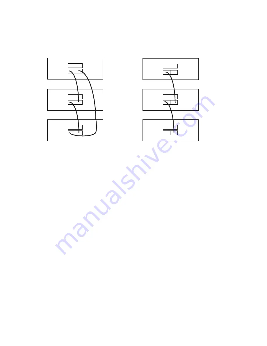
The S55 supports stacking in either a ring or cascade topology. Dell Force10 recommends the ring 
topology when stacking S55 switches, to provide redundant connectivity. 

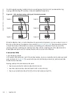
Figure 4-1.  S55 stacking topology with 2-port 12G stacking module

While the diagram shows A-to-B connections, the ports are bi-directional, so you can connect A-to-A or 
B-to-B, as shown below in examples of two-switch (

Figure 4-2

 or 

Figure 4-3

). Rack-mount the switches 

or insert them into a cabinet before you make your stacking port connections. Insert one end of the 
stacking cable into a stacking port, and insert the other end into a stacking port of the adjacent switch. 
Hand-tighten all captive screws to ensure that the cable is secure in the connector. 

Connect two S55s

2-port 12G stacking modules

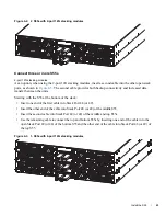
As an option, when using the 2-port 12G stacking modules, insert a second cable into the other open stack 
ports, as shown in 

Figure 4-2

. The second cable provides both backup connectivity and increased data 

transfer between the units.

Starting with the S55 at the bottom of the stack:

Insert one end of the first cable into Stack Port 48 (or 49). 

Insert the other end of the cable into Stack Port 48 (or 49) of the top. 

Insert a second cable into Stack Port 49 (or 48) of the bottom and top S55s. 

Switch 1

Switch 2

Switch 3

Switch 1

Switch 2

Switch 3

48

49

48

49

48

49

48

49

48

49

48

49

Содержание Force10 S55

Страница 1: ...Installing the S55 System ...

Страница 2: ...AMD Sempron are trademarks of Advanced Micro Devices Inc Microsoft Windows Windows Server MS DOS and Windows Vista are either trademarks or registered trademarks of Microsoft Corporation in the United States and or other countries Red Hat Enterprise Linux and Enterprise Linux are registered trademarks of Red Hat Inc in the United States and or other countries Novell is a registered trademark and S...

Страница 3: ...ns and airflow 14 Power 14 Storing components 15 4 Install the S55 Install the S55 chassis in a rack or cabinet 17 Attach mounting brackets 17 Install chassis into rack or cabinet 18 Attach ground cable 19 Insert optional modules 20 Install the SFP and SFP optics 21 Connect stacking ports optional 21 Connect two S55s 22 Connect three or more S55s 23 Supply power and power up the system 24 Power up...

Страница 4: ...he USB B console port 34 8 S55 Specifications Chassis Physical Design 37 Environmental Parameters 37 AC Power Requirements 37 DC Power Requirements 38 IEEE Standards 38 Agency Compliance 38 NEBS Network Equipment Building Systems Compliance 38 Safety Standards and Compliance Agency Certifications 41 Electromagnetic Compatibility EMC 41 Product Recycling and Disposal 42 9 Technical Support The iSup...

Страница 5: ...is guide before installing and powering up this equipment This equipment contains two power cords Disconnect both power cords before servicing WARNING This equipment contains optical transceivers which comply with the limits of Class 1 laser radiation WARNING Visible and invisible laser radiation may be emitted from the aperture of the optical transceiver ports when no cable is connected Avoid exp...

Страница 6: ...e following documents FTOS Configuration Guide for the S55 system FTOS Command Reference for the S55 system FTOS Release Notes for the S55 system NOTE For the most recent documentation and software please visit iSupport registration for access to some sections is required https www force10networks com CSPortal20 Main SupportMain aspx ...

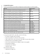
Страница 7: ...slots As shown in Figure 2 2 the S55 s I O Input Output side contains the 44 Ethernet ports the SFP ports the management ports and the displays for alarms and stacking identification Figure 2 1 The S55 PSU side Figure 2 2 The S55 I O NOTE The Ethernet ports are labeled 0 43 When cabling these ports be sure not to interfere with the airflow from the small vent holes above and below the ports Fan Po...

Страница 8: ...I O panel to utility panel S55T AC 44 port 10 100 1000 Base T with 4 SFP ports and 2 expansion module slots 1 DC power supply and 2 fan units with airflow from I O panel to utility panel S55T DC 44 port 10 100 1000 Base T with 4 SFP ports and 2 expansion module slots 1 AC power supply and 2 fan units with airflow from utility panel to I O panel S55T AC R 44 port 10 100 1000 Base T with 4 SFP ports...

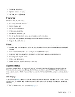
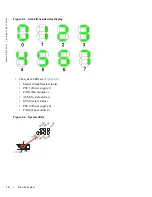
Страница 9: ...45 ports Four fixed ports supporting 100 1000 Base T or 1000 Base X using auto media detection Console port for system access USB A port for storage USB B port for system connectivity and access System status S55 status information is viewed in several ways including physical displays and boot menu options Status information is also seen through the CLI show commands and with SNMP traps For detail...

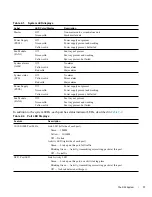
Страница 10: ...The system LEDs are Figure 2 4 Master Stack Master status PSU1 Power supply 1 FAN1 Fan module 1 ALM System alarms SYS System status PSU0 Power supply 0 FAN0 Fan module 0 Figure 2 4 System LEDs USB A Port Stack ID Alarm LEDs Grounding 10 100 1000 Management Port M a s t e r P S U 1 F A N 1 ALM SYS PSU0 FAN0 ...

Страница 11: ...Off Yellow solid Red solid No alarm Minor alarm Major alarm Power Supply PSU0 Off Green solid Yellow solid Power supply not present Power supply present and working Power supply present but failed Fan Module FAN0 Off Green solid Yellow solid Fan tray not present Fan tray present and working Fan tray present but failed Table 2 2 Port LED Displays Feature Description 10 100 1000 Port LEDs Link LED l...

Страница 12: ...12 The S55 System w w w d e l l c o m s u p p o r t d e l l c o m ...

Страница 13: ...is one in which access can only be gained by service personnel through the use of a special tool lock key or other means of security and access is controlled by the authority responsible for the location Make sure that the area where you install your S55 chassis meets the following safety requirements Near an adequate power source Connect the system to the appropriate branch circuit protection as ...

Страница 14: ...d Normal airflows in a single chassis Normal is airflow from I O panel to power supply Reversed is airflow from power supply to I O panel For proper ventilation position the S55 chassis in an equipment rack or cabinet with a minimum of five inches 12 7 cm of clearance around exhaust vents When two S55 systems are installed near each other position the two chassis at least 5 inches 12 7 cm apart to...

Страница 15: ... components immediately Dell Force10 recommends that you properly store the S55 and all optional components until you are ready to install them WARNING Electrostatic discharge ESD damage can occur when components are mishandled Always wear an ESD preventive wrist or heel ground strap when handling the S55 and its accessories After you remove the original packaging place the S55 and its components ...

Страница 16: ...16 Site Preparations w w w d e l l c o m s u p p o r t d e l l c o m ...

Страница 17: ...the system WARNING Always wear an ESD preventive wrist or heel ground strap when handling the S55 and its components As with all electrical devices of this type take all the necessary safety precautions to prevent injury when installing this system Electrostatic discharge ESD damage can occur if components are mishandled Install the S55 chassis in a rack or cabinet Attach mounting brackets The S55...

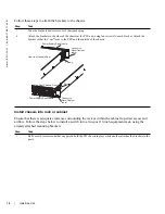
Страница 18: ...y attached mounting brackets Step Task 1 Take the brackets and screws out of their packaging 2 Attach the brackets to the sides of the chassis at the PSU end using four screws for each bracket Attach the bracket so that the ear faces to the PSU and the outside of the chassis Step Task 1 Dell Force10 recommends that one person hold the S55 chassis in place while another attaches the brackets to the...

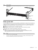
Страница 19: ... connect the ground cable to the chassis NOTE Coat the one hole lug with an anti oxidant compound prior to crimping Bring any un plated mating surfaces to a shiny finish and coat with an anti oxidant prior to mating Plated mating surfaces must be clean and free from contamination 2 Attach the bracket ears to the rack or cabinet posts using two screws for each bracket Ensure the screws are tightene...

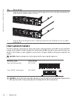
Страница 20: ... into the lower optional module slot WARNING Electrostatic discharge ESD damage can occur if components are mishandled Always wear an ESD preventive wrist or heel ground strap when handling the S55 and its components 3 Attach the one hole lug to the chassis as shown using the supplied 10 32 screw with captive internal tooth lock washer The screw should be torqued to 20 in lbs 4 Attach the other en...

Страница 21: ...nnections Insert one end of the stacking cable into a stacking port and insert the other end into a stacking port of the adjacent switch Hand tighten all captive screws to ensure that the cable is secure in the connector Dell Force10 supports stacking connections for up to 12 S55 switches to configure as a unified system CAUTION The S55 system does not stack with other S Series systems You can con...

Страница 22: ...king cable into a stacking port and insert the other end into a stacking port of the adjacent switch Hand tighten all captive screws to ensure that the cable is secure in the connector Connect two S55s 2 port 12G stacking modules As an option when using the 2 port 12G stacking modules insert a second cable into the other open stack ports as shown in Figure 4 2 The second cable provides both backup...

Страница 23: ...ween the units Starting with the S55 at the bottom of the stack Insert one end of the first cable into Stack Port 48 or 49 Insert the other end of the cable into Stack Port 48 or 49 of the middle S55 Insert the second cable into Stack Port 49 or 49 of the middle and top S55s Use the remaining cable to connect the top and bottom S55s by inserting one end of the cable into the open Stack Port 49 or ...

Страница 24: ...ot installed blank panels are installed if redundant power supplies are not installed NOTE A US AC power cable is included in the shipping container for powering up an AC power supply All other power cables must be ordered separately WARNING Electrostatic discharge ESD damage can occur if components are mishandled Always wear an ESD preventive wrist or heel ground strap when handling the S55 and i...

Страница 25: ... and the new units can be already powered up or they can be powered down All units in a stack must run the same version of the operating system If you attempt to attach a unit with a different version of the operating system to an existing stack the CLI will display an error and the unit will not be added until you install compatible software The order in which the units come on line or are added ...

Страница 26: ...he awareness of the new unit If you have a pre configured unit that you want to add to the stack but you want to make sure that the configuration does not override the configuration of the stack it is best to add the unit while it is powered down in order to avoid stack management conflicts You can use the CLI to make stack identification changes on the fly such as renumbering units switch renumbe...

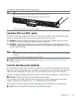
Страница 27: ... If you do not ground your equipment correctly excessive emissions may result Use a qualified electrician to ensure that the power cables meet your local electrical requirements WARNING Electrostatic discharge ESD damage can occur if components are mishandled Always wear an ESD preventive wrist or heel ground strap when handling the S55 and its components Components The following power supply opti...

Страница 28: ...supply and screw terminals that attach to the main power Dell Force10 recommends using a longer cable to ensure sufficient room CAUTION Note is that the power supply is marked 48V Connect the plus sign to the red cable on the 6 8 inch cord the minus sign connects to the black cable BE SURE TO to connect the RED to RETURN and connect the BLACK to 48V Power Supply 0 PSU0 is on the left Power Supply ...

Страница 29: ...wers up as soon as the cables are connected between the power supply and the power source Step Task 1 Disconnect the power cable from the power supply 2 Use the grab handle to slide the unit out of the power supply bay NOTE If the power supply is not going to be replaced attach a blank panel to the power supply slot 3 Using the grab handle on the replacement unit slide it into the power supply bay...

Страница 30: ...30 Power Supplies w w w d e l l c o m s u p p o r t d e l l c o m ...

Страница 31: ...amount of time required between fan replacements Check these environmental factors regularly Any unusual environmental circumstance at the site that causes an increase in temperature and or particulate matter in the air might affect performance for example new equipment installation CAUTION Fans should be checked at six month intervals and replaced as necessary Regularly monitor the speeds of the ...

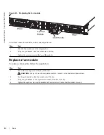
Страница 32: ...slide the module in to the bay 3 Tighten the securing screw at the top of the module Step Task 1 Loosen the securing screw at the top of the unit CAUTION Steps 2 3 must be completed in within 1 minute or the chassis will power down 2 Use the grab handle to slide the module out of the bay 3 Using the grab handle on the replacement module slide it into the bay 4 Tighten the captive screws on the mod...

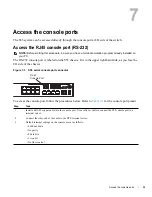
Страница 33: ...he upper right hand side as you face the I O side of the chassis Figure 7 1 S55 serial console port connector To access the console port follow the procedures below Refer to Table 7 1 for the console port pinout Step Task 1 Install an RJ 45 copper cable into the console port Use a rollover cable to connect the S55 console port to a terminal server 2 Connect the other end of the cable to the DTE te...

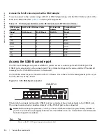
Страница 34: ...O side of the chassis Figure 7 2 S55 USB B port connector When both the console port and the USB B port are connected the system defaults to the USB B port The console connection is considered inactive if the USB B port is also connected NOTE Before starting this procedure be sure you have a terminal emulation program already installed on your PC You will also require appropriate drivers for the U...

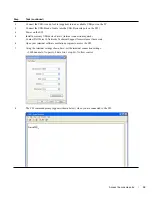
Страница 35: ...evice drivers internet connection required Contact Dell Force10 Networks Technical Support for assistance if necessary 6 Open your terminal software emulation program to access the S55 7 Using the terminal settings shown here set the terminal connection settings 9600 baud rate No parity 8 data bits 1 stop bit No flow control 8 The CLI command prompt appears shown below when you are connected to th...

Страница 36: ...36 Access the console ports w w w d e l l c o m s u p p o r t d e l l c o m ...

Страница 37: ...nts 14 41 pounds approx 6 54 kg Rack clearance required Front 5 inches 12 7 cm Rear 5 inches 12 7 cm Thermal Dissipation 461 BTU hr 135W Power Consumption 115 Watts nominal 135 Watts maximum Parameter Specifications Temperature 32 to 104 F 0 to 40 C 40 to 158 F 40 to 70 C Maximum altitude No performance degradation to 10 000 feet 3 048 meters Relative humidity 10 to 85 non condensing Shock MIL STD...

Страница 38: ...t be used for ports 0 43 The shields must be grounded at both ends Only reverse air flow configurations may be used in a NEBS compliant installation Use only AC supply S55 PWR AC R DC supply S55 PWR DC R and Fan Only S55 FAN R Systems S55 44T AC R and S55 44T DC R Power supplies and fan modules must be fitted with the S55 PWR FLTR kits Fan filters must be replaced on a regular basis This equipment...

Страница 39: ...Operation of this equipment in a residential area is likely to cause harmful interference in which case users will be required to take whatever measures necessary to correct the interference at their own expense Properly shielded and grounded cables and connectors must be used in order to meet FCC emission limits Dell Force10 is not responsible for any radio or television interference caused by us...

Страница 40: ...e10networks com german Tel 49 172 6802630 Email EMEA Central Sales Figure 8 5 Japan VCCI Compliance for Class A Equipment This is Class A product based on the standard of the Voluntary Control Council For Interference by Information Technology Equipment VCCI If this equipment is used in a domestic environment radio disturbance may arise When such trouble occurs the user may be required to take cor...

Страница 41: ...uirements and User s Guide EN 60825 2 Safety of Laser Products Part 2 Safety of Optical Fibre Communication Systems FDA Regulation 21CFR 1040 10 and 1040 11 IEC 60950 1 2nd Ed including all National Deviations and Group Differences Electromagnetic Compatibility EMC Emissions International CISPR 22 2006 Class A Australia New Zealand AS NZS CISPR 22 2006 Class A Canada ICES 003 Issue 4 Class A Europ...

Страница 42: ...e of IT and Telecommunications Products Dell Force10 switches are labeled in accordance with European Directive 2002 96 EC concerning waste electrical and electronic equipment WEEE The Directive determines the framework for the return and recycling of used appliances as applicable throughout the European Union This label is applied to various products to indicate that the product is not to be thro...

Страница 43: ...crews that connect the top to the body There are three screws evenly spaced across the rear and three screws evenly spaced along each side 2 Slide the top backwards until its front flange slides free of the faceplate then lift it off 3 Remove the small screw at the top of the SD card slot 4 Gently push the SD card to release it from the slot 5 Remove the card Battery replacement The lithium batter...

Страница 44: ...d separately and recycled at end of life The label on the battery may also include a chemical symbol for the metal concerned in the battery Pb for lead Hg for mercury and Cd for cadmium Users of batteries and accumulators must not dispose of batteries and accumulators as unsorted municipal waste but use the collection framework available to customers for the return recycling and treatment of batte...

Страница 45: ...s access to software upgrades and patches and open and manage your Technical Assistance Center TAC cases Dell Force10 iSupport provides integrated secure access to these services Accessing iSupport services The URL for iSupport is http www force10networks com support You must have a userid and password to access iSupport services If you do not have one you can request one at the website On the Del...

Страница 46: ... command where unit is the stack ID of the member unit that experienced the failure This report is included as a section in the output of show tech support Console captures showing the error messages Console captures showing the troubleshooting steps taken Saved messages to a syslog server if one is used Managing Your Case Log in to iSupport and select the Service Request tab to view all open case...

Страница 47: ...ax number and e mail address Shipping address for the replacement component including a contact name phone number and e mail address A description of the failure including log messages This generally includes Output from the show tech support non paged command This report is very long so the storage buffer in your terminal program should be set high Output from the show logging eventlog unit comma...

Страница 48: ...48 Technical Support w w w d e l l c o m s u p p o r t d e l l c o m ...

Страница 49: ......

Страница 50: ...w w w d ell com support dell com Printed in the U S A ...

Отзывы: