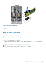
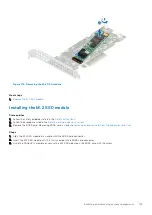
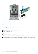
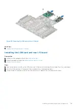

Figure 133. Installing the internal USB card
Next steps
1.
Install the expansion card risers
.
2. Follow the procedure listed in
After working inside your system
.
3. While booting, press F2 to enter
System Setup
and verify that the system detects the USB memory key.
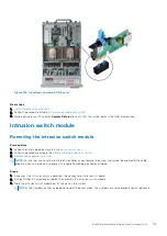
Intrusion switch module
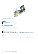
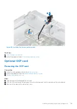
Removing the intrusion switch module
Prerequisites
1. Follow the safety guidelines listed in the
.
2. Follow the procedure listed in the
Before working inside your system
3.
Remove the expansion card riser
.
NOTE:
Ensure that you note the routing of the cables as you remove them from the system board. Route the cable
properly when you replace it to prevent the cable from being pinched or crimped
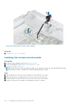
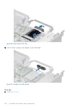
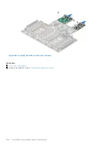
Steps
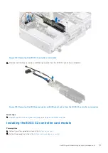
1. Disconnect the intrusion switch cable from the connector on the rear I/O board.
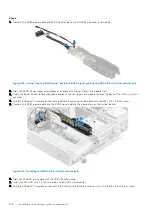
2. Using a Phillips #2 screwdriver, loosen the screw on the intrusion switch module.
3. Slide the intrusion switch module out of the slot on the system.
NOTE:
The numbers on the image do not depict the exact steps. The numbers are for representation of sequence.
Installing and removing system components
153
Содержание E68S
Страница 19: ...Figure 14 Service information System overview 19 ...
Страница 28: ...Cable routing Figure 18 12x 3 5 inch Figure 19 8 x 3 5 inch 28 Installing and removing system components ...
Страница 30: ...Figure 22 24 x 2 5 inch with NVMe Figure 23 16 x 2 5 inch 30 Installing and removing system components ...
Страница 31: ...Figure 24 8 x 2 5 inch with NVMe Figure 25 8 x 2 5 inch with NVMe Installing and removing system components 31 ...


