background image

Move the jumper on the system board jumper from pins 2 and 4 to pins 4 and 6.

Install the system cover.

10  Reconnect the system to its electrical outlet and turn on the system, including any attached peripherals.
11  Assign a new system and/or setup password.

Related links

Removing the system cover
Installing the system cover

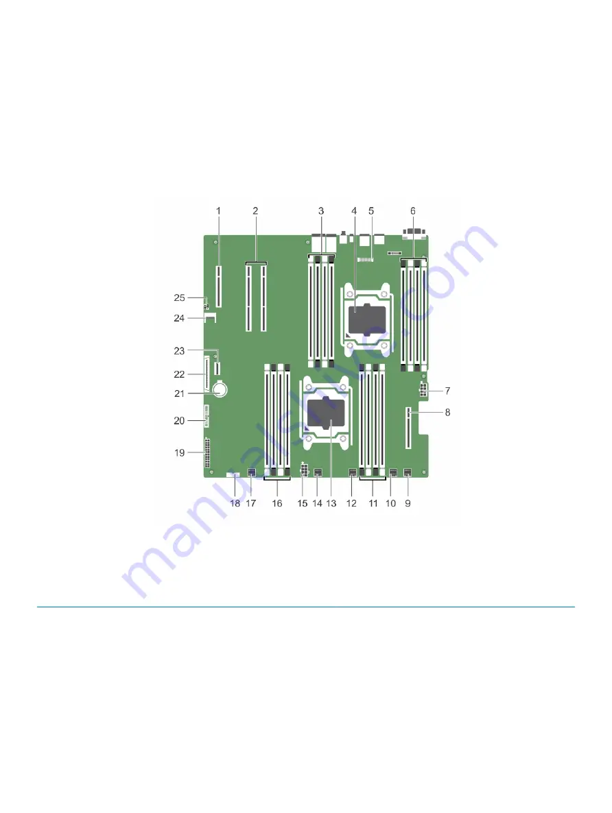
System board connectors

Figure 80. System board connectors and jumpers

Table 38. System board connectors and jumpers

Item

Connector

Description

1

PCIE _G3_X8 (PCH)

PCIE Slot 3 (x4)

2

PCIE_G3_X16 (CPU1)

PCIe Slot 2 and PCIe Slot 1 (PCIe Slot is closer to the CPU2 
socket)

3

B1, B5, B2, B6

DIMMS for CPU2 channels 0&1

4

CPU2

Processor socket 2

5

J-AMEA

Remote management port card connector

6

B8, B4, B7, B3

DIMMS for CPU2 channels 2&3

Jumpers and connectors 

151

Содержание DSS 2500

Страница 1: ...Dell DSS 2500 Owner s Manual Regulatory Model E29S Series Regulatory Type E29S002 ...

Страница 2: ...age to hardware or loss of data and tells you how to avoid the problem WARNING A WARNING indicates a potential for property damage personal injury or death 2016 2018 Dell Inc or its subsidiaries All rights reserved Dell EMC and other trademarks are trademarks of Dell Inc or its subsidiaries Other trademarks may be trademarks of their respective owners 2018 11 Rev A02 ...

Страница 3: ...s dimensions 19 Chassis weight 19 Processor specifications 20 PSU specifications 20 System battery specifications 20 Storage controller specifications 20 Expansion bus specifications 20 Memory specifications 21 Drive specifications 21 Ports and connectors specifications 21 USB ports 21 NIC ports 21 VGA port 22 Remote management port 22 Serial connector 22 Internal SAS connector 22 Video specificat...

Страница 4: ...ule installation guidelines 63 Mode specific guidelines 63 Sample memory configurations 64 Removing memory modules 66 Installing memory modules 67 Hard drives 68 Removing a hot swappable hard drive carrier 69 Installing a hot swappable hard drive carrier 70 Removing a 3 5 inch hard drive blank 71 Installing a 3 5 inch hard drive blank 71 Installing a 2 5 inch hard drive into a 3 5 inch hard drive ...

Страница 5: ...e internal PERC riser 101 Removing an expansion card from the dual riser module 103 Installing an expansion card into the dual riser module 105 Remote management port card optional 107 Removing the optional remote management port card 108 Installing the optional remote management port card 109 Processors and heat sinks 110 Removing a heat sink 111 Removing a processor 112 Installing a processor 11...

Страница 6: ...rst for you and your system 153 Troubleshooting system startup failure 153 Troubleshooting external connections 153 Troubleshooting the video subsystem 154 Troubleshooting a USB device 154 Troubleshooting a serial input and output device 154 Troubleshooting a NIC 155 Troubleshooting a wet system 155 Troubleshooting a damaged system 156 Troubleshooting the system battery 157 Troubleshooting power s...

Страница 7: ...oduct family processor 12 x 3 5 inch or 2 5 inch hot swappable hard drives SSDs with redundant power supply unit PSU 16 DIMMs supporting up to 512 GB of memory Two AC redundant PSUs Topics Supported configurations for the Dell DSS 2500 system Front panel Back panel features Diagnostic indicators on the front panel Locating service tag of your system 1 Dell DSS 2500 system overview 7 ...

Страница 8: ...Supported configurations for the Dell DSS 2500 system Figure 1 Supported configurations for the DSS 2500 system 8 Dell DSS 2500 system overview ...

Страница 9: ...status For more information see the Diagnostic indicators section 2 Power button Indicates if the system is turned on or off Press the power button to manually turn on or off the system NOTE Press the power button to gracefully shut down an ACPI compliant operating system 3 Information tag The Information Tag is a slide out label panel that contains system information such as Service Tag NIC MAC a...

Страница 10: ... button or connector Icon Description 1 Serial port Enables you to connect a serial device to the system For more information see the Technical specifications section 2 Retention screw Use the retention screw to secure the system cover to the chassis 3 BMC port optional Use the dedicated management port for the BMC ports card 4 PCIe expansion card retainer Use the PCIe expansion card retainer to l...

Страница 11: ... 11 USB port Use the USB 2 0 port to connect USB devices to the system These ports are 4 pin USB 2 0 compliant 12 Video port Use the video VGA port to connect a display to the system For more information about the supported video VGA port see the Technical specifications section Related links Serial connector PSU specifications USB ports NIC ports VGA port System with dual riser module Figure 4 Ba...

Страница 12: ...e supported Ethernet ports see the Technical specifications section 8 System identification button Press the system ID button To locate a particular system within a rack To turn the system ID on or off To reset BMC press and hold the button for more than 15 seconds NOTE To reset BMC using system ID ensure that the system ID button is enabled in the BMC setup NOTE If the system stops responding dur...

Страница 13: ...he system is in good health None required The indicator blinks amber When the system is turned on When the system is in standby If any error condition exists For example a failed fan power supply unit PSU or a hard drive Check the System Event Log or system messages for the specific issue For more information about error messages see the Dell Event and Error Messages Reference Guide at Dell com op...

Страница 14: ... on the right side does not turn on Table 5 Hard drive indicator codes Drive status indicator pattern Condition Flashes green twice per second Identifying drive or preparing for removal Off Drive ready for insertion or removal NOTE The drive status indicator remains off until all hard drives are initialized after the system is turned on Drives are not ready for insertion or removal during this tim...

Страница 15: ...and activity indicators are off The NIC is not connected to the network B Link indicator is green The NIC is connected to a valid network at its maximum port speed 1 Gbps or 10 Gbps C Link indicator is amber The NIC is connected to a valid network at less than its maximum port speed D Activity indicator is flashing green Network data is being sent or received Redundant power supply unit indicator ...

Страница 16: ...N For AC PSUs use only PSUs with the Extended Power Performance EPP label on the back NOTE Ensure that both the PSUs are of the same capacity NOTE Mixing PSUs from previous generations of Dell servers can result in a PSU mismatch condition or failure to turn the system on D Flashing amber Indicates a problem with the PSU CAUTION When correcting a PSU mismatch replace only the PSU with the flashing...

Страница 17: ...our system Your system is identified by a unique Express Service Code and Service Tag number The Express Service Code is and Service Tag are found on the front of the system by pulling out the information tag Alternatively the information may be on a sticker on the chassis of the system This information is used by Dell to route support calls to the appropriate personnel Dell DSS 2500 system overvi...

Страница 18: ...perating system see the operating system documentation Dell com operatingsystemmanuals For understanding Remote Access Controller Admin RACADM subcommands and supported RACADM interfaces see the RACADM Command Line Reference Guide for iDRAC Dell com poweredgemanuals For information about updating drivers and firmware see the Methods to download firmware and drivers section in this document Dell co...

Страница 19: ... Dimensions of the DSS 2500 system System X Xa Y Za Zb Z 12 x 3 5 inch or 2 5 inch hard drive systems 482 4 mm 18 9 inch 434 0 mm 17 08 inch 86 8 mm 3 41 inch 20 1 mm 0 79 inch 646 7 mm 25 46 inch 666 8 mm 26 25 inch Chassis weight Table 10 Chassis weight System Maximum weight 12 x 3 5 inch hard drive or 2 5 inch hard drive SSD systems 28 2 kg 62 17 lb 3 Technical specifications 19 ...

Страница 20: ...se to phase voltage not exceeding 230 V System battery specifications The DSS 2500 system supports CR 2032 3 0 V lithium coin cell system battery Storage controller specifications The DSS 2500 system supports PERC H330 PERC H730 and PERC H730P storage controllers Expansion bus specifications The Dell DSS 2500 system supports PCI express PCIe generation 3 expansion cards which can be installed on t...

Страница 21: ...ssors Drive specifications The DSS 2500 system supports Up to twelve 3 5 inch or 2 5 inch with 3 5 inch drive carrier adapters hot swappable SAS SATA or Nearline SAS hard drives Up to twelve 3 5 inch or 2 5 inch with hybrid drive carriers hot swappable SATA SSDs Up to two 2 5 inch internal cabled SATA hard drives NOTE These internal drives are used only for the operating system They will not be co...

Страница 22: ...cifications The DSS 2500 system supports Integrated Matrox G200 graphics card with 16 MB capacity Environmental specifications NOTE For additional information about environmental measurements for specific system configurations see Dell com environmental_datasheets Table 16 Temperature specifications Temperature Specifications Storage 40 C to 65 C 40 F to 149 F Continuous operation for altitude les...

Страница 23: ...e 20 Maximum altitude specifications Maximum altitude Specifications Operating 3048 m 10 000 ft Storage 12 000 m 39 370 ft Table 21 Operating temperature de rating specifications Operating temperature de rating Specifications Up to 35 C 95 F Maximum temperature is reduced by 1 C 300 m 1 F 547 ft above 950 m 3 117 ft 35 C to 40 C 95 F to 104 F Maximum temperature is reduced by 1 C 175 m 1 F 319 ft ...

Страница 24: ... 60 relative humidity NOTE This condition applies to data center and non data center environments Table 23 Gaseous contamination specifications Gaseous contamination Specifications Copper coupon corrosion rate 300 Å month per Class G1 as defined by ANSI ISA71 04 1985 Silver coupon corrosion rate 200 Å month as defined by AHSRAE TC9 9 NOTE Maximum corrosive contaminant levels measured at 50 relativ...

Страница 25: ... annual operating hours For temperatures between 40 C and 45 C de rate maximum allowable temperature by 1 C per 125 m above 950 m 1 F per 228 ft NOTE When operating in the expanded temperature range system performance may be impacted NOTE When operating in the expanded temperature range ambient temperature warnings maybe reported in the System Event Log Technical specifications 25 ...

Страница 26: ...grated Dell Remote Access Controller User s Guide at Dell com idracmanuals Dell Deployment Toolkit See Dell Deployment Toolkit User s Guide at Dell com openmanagemanuals Remote Access Controller Admin RACADM See RACADM Command Line Interface Reference Guide and Integrated Dell Remote Access Controller User s Guide at Dell com idracmanuals Remote Services that include Web Services Management WS Man...

Страница 27: ... com operatingsystemmanuals Dell certified VMware ESXi Dell com virtualizationsolutions Supported operating systems on Dell DSS systems Dell com ossupport Methods to download firmware and drivers You can download the firmware and drivers by using any of the following methods Table 26 Firmware and drivers Methods Location From the Dell Support site Global Technical Support Using BMC Dell com idracm...

Страница 28: ...4 Download the drivers to a USB drive CD or DVD 28 Initial system setup and configuration ...

Страница 29: ...er Preboot Execution Environment PXE Related links System Setup Boot Manager PXE boot System Setup By using the System Setup screen you can configure the BIOS settings BMCsettings and device settings of your system NOTE Help text for the selected field is displayed in the graphical browser by default To view the help text in the text browser press F1 You can access system setup by using two method...

Страница 30: ...ttings iDRAC Settings Enables you to configure BMC settings The iDRAC settings utility is an interface to set up and configure the BMC parameters by using UEFI You can enable or disable various BMC parameters by using the iDRAC settings utility For more information about this utility see Integrated Dell Remote Access Controller 8 User s Guide at Dell com idracmanuals Device Settings Enables you to...

Страница 31: ...plained as follows Option Description System Information Specifies information about the system such as the system model name BIOS version and Service Tag Memory Settings Specifies information and options related to the installed memory Processor Settings Specifies information and options related to the processor such as speed and cache size SATA Settings Specifies options to enable or disable the...

Страница 32: ... F2 immediately after you see the following message F2 System Setup NOTE If your operating system begins to load before you press F2 wait for the system to finish booting and then restart your system and try again 3 On the System Setup Main Menu screen click System BIOS 4 On the System BIOS screen click Boot Settings Related links Boot Settings Boot Settings details Choosing the system boot mode C...

Страница 33: ...mode is an enhanced 64 bit boot interface If you have configured your system to boot to UEFI mode it replaces the system BIOS 1 From the System Setup Main Menu click Boot Settings and select Boot Mode 2 Select the boot mode you want the system to boot into CAUTION Switching the boot mode may prevent the system from booting if the operating system is not installed in the same boot mode 3 After the ...

Страница 34: ...Turn on or restart your system 2 Press F2 immediately after you see the following message F2 System Setup NOTE If your operating system begins to load before you press F2 wait for the system to finish booting and then restart your system and try again 3 On the System Setup Main Menu screen click System BIOS 4 On the System BIOS screen click Network Settings Related links Network Settings Network S...

Страница 35: ...screen click System BIOS 4 On the System BIOS screen click Network Settings 5 On the Network Settings screen click UEFI iSCSI Settings Related link UEFI iSCSI Settings UEFI iSCSI Settings details The UEFI ISCSI Settings screen details are explained as follows Option Description ISCSI Initiator Name Specifies the name of the iSCSI initiator iqn format ISCSI Device n n 1 to 4 Enables or disables the...

Страница 36: ... The TPM Security option is set to Off by default You can only modify the TPM Status TPM Activation and Intel TXT fields if the TPM Status field is set to either On with Pre boot Measurements or On without Pre boot Measurements TPM Information Changes the operational state of the TPM This option is set to No Change by default TPM Status Specifies the TPM status TPM Command CAUTION Clearing the TPM...

Страница 37: ...g message F2 System Setup NOTE If your operating system begins to load before you press F2 wait for the system to finish booting and then restart your system and try again 3 On the System Setup Main Menu screen click System BIOS 4 On the System BIOS screen click System Security 5 On the System Security screen click Secure Boot Custom Policy Settings Secure Boot Custom Policy Settings details The S...

Страница 38: ...ure your system About this task If you have assigned a setup password the system accepts your setup password as an alternate system password Steps 1 Turn on or reboot your system 2 Type the system password and press Enter Next step When Password Status is set to Locked type the system password and press Enter when prompted at reboot NOTE If an incorrect system password is typed the system displays...

Страница 39: ... Halted Must power down Even after you turn off and restart the system the error message is displayed until the correct password is typed The following options are exceptions If System Password is not set to Enabled and is not locked through the Password Status option you can assign a system password For more information see the System Security Settings screen section You cannot disable or change ...

Страница 40: ...D firmware UEFI Compliance Version Specifies the UEFI compliance level of the system firmware Related links System Information System Information details Viewing System Information Memory Settings You can use the Memory Settings screen to view all the memory settings and enable or disable specific memory functions such as memory testing and node interleaving Related links Memory Settings details S...

Страница 41: ...ting Mode option can have different default and available options based on the memory configuration of your system Node Interleaving Specifies if the Non Uniform Memory Architecture NUMA is supported If this field is set to Enabled memory interleaving is supported if a symmetric memory configuration is installed If the field is set to Disabled the system supports NUMA asymmetric memory configurati...

Страница 42: ...e ATC for devices to cache the DMA transactions This option provides an interface between CPU and DMA Memory Management to a chipset s Address Translation and Protection Table to translate DMA addresses to host addresses This option is set to Enabled by default Adjacent Cache Line Prefetch Optimizes the system for applications that need high utilization of sequential memory access This option is s...

Страница 43: ...mily Model Stepping Specifies the family model and stepping of the processor as defined by Intel Brand Specifies the brand name Level 2 Cache Specifies the total L2 cache Level 3 Cache Specifies the total L3 cache Number of Cores Specifies the number of cores per processor Related links Processor Settings Viewing Processor Settings SATA Settings You can use the SATA Settings screen to view the SAT...

Страница 44: ...Type Specifies the type of drive attached to the SATA port Capacity Specifies the total capacity of the hard drive This field is undefined for removable media devices such as optical drives Port B Sets the drive type of the selected device For Embedded SATA settings in ATA mode set this field to Auto to enable BIOS support Set it to OFF to turn off BIOS support For AHCI or RAID mode BIOS support i...

Страница 45: ...grated Network Card 1 Enables or disables the Embedded NIC1 and NIC2 options If set to Disabled the NIC may still be available for shared network access by the embedded management controller The embedded NIC1 and NIC2 options are only available on systems that do not have Network Daughter Cards NDCs The Embedded NIC1 and NIC2 option is mutually exclusive with the Integrated Network Card 1 option C...

Страница 46: ...stem BIOS Viewing Serial Communication Viewing Serial Communication To view the Serial Communication screen perform the following steps 1 Turn on or restart your system 2 Press F2 immediately after you see the following message F2 System Setup NOTE If your operating system begins to load before you press F2 wait for the system to finish booting and then restart your system and try again 3 On the S...

Страница 47: ...he attempt fails and the value must not be changed This option is set to 115200 by default Remote Terminal Type Sets the remote console terminal type This option is set to VT 100 VT 220 by default Redirection After Boot Enables or disables the BIOS console redirection when the operating system is loaded This option is set to Enabled by default Related links Serial Communication Viewing Serial Comm...

Страница 48: ...by the OS DBPM and the System DBPM DAPC This option is set to Disabled by default Memory Patrol Scrub Sets the memory patrol scrub frequency This option is set to Standard by default Memory Refresh Rate Sets the memory refresh rate to either 1x or 2x This option is set to 1x by default Uncore Frequency Enables you to select the Processor Uncore Frequency option Dynamic mode enables the processor t...

Страница 49: ...rd NumLock Enables you to set whether the system boots with the NumLock enabled or disabled This option is set to On by default NOTE This option does not apply to 84 key keyboards F1 F2 Prompt on Error Enables or disables the F1 F2 prompt on error This option is set to Enabled by default The F1 F2 prompt also includes keyboard errors Load Legacy Video Option ROM Enables you to determine whether th...

Страница 50: ...User s Guide at Dell com idracmanuals Related links Device Settings System BIOS Entering the iDRAC Settings utility Changing the thermal settings Entering the iDRAC Settings utility 1 Turn on or restart the managed system 2 Press F2 during Power on Self test POST 3 On the System Setup Main Menu page click iDRAC Settings The iDRAC Settings screen is displayed Related link iDRAC Settings utility Cha...

Страница 51: ...Boot Manager main menu Boot Manager main menu Menu item Description Continue Normal Boot The system attempts to boot to devices starting with the first item in the boot order If the boot attempt fails the system continues with the next item in the boot order until the boot is successful or no more boot options are found One shot Boot Menu Enables you to access boot menu where you can select a one ...

Страница 52: ...n the boot mode selected you might have BIOS or UEFI Update File Explorer Related link Boot Manager PXE boot You can use the Preboot Execution Environment PXE option to boot and configure the networked systems remotely NOTE To access the PXE boot option boot the system and then press F12 The system scans and displays the active networked systems 52 Pre operating system management applications ...

Страница 53: ...moving the system cover while the system is powered on may expose you to a risk of electric shock CAUTION Do not operate the system without the cover for a duration exceeding five minutes CAUTION Many repairs may only be done by a certified service technician You should only perform troubleshooting and simple repairs as authorized in your product documentation or as directed by the online or telep...

Страница 54: ...g any attached peripherals Related links Safety instructions Installing the system cover Recommended tools You need the following tools to perform the removal and installation procedures Phillips 1 screwdriver Phillips 2 screwdriver T15 Torx screwdriver Plastic scribe Wrist grounding strap System cover The system cover protects the components inside the system and helps in maintaining air flow ins...

Страница 55: ...r Prerequisite CAUTION Many repairs may only be done by a certified service technician You should only perform troubleshooting and simple repairs as authorized in your product documentation or as directed by the online or telephone service and support team Damage due to servicing that is not authorized by Dell is not covered by your warranty Read and follow the safety instructions that are shipped...

Страница 56: ...Figure 10 Installing the system cover 1 system cover 2 retention screw Related links Safety instructions Removing the system cover 56 Installing and removing system components ...

Страница 57: ...nside the system with internal PERC riser 1 hard drive backplane 2 cooling fan 6 3 internal hard drive module 4 power interposer board 5 power supply 6 processor 2 7 internal PERC riser Installing and removing system components 57 ...

Страница 58: ...r supply 6 dual riser module 7 processor 2 8 internal PERC riser Cooling shroud The cooling shroud aerodynamically directs the airflow across the entire system The airflow passes through all the critical parts of the system where the vacuum pulls air across the entire surface area of the heat sink thus allowing increased cooling 58 Installing and removing system components ...

Страница 59: ...d in the Safety instructions section 2 Follow the procedure listed in the Before working inside your system section 3 If connected disconnect the cables from expansion card s NOTE If required close the expansion card latch on the cooling shroud to release the full length card 4 If installed remove the expansion card riser CAUTION Never operate your system with the air shroud removed The system may...

Страница 60: ... inside your system Safety instructions Installing the cooling shroud Prerequisites CAUTION Many repairs may only be done by a certified service technician You should only perform troubleshooting and simple repairs as authorized in your product documentation or as directed by the online or telephone service and support team Damage due to servicing that is not authorized by Dell is not covered by y...

Страница 61: ... slot 2 3 cooling shroud alignment pin 2 Figure 16 Installing the cooling shroud 140 W processor 1 cooling shroud Next steps 1 Install the optional PCIe expansion card riser 2 If disconnected reconnect the cables to the expansion card s 3 If required open the expansion card latch on the cooling shroud to support the full length expansion card 4 Follow the procedure listed in the After working insi...

Страница 62: ...tem profile selected for example Performance Optimized Custom or Dense Configuration Optimized Maximum supported DIMM frequency of the processors Your system contains 16 memory sockets split into four sets of four sockets DIMMs in sockets A1 to A8 are assigned to processor 1 and DIMMs in sockets B1 to B8 are assigned to processor 2 Each 4 socket set is organized into two channels In each channel o...

Страница 63: ...rs first and then all the sockets with black release levers When mixing memory modules with different capacities populate the sockets with memory modules with highest capacity first For example if you want to mix 4 GB and 8 GB DIMMs populate 8 GB DIMMs in the sockets with white release levers and 4 GB DIMMs in the sockets with black release levers In a dual processor configuration the memory confi...

Страница 64: ...e errors are detected on a rank the data from this rank is copied to the spare rank and the failed rank is disabled With memory sparing enabled the system memory available to the operating system is reduced by one rank per channel For example in a dual processor configuration with sixteen 4 GB single rank memory modules the available system memory is 3 4 ranks channel 16 memory modules 4 GB 48 GB ...

Страница 65: ...3 A4 A5 A6 A7 A8 32 4 2R x4 2400 MT s A1 A2 A3 A4 192 32 6 2R x4 2400 MT s A1 A2 A3 A4 A5 A6 256 32 8 2R x4 2400 MT s A1 A2 A3 A4 A5 A6 A7 A8 Table 30 Memory configurations two processors System Capacity in GB DIMM Size in GB Number of DIMMs DIMM Rank Organization and Frequency DIMM Slot Population 16 8 2 1R x8 2400 MT s A1 B1 32 8 4 1R x8 2400 MT s A1 A2 B1 B2 16 2 2R x8 2400 MT s A1 B1 48 8 6 1R...

Страница 66: ... Removing memory modules Prerequisites 1 Remove the cooling shroud NOTE If open close the expansion card latch on the cooling shroud to release the full length card 2 If connected disconnect the cables from expansion card s 3 If installed remove the expansion card riser WARNING The memory modules are hot to touch for some time after the system has been powered down Allow the memory modules to cool...

Страница 67: ...ing shroud to support the full length expansion card Related links Safety instructions System Setup Before working inside your system Removing the cooling shroud Removing the dual riser module optional Removing the internal PERC riser Installing memory modules Installing the internal PERC riser Installing the dual riser module optional Installing the cooling shroud After working inside your system...

Страница 68: ... Figure 19 Installing the memory module 1 memory module 2 alignment key 3 memory module socket ejector 2 Related links Safety instructions System Setup Before working inside your system Removing the cooling shroud Removing the internal PERC riser Installing the internal PERC riser Installing the cooling shroud After working inside your system Using system diagnostics Hard drives Your system suppor...

Страница 69: ...ized by Dell is not covered by your warranty Read and follow the safety instructions that came with the product 1 Follow the safety guidelines listed in the Safety instructions section 2 Using the management software prepare the hard drive for removal For more information see the documentation for the storage controller If the hard drive is online the green activity fault indicator flashes when th...

Страница 70: ...ier can damage the partially installed carrier s shield spring and make it unusable CAUTION To prevent data loss ensure that your operating system supports hot swap drive installation See the documentation supplied with your operating system CAUTION When a replacement hot swappable drive is installed and the system is powered on the drive automatically begins to rebuild Ensure that the replacement...

Страница 71: ...came with the product CAUTION To maintain proper system cooling all empty hard drive slots must have hard drive blanks installed 1 Follow the safety guidelines listed in the Safety instructions section Step Press the release button and slide the blank out of the hard drive slot Figure 22 Removing a 3 5 inch hard drive blank 1 hard drive blank 2 release button Related links Safety instructions Inst...

Страница 72: ...service and support team Damage due to servicing that is not authorized by Dell is not covered by your warranty Read and follow the safety instructions that are shipped with your product 1 Follow the safety guidelines listed in the Safety instructions section 2 Keep the Phillips 2 screwdriver ready 3 Remove a 3 5 inch hot swappable hard drive adapter from a 3 5 inch hot swappable hard drive carrie...

Страница 73: ...pairs as authorized in your product documentation or as directed by the online or telephone service and support team Damage due to servicing that is not authorized by Dell is not covered by your warranty Read and follow the safety instructions that came with the product 1 Follow the safety guidelines listed in the Safety instructions section 2 Keep the Phillips 2 screwdriver ready 3 Remove the 3 5...

Страница 74: ...d drive carrier Prerequisites 1 Follow the safety guidelines listed in the Safety instructions section 2 Keep the Phillips 2 screwdriver ready 3 Remove the 3 5 inch hot swappable hard drive carrier from the system Steps 1 Remove the screws from the rails on the 3 5 inch hot swappable hard drive carrier 2 Lift the 3 5 inch hard drive adapter out of the 3 5 inch hot swappable hard drive carrier Next...

Страница 75: ...nsert the 3 5 inch hard drive adapter into the 3 5 inch hot swappable hard drive carrier with the connector end of the hard drive toward the back of the 3 5 inch hot swappable hard drive carrier 2 Align the screw holes on the 3 5 inch hard drive adapter and the 3 5 inch hard drive with the holes on the 3 5 inch hot swappable hard drive carrier 3 Install the screws to secure the 3 5 inch hard drive...

Страница 76: ...er 2 Lift the hard drive out of the hard drive carrier Figure 27 Removing a hot swappable hard drive from a hard drive carrier 1 screw 4 2 hard drive 3 hard drive carrier Next steps 1 Install the hot swappable hard drive into the hard drive carrier 2 Install the hot swappable hard drive carrier into the system Related link Installing a hot swappable hard drive into a hard drive carrier Installing ...

Страница 77: ...able hard drive from a hard drive carrier Removing the optional 2 5 inch internal hard drive carrier Prerequisites 1 Follow the safety guidelines listed in the Safety instructions section 2 Follow the procedure listed in the Before working inside your system section 3 If connected disconnect the cables from expansion card s 4 If installed remove the PCIe expansion card riser 5 Remove the cooling s...

Страница 78: ...nch internal hard drive carrier 2 Reconnect the power and data cables to the internal hard drives 3 If removed install the PCIe expansion card riser 4 If disconnected reconnect the cables to the expansion card s 5 Reinstall the cooling shroud 6 If required open the expansion card latch on the cooling shroud to support the full length expansion card 7 Follow the procedure listed in the After workin...

Страница 79: ...w the procedure listed in the Before working inside your system section 3 If applicable disconnect the power or data cables from expansion card s 4 If required remove the PCIe expansion card riser NOTE If applicable close the expansion card latch on the cooling shroud to release the full length card 5 Remove the cooling shroud Steps 1 Align the internal hard drive carrier with the guide pins to th...

Страница 80: ...Next steps 1 Reconnect the power and data cables to the internal hard drives 2 If removed reinstall the PCIe expansion card riser 3 If disconnected reconnect the cables to the expansion card s 4 Reinstall the cooling shroud 5 If required open the expansion card latch on the cooling shroud to support the full length expansion card 6 Follow the procedure listed in the After working inside your syste...

Страница 81: ...t is not authorized by Dell is not covered by your warranty Read and follow the safety instructions that are shipped with your product 1 Follow the safety guidelines listed in the Safety instructions section 2 Follow the procedure listed in the Before working inside your system section 3 Keep the Phillips 2 screwdriver ready 4 Disconnect the power and data cables from the hard drive 5 Remove the i...

Страница 82: ...structions that are shipped with your product 1 Follow the safety guidelines listed in the Safety instructions section 2 Follow the procedure listed in the Before working inside your system section 3 Keep the Phillips 2 screwdriver ready 4 Remove the internal hard drive carrier Steps 1 Slide the hard drive into the internal hard drive carrier 2 Secure the hard drive to the internal hard drive carr...

Страница 83: ...y 4 If connected disconnect the cables from expansion card s 5 If required remove the PCIe expansion card riser NOTE If applicable close the expansion card latch on the cooling shroud to release the full length card 6 Remove the cooling shroud 7 Disconnect the power and data cables from the hard drive 8 Remove the internal hard drive carrier 9 Disconnect the FAN1 cable from the power interposer bo...

Страница 84: ...ard drive carrier 2 Reconnect the FAN1 cable to the power interposer board 3 If installed reinstall the PCIe expansion card riser 4 If disconnected reconnect the cables to the expansion card s 5 Reinstall the cooling shroud 6 If required open the expansion card latch on the cooling shroud to support the full length expansion card 7 Follow the procedure listed in the After working inside your syste...

Страница 85: ...structions section 2 Follow the procedure listed in the Before working inside your system 3 Keep the Phillips 2 screwdriver ready 4 If connected disconnect the cables from expansion card s 5 If required remove the PCIe expansion card riser NOTE If applicable close the expansion card latch on the cooling shroud to release the full length card 6 Remove the cooling shroud 7 Disconnect the power and d...

Страница 86: ...ernal hard drive carrier 2 Reconnect the FAN1 cable to the power interposer board 3 If removed reinstall the PCIe expansion card riser 4 If disconnected reconnect the cables to the expansion card s 5 Reinstall the cooling shroud 6 If required open the expansion card latch on the cooling shroud to support the full length expansion card 7 Follow the procedure listed in the After working inside your ...

Страница 87: ...processor configuration in the system Table 31 Fan configuration table Processor Type CPU 1 CPU 2 PSU Type FAN1 FAN2 FAN3 FAN4 FAN5 FAN6 55 W 140 W Y N Redundant Y Y Y Y Y N Y Y Redundant Y Y Y Y Y Y Removing a cooling fan Prerequisites WARNING Opening or removing the system cover when the system is ON may expose you to a risk of electric shock Exercise utmost care while removing or installing coo...

Страница 88: ... the release tab on the cooling fan and lift the fan away from the chassis Figure 35 Removing a cooling fan 1 cooling fans 6 2 cooling fan release tab 3 cooling fan cable connector 4 cooling fan connector on the system board Next steps 1 If applicable install the PCIe expansion card riser 2 Reinstall the cooling shroud 3 Follow the procedure listed in the After working inside your system section 8...

Страница 89: ...the online or telephone service and support team Damage due to servicing that is not authorized by Dell is not covered by your warranty Read and follow the safety instructions that are shipped with your product 1 Follow the safety guidelines listed in the Safety instructions section 2 Follow the procedure listed in the Before working inside your system section Steps 1 Align the fan with the cable ...

Страница 90: ...ety instructions Before working inside your system Removing the dual riser module optional Removing the internal PERC riser Removing the cooling shroud Installing the cooling shroud Installing the internal PERC riser Installing the dual riser module optional After working inside your system Expansion cards and expansion card riser optional NOTE A missing or an unsupported expansion card riser logs...

Страница 91: ...odule 3 Processor 1 Low profile Half length x8 x8 Dual riser module 4 Processor 1 Low profile Half length x8 x8 Internal riser 5 Processor 2 Low profile Half length x8 x8 NOTE The optional dual riser module is installed on PCIe slot 1 and 2 on the system board NOTE When your system is installed with the optional dual riser module in PCIe slot 1 and 2 on the system board you cannot install an expan...

Страница 92: ...d and follow the safety instructions that are shipped with your product 1 Follow the safety guidelines listed in the Safety instructions section 2 Follow the procedure listed in the Before working inside your system section Steps 1 If connected disconnect the cables from the expansion card 2 Pull the expansion card retention latch lock and lift the latch up to open the expansion card retention lat...

Страница 93: ...rd on the system board Prerequisites CAUTION Many repairs may only be done by a certified service technician You should only perform troubleshooting and simple repairs as authorized in your product documentation or as directed by the online or telephone service and support team Damage due to servicing that is not authorized by Dell is not covered by your warranty Read and follow the safety instruc...

Страница 94: ...ion card connector 5 Insert the card s edge connector firmly into the expansion card connector until the card is fully seated 6 Close the expansion card retention latch by pushing the latch down until the latch snaps into place 7 Connect the required cables to the expansion card Figure 38 Installing an expansion card onto the system board 1 expansion card retention latch lock 2 expansion card rete...

Страница 95: ...the cables from expansion card s Step Holding the dual riser module by the finger holds lift the dual riser module from the riser connector on the system board Figure 39 Removing the dual riser module 1 full height expansion card latch 2 dual riser module 3 expansion card riser 2 4 PCIe connector on the system board 2 Next steps 1 If removed reinstall the expansion card s onto the dual riser modul...

Страница 96: ... if applicable NOTE Ensure that the expansion card is properly seated along the chassis so that the expansion card latch can be closed Steps 1 Align the dual riser module with the guide pins on the chassis near PCIe slots 1 and 2 2 Insert the dual riser module into the chassis and press the module to lock it into place Figure 40 Installing the dual riser module 1 full height expansion card latch 2...

Страница 97: ...the internal PERC riser module by the edges and lift it out of the system Figure 41 Removing the internal PERC riser 1 internal PERC riser module 2 guide slot on the internal PERC riser 2 3 internal PERC riser 4 guide pin on the chassis 2 5 PCIe connector on system board Next steps 1 Install the cooling shroud 2 If removed reinstall the dual riser module 3 Reconnect all disconnected cables 4 If re...

Страница 98: ...isites 1 Follow the safety guidelines listed in the Safety instructions section 2 Follow the procedure listed in the Before working inside your system section 3 If connected disconnect the from expansion card s 4 If connected remove the full length expansion card 5 Remove the cooling shroud 6 If applicable install the PERC card on the riser Steps 1 Align the guide slot on the internal PERC riser w...

Страница 99: ...If required open the expansion card latch on the cooling shroud to support the full length expansion card 5 Follow the procedure listed in the After working inside your system section Related links Safety instructions Before working inside your system Removing an expansion card from the internal PERC riser Removing the cooling shroud Removing the internal PERC riser Installing the cooling shroud I...

Страница 100: ...m section 3 If connected disconnect the cables from the expansion card s 4 If required remove the dual riser module NOTE If required close the expansion card latch on the cooling shroud to release the full length card 5 Remove the cooling shroud 6 Remove the internal PERC riser NOTE The internal riser can be used only when both the processors are installed Steps 1 Press the blue release tab to dis...

Страница 101: ...s as authorized in your product documentation or as directed by the online or telephone service and support team Damage due to servicing that is not authorized by Dell is not covered by your warranty Read and follow the safety instructions that are shipped with your product 1 Follow the safety guidelines listed in the Safety instructions section 2 Follow the procedure listed in the Before working ...

Страница 102: ...shroud 4 Reconnect the disconnected cables to the expansion card s 5 If removed reinstall the dual riser module NOTE If closed open the expansion card latch on the cooling shroud to support the full length card Related links Safety instructions Before working inside your system Removing the dual riser module optional Removing the cooling shroud Removing the internal PERC riser Removing an expansio...

Страница 103: ... cooling shroud to release the full length card Steps 1 For expansion cards a Installed in PCIe slots 3 and 4 of the dual riser module lift the expansion card lock up b Installed in PCIe slots 1 and 2 of the dual riser module pull the expansion card lock down and away from the dual riser module 2 Pull the expansion card away from the riser 3 If you want to remove the expansion card permanently ins...

Страница 104: ...ser module 1 dual riser module 2 full height and full length expansion card 3 expansion card retention latch 4 full height and full length expansion card latch on cooling shroud Next steps 1 If applicable install the expansion card s 2 Install the dual riser module 3 If applicable open the expansion card latch on the cooling shroud to support a full length expansion card 4 If disconnected reconnec...

Страница 105: ...th your product 1 Follow the safety guidelines listed in the Safety instructions section 2 Follow the procedure listed in the Before working inside your system section 3 If opened close the expansion card latch on the cooling shroud 4 Remove the expansion card riser 5 Unpack the expansion card and prepare it for installation NOTE For instructions see the documentation that shipped with the expansi...

Страница 106: ...ard 2 expansion card retention latch 3 dual riser module Figure 49 Installing a low profile expansion card into the dual riser module 1 dual riser module 2 expansion card retention latch 3 full height and full length expansion card 4 PCIe slot on riser card 106 Installing and removing system components ...

Страница 107: ... length expansion card 4 Follow the procedure listed in the After working inside your system section 5 Install any device drivers required for the expansion card as described in the documentation for the card Related links Safety instructions Before working inside your system Removing the dual riser module optional Removing the internal PERC riser Removing an expansion card from the dual riser mod...

Страница 108: ...ystem section 3 If applicable disconnect the cables from expansion card s 4 Remove the expansion card riser NOTE If applicable close the expansion card latch on the cooling shroud to release the full length card 5 Remove the cooling shroud 6 Keep the Phillips 2 screwdriver ready Steps 1 Disconnect the management network cable from the remote management port 2 Loosen the two screws securing the rem...

Страница 109: ...leshooting and simple repairs as authorized in your product documentation or as directed by the online or telephone service and support team Damage due to servicing that is not authorized by Dell is not covered by your warranty Read and follow the safety instructions that are shipped with your product 1 Follow the safety guidelines listed in the Safety instructions section 2 Follow the procedure l...

Страница 110: ... the cooling shroud 4 If required open the expansion card latch on the cooling shroud to secure the full length expansion card 5 Follow the procedure listed in the After working inside your system section Related links Safety instructions Before working inside your system Removing the cooling shroud Installing the cooling shroud After working inside your system Processors and heat sinks Use the fo...

Страница 111: ...o servicing that is not authorized by Dell is not covered by your warranty Read and follow the safety instructions that are shipped with your product CAUTION Never remove the heat sink from a processor unless you intend to remove the processor The heat sink is necessary to maintain proper thermal conditions NOTE This is a Field Replaceable Unit FRU Removal and installation procedures should be per...

Страница 112: ...be done by a certified service technician You should only perform troubleshooting and simple repairs as authorized in your product documentation or as directed by the online or telephone service and support team Damage due to servicing that is not authorized by Dell is not covered by your warranty Read and follow the safety instructions that are shipped with your product CAUTION The processor is h...

Страница 113: ...socket under strong pressure Be aware that the release lever can spring up suddenly if not firmly grasped 2 Position your thumb firmly over the socket release lever 1 and lever 2 of the processor and release both the levers simultaneously from the locked position by pushing down and out from under the tab Figure 54 Processor shield opening and closing lever sequence 1 socket release lever 1 2 proc...

Страница 114: ...eat sink 4 If removed reinstall the PCIe expansion card riser 5 If disconnected reconnect the cables to the expansion card s 6 Reinstall the cooling shroud 7 Follow the procedure listed in the After working inside your system section Related links Safety instructions Before working inside your system Removing the cooling shroud Removing a heat sink Installing a processor Installing a heat sink Ins...

Страница 115: ...and ensure that the socket release lever is fully open 4 Hold the tab on the processor shield and lift the shield and move it out of the way 5 If installed remove the socket protective cap from the processor shield To remove the socket protective cap push the cap from the inside of the processor shield and move it away from the socket pins CAUTION Positioning the processor incorrectly can permanen...

Страница 116: ...ure that you install the heat sink after you install the processor The heat sink is necessary to maintain proper thermal conditions 1 Install the heat sink 2 Follow the procedure listed in the After working inside your system section Related links Safety instructions Before working inside your system Installing a heat sink After working inside your system 116 Installing and removing system compone...

Страница 117: ...in the Safety instructions section 2 Follow the procedure listed in the Before working inside your system section 3 Install the processor 4 Keep the Phillips 2 screwdriver ready NOTE If you are installing a single processor it must be installed in socket CPU 1 Steps 1 If you are using an existing heat sink remove the thermal grease from the heat sink by using a clean lint free cloth 2 Using the th...

Страница 118: ...crews to secure the heat sink to the system board b Tighten the screw diagonally opposite to the first screw that you tightened NOTE Do not over tighten the heat sink retention screws when installing the heat sink To prevent over tightening tighten the retention screw until resistance is felt The screw tension should be not more than 6 in lb 6 9 cm kg c Repeat the procedure for the remaining screw...

Страница 119: ...rectly Related links Safety instructions System Setup Before working inside your system Installing a processor Installing the cooling shroud After working inside your system Power supplies Your system supports two 495 W 750 W or 1100 W AC power supply modules When two identical power supplies are installed the power supply configuration is redundant 1 1 In redundant mode power is supplied to the s...

Страница 120: ...an having one PSU in the sleep state the active PSU can also activate the sleeping PSU The default PSU settings are as follows If the load on the active PSU is more than 50 percent then the redundant PSU is switched to the active state If the load on the active PSU falls below 20 percent then the redundant PSU is switched to the sleep state You can configure the hot spare feature by using the iDRA...

Страница 121: ... power supply unit Installing the power supply unit blank Installing the power supply unit blank Install the power supply unit PSU blank only in the second PSU bay Align the power supply unit blank with the power supply unit slot and push it into the power supply unit slot until it clicks into place Installing and removing system components 121 ...

Страница 122: ... system requires one power supply for normal operation On power redundant systems remove and replace only one power supply at a time in a system that is powered on NOTE You may have to unlatch and lift the optional cable management arm if it interferes with power supply removal For information about the cable management arm see the system s rack documentation 1 Follow the safety guidelines listed ...

Страница 123: ... telephone service and support team Damage due to servicing that is not authorized by Dell is not covered by your warranty Read and follow the safety instructions that are shipped with your product NOTE The maximum output power shown in watts is listed on the PSU label 1 For systems that support redundant power supply units PSUs ensure that both the PSUs are of the same type and have the same maxi...

Страница 124: ... Removing the power interposer board Prerequisites CAUTION Many repairs may only be done by a certified service technician You should only perform troubleshooting and simple repairs as authorized in your product documentation or as directed by the online or telephone service and support team Damage due to servicing that is not authorized by Dell is not covered by your warranty Read and follow the ...

Страница 125: ...moving the power interposer board 1 touch point 2 release latch 3 power supply unit cage 4 hook 4 5 locking slot 4 6 power interposer board 7 FAN1 power connector Next steps 1 Install the replacement power interposer board and connect all the required cables to the system board and the hard drive backplane 2 Install the internal hard drive cage 3 Install the internal hard drive carrier 4 If applic...

Страница 126: ...ne or telephone service and support team Damage due to servicing that is not authorized by Dell is not covered by your warranty Read and follow the safety instructions that are shipped with your product 1 Follow the safety guidelines listed in the Safety instructions section 2 Follow the procedure listed in the Before working inside your system section 3 Remove the cooling shroud NOTE If applicabl...

Страница 127: ...rd 7 Follow the procedure listed in the After working inside your system section Related links Safety instructions Before working inside your system Removing the cooling shroud Removing the optional 2 5 inch internal hard drive carrier Removing the optional 2 5 inch internal hard drive cage Removing the power interposer board Removing the dual riser module optional Removing the internal PERC riser...

Страница 128: ...ety guidelines listed in the Safety instructions section 2 Follow the procedure listed in the Before working inside your system section 3 Keep the plastic scribe ready 4 Remove the cooling shroud NOTE If applicable close the expansion card latch on the cooling shroud to release the full length card 5 If applicable disconnect the power or data cables from expansion card s 6 If applicable remove the...

Страница 129: ...em Setup Before working inside your system Removing the cooling shroud Removing the dual riser module optional Removing the internal PERC riser Installing the internal PERC riser Installing the dual riser module optional Installing the cooling shroud After working inside your system Hard drive backplane Your 12 hard drive system supports 3 5 inch or 2 5 inch x12 SAS SATA backplane Removing the har...

Страница 130: ... cables from the hard drive backplane 2 Press the hard drive backplane release tabs to disengage the backplane from the chassis 3 Push the hard drive backplane away from the system until the securing hooks on the system chassis are free from the slots on the hard drive backplane 4 Lift the backplane partially away from the system and disconnect the control panel cable USB cable and backplane signa...

Страница 131: ...he hard drive backplane and RAID controller card without any riser modules 1 RAID controller 2 system board 3 backplane 4 SAS A connectors on backplane 5 SAS B connectors on backplane Installing and removing system components 131 ...

Страница 132: ...nd internal hard drive connections 1 internal hard drives 2 2 internal SATA connector 3 system board 4 SAS A connector on RAID controller 5 SAS B connector on RAID controller 6 backplane 7 SAS B connectors on backplane 8 SAS A connectors on backplane 132 Installing and removing system components ...

Страница 133: ...on backplane Next steps 1 Reconnect the data cable s and power cable to the hard drive backplane 2 Install all SAS SATA SSD hard drives into their original locations 3 Follow the procedure listed in the After working inside your system section Related links Safety instructions Before working inside your system Removing a hot swappable hard drive carrier Installing a hot swappable hard drive carrie...

Страница 134: ...on 3 Disconnect the data signal and power cables to the backplane 4 Remove all SAS SATA SSD hard drives Steps 1 Use the hooks on the chassis as guides to align the hard drive backplane to the chassis 2 Lower the hard drive backplane until the release tabs snap into place 3 Connect the SAS SATA SSD data signal and power cable s to the backplane Figure 71 Installing the hard drive backplane 1 releas...

Страница 135: ... not authorized by Dell is not covered by your warranty Read and follow the safety instructions that are shipped with your product 1 Follow the safety guidelines listed in the Safety instructions section 2 Follow the procedure listed in the Before working inside your system section 3 Keep the T15 Torx screwdriver ready CAUTION Do not use excessive force when removing the left control panel cable a...

Страница 136: ...stem Installing the left control panel Prerequisites CAUTION Many repairs may only be done by a certified service technician You should only perform troubleshooting and simple repairs as authorized in your product documentation or as directed by the online or telephone service and support team Damage due to servicing that is not authorized by Dell is not covered by your warranty Read and follow th...

Страница 137: ...pinched or crimped 5 Connect the cable connector to the hard drive backplane by pushing on the center of the connector Figure 73 Installing the left control panel 1 screw 3 2 left control panel 3 hard drive backplane 4 left control panel connector 5 left control panel connector on hard drive backplane 6 plastic pull tab Next step Follow the procedure listed in the After working inside your system ...

Страница 138: ...ion 3 Keep the T15 Torx screwdriver ready CAUTION The right control panel module is connected to the backplane using a Zero Insertion Force ZIF connector To prevent damage to the right control panel cable you must release the locking tab of the ZIF connector on the hard drive backplane before removing or installing the right control panel cable Do not use excessive force when removing the right co...

Страница 139: ...drive backplane 5 screw 3 6 right control panel 7 chassis Next steps 1 Replace the right control panel 2 Follow the procedure listed in the After working inside your system section Related links Safety instructions Before working inside your system Installing the right control panel After working inside your system Installing and removing system components 139 ...

Страница 140: ...ready Steps 1 Fold the PPID label around the cable 2 Push the cable until the cable passes completely through the channel CAUTION To prevent damage to the right control panel cable you must release the locking tab before removing or installing the right control panel cable from the connector on the hard drive backplane 3 If locked rotate the locking tab on the right control panel cable connector c...

Страница 141: ... system section Related links Safety instructions Before working inside your system Removing the right control panel After working inside your system System board A system board also known as the motherboard is the main printed circuit board in the system with different connectors used to connect different components or peripherals of the system A system board provides the electrical connections t...

Страница 142: ... shroud b cooling fans c power supply unit s d expansion card riser s e internal PERC riser card f heat sink s or heat sink blank s g processors s or processor blank s CAUTION To prevent damage to the processor socket pins when replacing a faulty system board ensure that you cover the processor socket with the processor protective cap h memory modules and memory module blanks 4 Keep the Phillips 2...

Страница 143: ...Figure 76 Screw location on the system board 1 screw 9 2 system identification button 4 Lift the system board and slide it toward the front of the chassis Installing and removing system components 143 ...

Страница 144: ...r Removing memory modules Installing the system board Prerequisites CAUTION Many repairs may only be done by a certified service technician You should only perform troubleshooting and simple repairs as authorized in your product documentation or as directed by the online or telephone service and support team Damage due to servicing that is not authorized by Dell is not covered by your warranty Rea...

Страница 145: ...y holding a memory module processor or other components CAUTION Take care not to damage the system identification button while placing the system board into the chassis 2 Hold the system board and lower it into the chassis 3 Push the system board toward the back of the chassis until the board clicks into place Figure 78 Installing the system board 1 system board 4 Install the screws that secure th...

Страница 146: ...blank s e memory modules and memory module blanks f cooling fans g cooling shroud h power supply unit s 2 Reconnect all cables to the system board NOTE Ensure that the cables inside the system are routed along the chassis wall 3 Follow the procedure listed in the After working inside your system section 4 Ensure that you a Use the Easy Restore feature to restore the service tag b Update the BIOS a...

Страница 147: ... at Dell com poweredgemanuals Restoring the Service Tag by using the Easy Restore feature By using the Easy Restore feature you can restore your Service Tag license UEFI configuration and the system configuration data after replacing the system board All data is automatically backed up in a backup flash device If BIOS detects a new system board and the Service Tag in the backup flash device BIOS p...

Страница 148: ...atically or in an interactive mode Repeat tests Display or save test results Run thorough tests to introduce additional test options to provide extra information about the failed device s View status messages that inform you if tests are completed successfully View error messages that inform you of problems encountered during testing When to use the Embedded System Diagnostics Run the Embedded Sys...

Страница 149: ... that are run Systemhealth Provides the current overview of the system performance Event log Displays a time stamped log of the results of all tests run on the system This is displayed if at least one event description is recorded Using system diagnostics 149 ...

Страница 150: ...ration settings are cleared at system boot pins 1 3 Disabling forgotten password The software security features of the system include a system password and a setup password The password jumper enables or disables password features and clears any password s currently in use 1 Turn off the system including any attached peripherals and disconnect the system from the electrical outlet 2 Remove the sys...

Страница 151: ... system cover Installing the system cover System board connectors Figure 80 System board connectors and jumpers Table 38 System board connectors and jumpers Item Connector Description 1 PCIE _G3_X8 PCH PCIE Slot 3 x4 2 PCIE_G3_X16 CPU1 PCIe Slot 2 and PCIe Slot 1 PCIe Slot is closer to the CPU2 socket 3 B1 B5 B2 B6 DIMMS for CPU2 channels 0 1 4 CPU2 Processor socket 2 5 J AMEA Remote management po...

Страница 152: ...fan 3 connector 15 PWR_CONN B P2 CPU1 power connector 16 A8 A4 A7 A3 DIMMS for CPU1 channels 2 3 17 FAN2 Cooling fan 2 connector 18 BP_SIG Backplane signal connector 19 SYS_PWR_CONN P1 18 pin power connector 20 PIB_CONN Power interface board signal connector 21 BATTERY System battery connector 22 CTRL_PNL Control panel signal connector 23 J_SATA_A MINI SAS connector 24 TPM_MODULE Trusted Platform ...

Страница 153: ...ystem startup failure If you boot the system to the BIOS boot mode after installing an operating system from the UEFI Boot Manager the system stops responding To avoid this issue you must boot to the same boot mode in which you installed the operating system For all other startup issues note the system messages that appear on the screen Troubleshooting external connections Before troubleshooting a...

Страница 154: ... other USB devices attached to the system 6 Turn off all attached USB devices and disconnect them from the system 7 Restart the system 8 If your keyboard is functioning enter System Setup verify that all USB ports are enabled on the Integrated Devices screen If your keyboard is not functioning use remote access to enable or disable the USB options 9 Check if USB 3 0 is enabled in System Setup If i...

Страница 155: ...duplex For more information see the documentation for each network device 7 Ensure that all the NICs and switches on the network are set to the same data transmission speed and duplex For more information see the documentation for each network device 8 Ensure that all network cables are of the proper type and do not exceed the maximum length Related links Getting help Using system diagnostics Trou...

Страница 156: ...duct documentation or as directed by the online or telephone service and support team Damage due to servicing that is not authorized by Dell is not covered by your warranty Read and follow the safety instructions that are shipped with your product Steps 1 Turn off the system and attached peripherals and disconnect the system from the electrical outlet 2 Remove the system cover 3 Ensure that the fo...

Страница 157: ...n System Setup 2 Turn off the system and disconnect it from the electrical outlet for at least an hour 3 Reconnect the system to the electrical outlet and turn on the system 4 Enter System Setup If the date and time displayed in System Setup are not correct check the System Error Log SEL for system battery messages Related links Getting help System Setup Troubleshooting power supply units CAUTION ...

Страница 158: ...the problem persists see the Getting help section Related links Getting help Redundant power supply unit indicator codes Troubleshooting cooling problems CAUTION Many repairs may only be done by a certified service technician You should only perform troubleshooting and simple repairs as authorized in your product documentation or as directed by the online or telephone service and support team Dama...

Страница 159: ...e service and support team Damage due to servicing that is not authorized by Dell is not covered by your warranty Read and follow the safety instructions that are shipped with your product Steps 1 If the system is operational run the appropriate diagnostic test See the Using system diagnostics section for the available diagnostic tests If the diagnostic tests indicate a fault follow the corrective...

Страница 160: ...roceed back up all files on the drive CAUTION Many repairs may only be done by a certified service technician You should only perform troubleshooting and simple repairs as authorized in your product documentation or as directed by the online or telephone service and support team Damage due to servicing that is not authorized by Dell is not covered by your warranty Read and follow the safety instru...

Страница 161: ...system to the electrical outlet and turn on the system and attached peripherals 13 Run the appropriate diagnostic test See the Using system diagnostics section 14 For each expansion card you removed in step 10 perform the following steps a Turn off the system and attached peripherals and disconnect the system from the electrical outlet b Remove the system cover c Reinstall one of the expansion car...

Страница 162: ...system cover Installing the system cover Troubleshooting processors Prerequisite CAUTION Many repairs may only be done by a certified service technician You should only perform troubleshooting and simple repairs as authorized in your product documentation or as directed by the online or telephone service and support team Damage due to servicing that is not authorized by Dell is not covered by your...

Страница 163: ...ght corner of the page 3 For customized support a Enter your system Service Tag in the Enter your Service Tag field b Click Submit The support page that lists the various support categories is displayed 4 For general support a Select your product category b Select your product segment c Select your product The support page that lists the various support categories is displayed 5 For contact detail...

Отзывы: