5. Connect the cables to the system board.
6. Install the:
a.
b.
c.
d.
e.
f.
g.
h.
i.
j.
k.
l.
7. Follow the procedures in
After Working Inside Your Computer
.
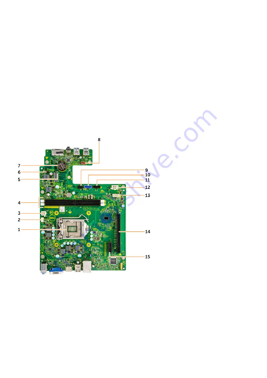
System board layout
1. Processor socket
2. CPU fan connector
3. PSU connector
4. Memory slot
5. WLAN card slot
6. Power button cable connector
7. Coin cell battery connector
8. System fan connector
9. SATA power connector
10. SATA0 connector
11. SATA2 connector
12. PSU connector
13. SATA1 connector
14. PCIex16 card slot
15. PCIex1 card slot
56
Disassembly and reassembly
Содержание D13S
Страница 1: ...Dell Vostro 3267 3268 Owner s Manual Regulatory Model D13S Regulatory Type D13S002 April 2022 Rev A02 ...
Страница 9: ...c Lift and remove the cover from the computer 3 Disassembly and reassembly 9 ...
Страница 13: ...Disassembly and reassembly 13 ...
Страница 16: ...16 Disassembly and reassembly ...
Страница 34: ...34 Disassembly and reassembly ...
Страница 39: ...3 Connect the heat sink assembly cable to the connector on the system board Disassembly and reassembly 39 ...
Страница 51: ...Disassembly and reassembly 51 ...


