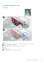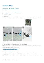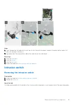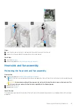
Steps
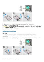
1. Ensure that the release lever is fully extended in the open position.
CAUTION:
You must place the processor correctly in the processor socket to avoid damage to the processor.
2. Align the pin-1 corner of the processor with the pin-1 corner of the processor socket, and then place the processor in the
processor socket.
NOTE:
The pin-1 corner of the processor has a triangle that aligns with the triangle on the pin-1 corner on the processor
socket. When the processor is properly seated, all four corners are aligned at the same height. If one or more corners of
the processor are higher than the others, the processor is not seated properly.
3. When the processor is fully seated in the socket, close the processor cover.
4. Press down and push the release lever under the securing tab to lock it.
Next steps
After working inside your computer
.
2. Install the
.
3. Install the
4. Install the
.
System board
System board connectors
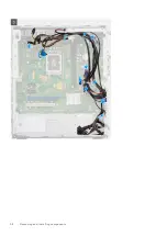
The following image indicates the connectors on your system board:
1. Intrusion switch
2. ATX CPU Power Connector
3. Memory module connectors
4. Power switch
5. Coin-cell battery
6. System power connector
Removing and installing components
51
Содержание ChengMing 3901 Tower
Страница 1: ...ChengMing 3901 Tower Service Manual Regulatory Model D32M Regulatory Type D32M002 April 2022 Rev A01 ...
Страница 53: ...Removing and installing components 53 ...
Страница 54: ...54 Removing and installing components ...
Страница 57: ...Removing and installing components 57 ...
Страница 58: ...58 Removing and installing components ...

