background image

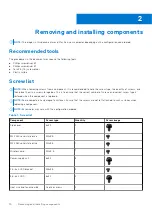
Table 1. Screw list (continued)

Component

Screw type

Quantity

Screw image

System board

6-32

M2x4

9

1

Major components of ChengMing 3901 Tower

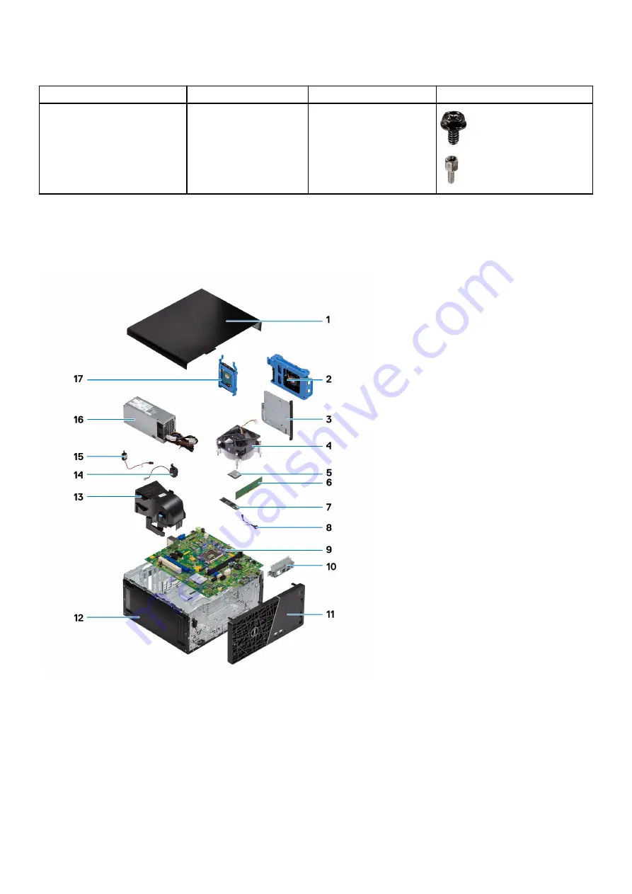
The following image shows the major components of ChengMing 3901 Tower .

1. Side cover

2. Battery

3. Optical disk drive

4. Heat sink and fan assembly

5. Processor

6. Memory module

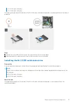
7. Solid-state drive

8. Power-button cable

9. System board

10. USB metal bracket

11. Front bezel

12. Chassis

13. Fan duct

14. Intrusion speaker

15. Intrusion switch

16. Power-supply unit

17. Hard drive

Removing and installing components

11

Содержание ChengMing 3901 Tower

Страница 1: ...ChengMing 3901 Tower Service Manual Regulatory Model D32M Regulatory Type D32M002 April 2022 Rev A01 ...

Страница 2: ...mage to hardware or loss of data and tells you how to avoid the problem WARNING A WARNING indicates a potential for property damage personal injury or death 2021 2022 Dell Inc or its subsidiaries All rights reserved Dell Technologies Dell and other trademarks are trademarks of Dell Inc or its subsidiaries Other trademarks may be trademarks of their respective owners ...

Страница 3: ... bezel 15 Memory modules 16 Removing the memory module 16 Installing the memory module 17 M 2 SSD card 18 Removing the M 2 2230 solid state drive 18 Installing the M 2 2230 solid state drive 19 Removing the M 2 2280 solid state drive 20 Installing the M 2 2280 solid state drive 21 Coin cell battery 22 Removing the coin cell battery 22 Installing the coin cell battery 23 WLAN module 24 Removing the...

Страница 4: ...rocessor 49 Installing the processor 50 System board 51 System board connectors 51 Removing the system board 52 Installing the system board 56 VGA port cover 60 Removing the VGA port cover 60 Installing the VGA port cover 60 Chapter 3 Drivers and downloads 62 Chapter 4 BIOS setup 63 BIOS overview 63 Entering BIOS setup program 63 Navigation keys 63 One time boot menu 64 System setup options 64 Upd...

Страница 5: ...ng the SupportAssist Pre Boot System Performance Check 78 Power Supply Unit Built in Self Test 78 System diagnostic lights 78 Recovering the operating system 79 Real Time Clock RTC reset 80 Backup media and recovery options 80 WiFi power cycle 80 Chapter 6 Getting help and contacting Dell 81 Contents 5 ...

Страница 6: ...touching anything inside your computer ground yourself by touching an unpainted metal surface such as the metal at the back of the computer While you work periodically touch an unpainted metal surface to dissipate static electricity which could harm internal components CAUTION When you disconnect a cable pull it by its connector or its pull tab not the cable itself Some cables have connectors with...

Страница 7: ...t strap should be secure and in full contact with your skin and ensure that you remove all jewelry such as watches bracelets or rings prior to bonding yourself and the equipment Electrostatic discharge ESD protection ESD is a major concern when you handle electronic components especially sensitive components such as expansion cards processors memory DIMMs and system boards Very slight charges can ...

Страница 8: ...t once per week A wrist strap tester is the best method for doing this test If you do not have your own wrist strap tester check with your regional office to find out if they have one To perform the test plug the wrist strap s bonding wire into the tester while it is strapped to your wrist and push the button to test A green LED is lit if the test is successful a red LED is lit and an alarm sounds...

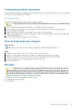
Страница 9: ...er working inside your computer About this task NOTE Leaving stray or loose screws inside your computer may severely damage your computer Steps 1 Replace all screws and ensure that no stray screws remain inside your computer 2 Connect any external devices peripherals or cables you removed before working on your computer 3 Replace any media cards discs or any other parts that you removed before wor...

Страница 10: ...rew storage box This is to ensure that the correct number of screws and correct screw type is restored when the component is replaced NOTE Some computers have magnetic surfaces Ensure that the screws are not left attached to such surfaces when replacing a component NOTE Screw color may vary with the configuration ordered Table 1 Screw list Component Screw type Quantity Screw image Side cover 6x32 ...

Страница 11: ...major components of ChengMing 3901 Tower 1 Side cover 2 Battery 3 Optical disk drive 4 Heat sink and fan assembly 5 Processor 6 Memory module 7 Solid state drive 8 Power button cable 9 System board 10 USB metal bracket 11 Front bezel 12 Chassis 13 Fan duct 14 Intrusion speaker 15 Intrusion switch 16 Power supply unit 17 Hard drive Removing and installing components 11 ...

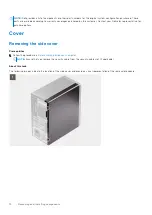
Страница 12: ... sales representative for purchase options Cover Removing the side cover Prerequisites 1 Follow the procedure in Before working inside your computer NOTE Ensure that you remove the security cable from the security cable slot if applicable About this task The following images indicate the location of the side cover and provide a visual representation of the removal procedure 12 Removing and install...

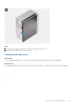
Страница 13: ...sis Installing the side cover Prerequisites If you are replacing a component remove the existing component before performing the installation procedure About this task The following image indicates the location of the side cover and provides a visual representation of the installation procedure Removing and installing components 13 ...

Страница 14: ...hassis 2 Slide the side cover towards the front of the system to install it 3 Tighten the two 6x32 thumbscrews to secure the side cover to the chassis Next steps 1 Follow the procedure in After working inside your computer 14 Removing and installing components ...

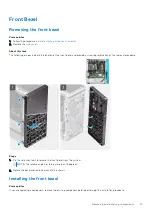
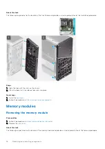
Страница 15: ...rovide a visual representation of the removal procedure Steps 1 Pry the retention tabs to release the front bezel from the system NOTE The release angle has to be more than 15 degrees 2 Rotate the bezel and remove away off the chassis Installing the front bezel Prerequisites If you are replacing a component remove the existing component before performing the installation procedure Removing and ins...

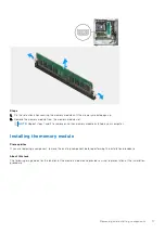
Страница 16: ...bs click into place Next steps 1 Install the side cover 2 Follow the procedure in After working inside your computer Memory modules Removing the memory module Prerequisites 1 Follow the procedure in Before working inside your computer 2 Remove the side cover About this task The following images indicate the location of the memory module and provide a visual representation of the removal procedure ...

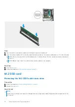
Страница 17: ...ny other memory module installed in your computer Installing the memory module Prerequisites If you are replacing a component remove the existing component before performing the installation procedure About this task The following image indicates the location of the memory module and provides a visual representation of the installation procedure Removing and installing components 17 ...

Страница 18: ...ll it NOTE Repeat steps 1 and 2 to install any other memory module in your computer Next steps 1 Install the side cover 2 Follow the procedure in After working inside your computer M 2 SSD card Removing the M 2 2230 solid state drive Prerequisites 1 Follow the procedure in Before working inside your computer 2 Remove the side cover About this task NOTE The M 2 card installed on your computer will ...

Страница 19: ... board Installing the M 2 2230 solid state drive Prerequisites If you are replacing a component remove the existing component before performing the installation procedure NOTE The M 2 card installed on your computer will depend on the configuration ordered Supported card configurations on the M 2 card slot M 2 2230 solid state drive M 2 2280 solid state drive About this task The following image in...

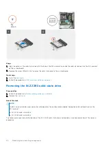
Страница 20: ...omputer Removing the M 2 2280 solid state drive Prerequisites 1 Follow the procedure in Before working inside your computer 2 Remove the side cover About this task NOTE The M 2 card installed on your computer will depend on the configuration ordered Supported card configurations on the M 2 card slot M 2 2230 solid state drive M 2 2280 solid state drive The following images indicate the location of...

Страница 21: ...emove the existing component before performing the installation procedure NOTE The M 2 card installed on your computer will depend on the configuration ordered Supported card configurations on the M 2 card slot M 2 2230 solid state drive M 2 2280 solid state drive About this task The following image indicates the location of the M 2 2280 solid state drive and provides a visual representation of th...

Страница 22: ...puter Coin cell battery Removing the coin cell battery Prerequisites 1 Follow the procedure in Before working inside your computer CAUTION Removing the coin cell battery resets the BIOS setup program s settings to default It is recommended that you note the BIOS setup program s settings before removing the coin cell battery 2 Remove the side cover About this task The following images indicate the ...

Страница 23: ...quisites If you are replacing a component remove the existing component before performing the installation procedure About this task The following image indicates the location of the coin cell battery and provides a visual representation of the installation procedure Removing and installing components 23 ...

Страница 24: ... in After working inside your computer WLAN module Removing the wireless card Prerequisites 1 Follow the procedure in Before working inside your computer 2 Remove the side cover About this task The following images indicate the location of the wireless card and provide a visual representation of the removal procedure 24 Removing and installing components ...

Страница 25: ...ling the wireless card Prerequisites If you are replacing a component remove the existing component before performing the installation procedure About this task The following image indicates the location of the wireless card and provides a visual representation of the installation procedure Steps 1 Connect the antenna cables to the wireless card The following table provides the antenna cable color...

Страница 26: ...and system board 6 Replace the screw M2x3 5 that secures the wireless card bracket to the wireless card and system board Next steps 1 Install the side cover 2 Follow the procedure in After working inside your computer Power supply unit Removing the power supply unit Prerequisites 1 Follow the procedure in Before working inside your computer 2 Remove the side cover 3 Remove the front bezel NOTE Not...

Страница 27: ...the chassis 5 Lift the power supply unit off the chassis Installing the power supply unit Prerequisites If you are replacing a component remove the existing component before performing the installation procedure WARNING The cables and ports on the back of the power supply unit are color coded to indicate the different power wattage Ensure that you plug in the cable to the correct port Failure to d...

Страница 28: ...ition 2 Replace the three 6 32 screws to secure the power supply unit to the chassis 3 Route the power cable through the routing guides on the chassis and connect the power cables to their respective connectors on the system board 4 Connect the 4 pin power cable to the system board Next steps 1 Install the front bezel 2 Install the side cover 3 Follow the procedure in After working inside your com...

Страница 29: ...er About this task The following images indicate the location of the 2 5 inch hard drive and provide a visual representation of the removal procedure Steps 1 Disconnect the data and power cables from the hard drive 2 Press the release tabs on the hard drive carrier and slide the hard drive carrier out of the hard drive cage Removing and installing components 29 ...

Страница 30: ...ng the hard drive bracket Prerequisites 1 Follow the procedure in Before working inside your computer 2 Remove the side cover 3 Remove the front bezel 4 Remove the 2 5 in hard drive assembly About this task The following images indicate the location of the hard drive bracket and provide a visual representation of the removal procedure NOTE ChengMing 3901 Tower supports two 2 5 inch hard drives 30 ...

Страница 31: ...t this task The following images indicate the location of the hard drive bracket and provide a visual representation of the installation procedure Steps 1 Place the 2 5 inch hard drive caddy into the bracket 2 Press to hold the tabs and snap the hard drive caddy into the chassis slot 3 Align and replace the two M3x3 5 screws insert the pins on the drive bracket with the slots on the drive NOTE Not...

Страница 32: ...ide cover 3 Install the front bezel 4 Follow the procedure in After working inside your computer Installing the 2 5 inch hard drive Prerequisites If you are replacing a component remove the existing component before performing the installation procedure About this task The following image indicates the location of the 2 5 inch hard drive and provides a visual representation of the installation pro...

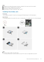
Страница 33: ...e Next steps 1 Install the side cover 2 Follow the procedure in After working inside your computer 3 5 inch hard drive Removing the 3 5 inch hard drive Prerequisites 1 Follow the procedure in Before working inside your computer 2 Remove the side cover 3 Remove the front bezel About this task The following images indicate the location of the 3 5 inch hard drive and provide a visual representation o...

Страница 34: ...g image indicates the location of the 3 5 inch hard drive and provides a visual representation of the installation procedure Steps 1 Locate the 3 5 inch hard drive slot on the chassis 2 Align the tabs on the hard drive cage with the slots on the chassis and slide the hard drive cage into the chassis 3 Replace the four 6 32 screws that secure the hard drive cage to the chassis 4 Connect the data an...

Страница 35: ...h the securing tab to release the optical drive carrier from the chassis 3 Push to slide the optical drive assembly out through the front of the computer 4 Gently pull and disconnect the optical drive bezel from the optical drive Installing the optical drive Prerequisites If you are replacing a component remove the existing component before performing the installation procedure About this task The...

Страница 36: ...e your computer Slim optical drive bracket Removing the slim ODD bracket Prerequisites 1 Follow the procedure in Before working inside your computer 2 Remove the side cover 3 Remove the optical drive About this task The following images indicate the location of the slim ODD bracket and provide a visual representation of the removal procedure 36 Removing and installing components ...

Страница 37: ...tallation procedure About this task The following images indicate the location of the slim ODD bracket and provide a visual representation of the installation procedure Steps 1 Align and place the slim ODD bracket on the ODD slots 2 Snap the slim ODD bracket into the slim ODD Next steps 1 Install the slim Optical Disk Drive 2 Install the side cover 3 Follow the procedure in After working inside yo...

Страница 38: ...procedure Steps 1 Press the retention tabs on both sides of the fan duct to release it 2 Pull and remove the fan duct from the computer Installing the fan duct Prerequisites If you are replacing a component remove the existing component before performing the installation procedure About this task The following image indicates the location of the fan duct and provides a visual representation of the...

Страница 39: ...the procedure in After working inside your computer Speaker Removing the intrusion speaker Prerequisites 1 Follow the procedure in Before working inside your computer 2 Remove the side cover About this task The following images indicate the location of the intrusion speaker and provide a visual representation of the removal procedure Removing and installing components 39 ...

Страница 40: ...lift the intrusion speaker along with the cable off the chassis Installing the intrusion speaker Prerequisites If you are replacing a component remove the existing component before performing the installation procedure About this task The following image indicates the location of the intrusion speaker and provides a visual representation of the installation procedure 40 Removing and installing com...

Страница 41: ...ard Next steps 1 Install the front bezel 2 Install the side cover 3 Follow the procedure in After working inside your computer Expansion card Removing the expansion card Prerequisites 1 Follow the procedure in Before working inside your computer 2 Remove the side cover About this task The following images indicate the location of the expansion card and provide a visual representation of the remova...

Страница 42: ...Steps 1 Pull the metal card retention latch from the computer 2 Push the release tab and lift the expansion card from the system board 42 Removing and installing components ...

Страница 43: ...the system board and press down until it is secured 2 Push the PCI bracket back to its position 3 Pull and close PCI bracket metal card retention latch to the computer Next steps 1 Install the side cover 2 Follow the procedure in After working inside your computer Removing and installing components 43 ...

Страница 44: ...n cable from the connector on the system board 2 Press the release tabs on the power button head and slide the power button cable out from the front side chassis of the computer 3 Pull the power button cable out from the computer Installing the power button Prerequisites If you are replacing a component remove the existing component before performing the installation procedure About this task The ...

Страница 45: ...nstall the front bezel 2 Install the fan duct 3 Install the side cover 4 Follow the procedure in After working inside your computer Intrusion switch Removing the intrusion switch Prerequisites 1 Follow the procedure in Before working inside your computer 2 Remove the side cover About this task The following image indicates the location of the intrusion switch and provides a visual representation o...

Страница 46: ...talling the intrusion switch Prerequisites If you are replacing a component remove the existing component before performing the installation procedure About this task The following image indicates the location of the intrusion switch and provides a visual representation of the installation procedure 46 Removing and installing components ...

Страница 47: ... working inside your computer NOTE The heat sink may become hot during normal operation Allow sufficient time for the heat sink to cool before you touch it CAUTION For maximum cooling of the processor do not touch the heat transfer areas on the heat sink The oils in your skin can reduce the heat transfer capability of the thermal grease 2 Remove the side cover 3 Remove the fan duct About this task...

Страница 48: ...sink assembly away from the system board Installing the heat sink and fan assembly Prerequisites If you are replacing a component remove the existing component before performing the installation procedure About this task The following image indicates the location of the heat sink and fan assembly and provide a visual representation of the installation procedure 48 Removing and installing component...

Страница 49: ...ll the side cover 3 Follow the procedure in After working inside your computer Processor Removing the processor Prerequisites 1 Follow the procedure in Before working inside your computer 2 Remove the side cover 3 Remove the fan duct 4 Remove the heat sink and fan assembly WARNING The processor might still be hot after the computer is shut down Allow the processor to cool down before removing it A...

Страница 50: ...et or allow any objects to fall on the pins in the socket 3 Gently lift the processor from the processor socket Installing the processor Prerequisites If you are replacing a component remove the existing component before performing the installation procedure About this task The following image indicates the location of the processor and provides a visual representation of the installation procedur...

Страница 51: ...igned at the same height If one or more corners of the processor are higher than the others the processor is not seated properly 3 When the processor is fully seated in the socket close the processor cover 4 Press down and push the release lever under the securing tab to lock it Next steps 1 Follow the procedure in After working inside your computer 2 Install the heat sink and fan assembly 3 Insta...

Страница 52: ...les correctly after you replace the system board NOTE Note the routing of all cables as you remove them so that you can route them correctly after you replace the system board For information about system board connectors see System board connectors 2 Remove the side cover 3 Remove the front bezel 4 Remove the M 2 2230 solid state drive or M 2 2280 solid state drive 5 Remove the wireless card 6 Re...

Страница 53: ...Removing and installing components 53 ...

Страница 54: ...54 Removing and installing components ...

Страница 55: ...e 2 Remove the single 6 32 screw that secures the side metal bracket to the chassis 3 Remove the side metal bracket away from the chassis 4 Disconnect the cables from their connectors on the system board Removing and installing components 55 ...

Страница 56: ... and lift the system board assembly at an angle out of the chassis Installing the system board Prerequisites If you are replacing a component remove the existing component before performing the installation procedure About this task The following image indicates the location of the system board and provides a visual representation of the installation procedure 56 Removing and installing components...

Страница 57: ...Removing and installing components 57 ...

Страница 58: ...58 Removing and installing components ...

Страница 59: ...ext steps 1 Install the processor 2 Install the coin cell battery 3 Install the expansion card 4 Install the memory module 5 Install the power suppy unit 6 Install the intrusion switch 7 Install the intrusion speaker 8 Install the power button 9 Install the heat sink and fan assembly 10 Install the fan duct 11 Install the optical drive 12 Install the 3 5 inch hard drive 13 Install the 2 5 inch har...

Страница 60: ...tion of the VGA port cover and provide a visual representation of the removal procedure Steps 1 Remove the two screws that secure the VGA port cover to the chassis 2 Lift and remove the VGA port cover away from the chassis Installing the VGA port cover Prerequisites If you are replacing a component remove the existing component before performing the installation procedure About this task The follo...

Страница 61: ... cover on the VGA port and align the screw holes 2 Replace the two screws to secure the VGA port cover to the chassis Next steps 1 Follow the procedure in After working inside your computer Removing and installing components 61 ...

Страница 62: ...rivers and downloads When troubleshooting downloading or installing drivers it is recommended that you read the Dell Knowledge Based article Drivers and Downloads FAQ 000123347 3 62 Drivers and downloads ...

Страница 63: ...ing base devices BIOS overview The BIOS manages data flow between the computer s operating system and attached devices such as hard disk video adapter keyboard mouse and printer Entering BIOS setup program About this task Turn on or restart your computer and press F2 immediately Navigation keys NOTE For most of the System Setup options changes that you make are recorded but do not take effect unti...

Страница 64: ... Manufacture Date Displays the manufacture date of the computer Ownership Date Displays the ownership date of the computer Express Service Code Displays the express service code of the computer Ownership Tag Displays the ownership tag of the computer Signed Firmware Update Displays whether the signed firmware update is enabled PROCESSOR Processor Type Displays the processor type Maximum Clock Spee...

Страница 65: ...ss of the computer Slot 2 Displays the status of the expansion slot Slot 2 of the computer Slot 3 Displays the status of the expansion slot Slot 3 of the computer Table 5 System setup options Boot Configuration menu Boot Configuration Boot Sequence Boot Mode UEFI only Displays the boot mode of this computer Boot Sequence Specifies the order that the BIOS searches the list of devices to find an ope...

Страница 66: ...ch between 12 hour and 24 hour clock Changes to the time take effect immediately Camera Enable Camera Enables or disables the camera By default Enable Camera is selected Audio Enables or disables all integrated audio controller Default ON Enable Microphone Enables or disables microphone By default Enable Microphone is selected Enable Internal Speaker Enables or disables internal speaker By default...

Страница 67: ...t Enablement Enables or disables the onboard drives Default SATA 0 is ON Default SATA 1 is ON Default SATA 3 is ON Default M 2 PCIe SDD 0 is ON SMART Reporting Enable or disable SMART Reporting during system startup Default OFF Drive Information Displays the information of various onboard drives Enable MediaCard Turn on or off all media cards or enable or disable the media card in read only state ...

Страница 68: ... provided Boot URL By default Auto Mode is selected Table 10 System setup options Power menu Power USB Wake Support Enable USB Wake Support Enables USB devices like a mouse or keyboard to wake the system from Standby Hibernation or Power Off state Default ON AC Behavior AC Recovery Configures the system response when power is restored after an unexpected loss of power Default Power OFF is selected...

Страница 69: ...rity Mitigation protection The operating system makes use of this feature to protect the secure environment crated by virtualization based security Default OFF Data Wipe on Next Boot Start Data Wipe Enable or disable data wipe cycle If enabled the BIOS will schedule a data wipe cycle for storage device s connected to the motherboard on the next reboot Any data on the storage device s cannot be rec...

Страница 70: ...SMM Security Mitigation Table 12 System setup options Passwords menu Passwords Admin Password Enables the user to set change or delete the administrator admin password The admin password enables several security features System Password Enables the user to set change or delete the system password Password Configuration Upper Case Letter Enforces password restriction that the password must contain ...

Страница 71: ...ternal USB key Default ON NOTE BIOS Recovery from Hard Drive is not available for Self encrypting drives SED BIOS Downgrade Allow BIOS Downgrade Controls flashing of the system firmware to previous revisions Default ON SupportAssist OS Recovery SupportAssist OS Recovery Enables or disables the boot flow for SupportAssist OS Recovery tool in the event of certain system errors Default ON BIOSConnect...

Страница 72: ...m setup options Keyboard menu Keyboard Keyboard Errors Enable Keyboard Error Detection Enables or disables report of keyboard related errors when the computer boots Default ON Numlock LED Enable Numlock LED Enables or disables Numlock when the computer boots Default ON Table 16 System setup options Pre boot Behavior menu Pre boot Behavior Warnings and Errors Warnings and Errors Selects an action o...

Страница 73: ...es or disables the Intel SpeedStep Technology to dynamically adjust processor voltage and core frequency decreasing average power consumption and heat production Default ON C States Control Enable C State Control Enables or disables the CPU s ability to enter and exit low power states Default ON Intel Turbo Boost Technology Enable Intel Turbo Boost Technology Enabled or disabled the Intel TurboBoo...

Страница 74: ... on screen instructions For more information search in the Knowledge Base Resource at www dell com support Updating the BIOS in Linux and Ubuntu To update the system BIOS on a computer that is installed with Linux or Ubuntu see the knowledge base article 000131486 at www dell com support Updating the BIOS using the USB drive in Windows About this task CAUTION If BitLocker is not suspended before u...

Страница 75: ...ate your BIOS from the F12 One Time boot menu you need the following USB drive formatted to the FAT32 file system key does not have to be bootable BIOS executable file that you downloaded from the Dell Support website and copied to the root of the USB drive AC power adapter that is connected to the computer Functional computer battery to flash the BIOS Perform the following steps to perform the BI...

Страница 76: ... the changes as prompted by the pop up message 5 Press Y to save the changes The computer restarts Deleting or changing an existing system setup password Prerequisites Ensure that the Password Status is Unlocked in the System Setup before attempting to delete or change the existing System and or Setup password You cannot delete or change an existing System or Setup password if the Password Status ...

Страница 77: ... one minute 5 Replace the coin cell battery 6 Connect the battery cable to the system board 7 Replace the side cover Clearing BIOS System Setup and System passwords About this task To clear the system or BIOS passwords contact Dell technical support as described at www dell com contactdell NOTE For information on how to reset Windows or application passwords refer to the documentation accompanying...

Страница 78: ... are performed For more information see https www dell com support kbdoc 000180971 Running the SupportAssist Pre Boot System Performance Check Steps 1 Turn on your computer 2 As the computer boots press the F12 key as the Dell logo appears 3 On the boot menu screen select the Diagnostics option 4 Click the arrow at the bottom left corner Diagnostics front page is displayed 5 Click the arrow in the...

Страница 79: ...rd 3 5 EC ran into power sequencing failure Run the PSU built in self test BIST to identify the issue reseat the cables If nothing works replace the system board power supply or cabling 3 6 Flash corruption detected by SBIOS Flash corruption detected by system BIOS If problem persists replace the system board 3 7 Timeout waiting on ME to reply to HECI message Timeout waiting on Management Engine t...

Страница 80: ...HDD Password Key Databases System Logs NOTE The IT administrator s vPro account and password on the system will be un provisioned The system needs to go through the setup and configuration process again to reconnect it to the vPro server The below items may or may not reset based on your custom BIOS setting selections Boot List Enable Legacy Option ROMs Secure Boot Enable Allow BIOS Downgrade Back...

Страница 81: ... Service Tag or Express Service Code at www dell com support For more information on how to find the Service Tag for your computer see Locate the Service Tag on your computer Dell knowledge base articles for a variety of computer concerns 1 Go to www dell com support 2 On the menu bar at the top of the Support page select Support Knowledge Base 3 In the Search field on the Knowledge Base page type...

Отзывы: