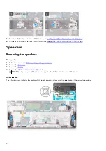
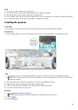
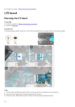
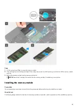
background image

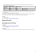
The following table provides the antenna-cable color scheme for the wireless card that is supported by your computer.

Table 2. Antenna-cable color scheme


Connectors on the

wireless card

Antenna-cable color

Silkscreen marking

Main

White

MAIN

 (white triangle)

Auxiliary

Black

AUX

 (black triangle)

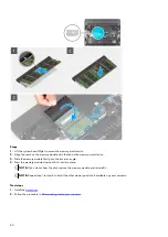
3. Align the notch on the wireless card with the tab on the wireless-card slot and insert the wireless card at an angle into the

wireless-card slot.

4. Align and place the wireless-card bracket on the wireless card.
5. Replace the screw (M2x4) that secures the wireless-card bracket to the system board and palm-rest and keyboard assembly.
6. Secure the wireless-card cables to the palm-rest and keyboard assembly with the keyboard Mylar.

Next steps
1. 
Install the 

base cover

.

2. Follow the procedure in 

After working inside your computer

.

Rear-I/O cover

Removing the rear I/O-cover

Prerequisites
1. 
Follow the procedure in 

Before working inside your computer

.

2. Remove the 

base cover

.

About this task
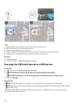
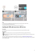
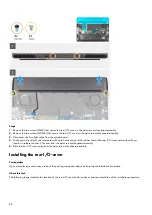
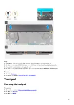
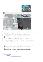
The following image indicates the location of the rear I/O-cover and provides a visual representation of the removal procedure.

43

Содержание Alienware m15 R6

Страница 1: ...Alienware m15 R6 Service Manual Regulatory Model P109F Regulatory Type P109F001 P109F004 April 2021 Rev A00 ...

Страница 2: ...ential damage to hardware or loss of data and tells you how to avoid the problem WARNING A WARNING indicates a potential for property damage personal injury or death 2021 Dell Inc or its subsidiaries All rights reserved Dell EMC and other trademarks are trademarks of Dell Inc or its subsidiaries Other trademarks may be trademarks of their respective owners ...

Страница 3: ...olid state drive 24 Removing the 2230 solid state drive in SSD slot one 24 Installing the 2230 solid state drive in SSD slot one 25 Removing the 2280 solid state drive in SSD slot one 26 Installing the 2280 solid state drive in SSD slot one 27 Removing the 2230 solid state drive in SSD slot two 28 Installing the 2230 solid state drive in SSD slot two 29 Removing the 2280 solid state drive in SSD s...

Страница 4: ...heat sink assembly 65 Installing the heat sink assembly 66 USB board 68 Removing the USB board 68 Installing the USB board 69 Power button 70 Removing the power button 70 Installing the power button 71 Palm rest and keyboard assembly 72 Removing the palm rest and keyboard assembly 72 Installing the palm rest and keyboard assembly 73 Chapter 3 Drivers and downloads 74 Chapter 4 System setup 75 BIOS...

Страница 5: ...Flashing the BIOS 90 Backup media and recovery options 90 WiFi power cycle 91 Drain residual flea power perform hard reset 91 Chapter 6 Getting help and contacting Alienware 92 5 ...

Страница 6: ...liance WARNING Disconnect your computer from all power sources before opening the computer cover or panels After you finish working inside the computer replace all covers panels and screws before connecting your computer to an electrical outlet CAUTION To avoid damaging the computer ensure that the work surface is flat dry and clean CAUTION To avoid damaging the components and cards handle them by...

Страница 7: ...npacking a static sensitive component from its shipping carton do not remove the component from the anti static packing material until you are ready to install the component Before unwrapping the anti static packaging ensure that you discharge static electricity from your body Before transporting a static sensitive component place it in an anti static container or packaging ESD field service kit T...

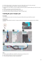
Страница 8: ... should be removed from packaging only at an ESD protected work surface and parts should never be placed on top of the ESD bag because only the inside of the bag is shielded Always place parts in your hand on the ESD mat in the system or inside an anti static bag Transporting Sensitive Components When transporting ESD sensitive components such as replacement parts or parts to be returned to Dell i...

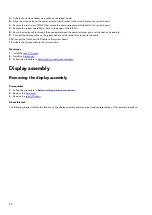
Страница 9: ...ensure that the correct number of screws and correct screw type is restored when the component is replaced NOTE Some computers have magnetic surfaces Ensure that the screws are not left attached to such surfaces when replacing a component NOTE Screw color may vary with the configuration ordered Table 1 Screw list Component Screw type Quantity Screw image Base cover M2 5x1 7 captive screw 4 Base co...

Страница 10: ...ouchpad M2x2 2 Keyboard controller board M2x2 1 Rear I O cover M2x4 2 Rear I O cover M2 5x5 2 Power adapter port bracket M2x4 2 System board M2x4 9 Heat sink assembly M2x4 6 USB board M2x4 2 Power button M2x2 3 Major components of Alienware m15 R6 The following image shows the major components of Alienware m15 R6 10 ...

Страница 11: ...1 Base cover 2 2280 solid state drive thermal shield 3 2280 solid state drive 4 2230 solid state drive thermal shield 5 2230 solid state drive 6 Left fan 11 ...

Страница 12: ...board 26 USB Type C port bracket NOTE Dell provides a list of components and their part numbers for the original system configuration purchased These parts are available according to warranty coverages purchased by the customer Contact your Dell sales representative for purchase options Base cover Removing the base cover Prerequisites 1 Follow the procedure in Before working inside your computer A...

Страница 13: ...13 ...

Страница 14: ...rews M2 5x8 5 3 5 that secure the base cover to the palm rest and keyboard assembly 3 Loosen the four captive screws M2 5x1 7 3 3 that secure the base cover to the palm rest and keyboard assembly NOTE Loosening the four screws creates a gap which can be used to pry and lift the base cover off the palm rest and keyboard assembly 14 ...

Страница 15: ...remove any other component from your computer 6 Disconnect the battery cable from the system board 7 Turn your computer over and press the power button for 20 seconds to drain the flea power Installing the base cover Prerequisites If you are replacing a component remove the existing component before performing the installation procedure About this task The following images indicate the location of...

Страница 16: ...16 ...

Страница 17: ...ly 3 Replace the two screws M2 5x5 that secure the base cover to the palm rest and keyboard assembly 4 Tighten the two captive screws M2 5x8 5 3 5 that secure the base cover to the palm rest and keyboard assembly 5 Tighten the four captive screws M2 5x1 7 3 3 that secure the base cover to the palm rest and keyboard assembly Next steps 1 Follow the procedure in After working inside your computer 17...

Страница 18: ...roduct are not lost or misplaced to prevent accidental puncture or damage to the battery and other system components If the battery gets stuck inside your computer as a result of swelling do not try to release it as puncturing bending or crushing a lithium ion battery can be dangerous In such an instance contact Dell technical support for assistance See www dell com contactdell Always purchase gen...

Страница 19: ... battery 3 Lift the battery cable off the battery Installing the battery cable Prerequisites If you are replacing a component remove the existing component before performing the installation procedure About this task The following image indicates the location of the battery cable and provides a visual representation of the installation procedure 19 ...

Страница 20: ...ttery Next steps 1 Install the battery 2 Install the base cover 3 Follow the procedure in After working on your computer Removing the battery Prerequisites 1 Follow the procedure in Before working inside your computer 2 Remove the base cover About this task The following image indicates the location of the battery and provides a visual representation of the removal procedure 20 ...

Страница 21: ... four screws M2x4 that secure the battery to the palm rest and keyboard assembly 3 Remove the four screws M2x3 that secure the battery to the palm rest and keyboard assembly 4 Lift the battery off the palm rest and keyboard assembly Installing the battery Prerequisites If you are replacing a component remove the existing component before performing the installation procedure About this task The fo...

Страница 22: ...t has to be purchased separately Next steps 1 Install the base cover 2 Follow the procedure in After working inside your computer Battery cable Lithium ion battery precautions CAUTION Exercise caution when handling Lithium ion batteries Discharge the battery completely before removing it Disconnect the AC power adapter from the system and operate the computer solely on battery power the battery is...

Страница 23: ...equisites 1 Follow the procedure in Before working inside your computer 2 Remove the base cover 3 Remove the battery NOTE If battery is disconnected from system board for service then there is a delay during system boot as the computer undergoes RTC battery reset About this task The following images indicate the location of the battery cable and provide a visual representation of the removal proce...

Страница 24: ...stall the base cover 3 Follow the procedure in After working on your computer Solid state drive Removing the 2230 solid state drive in SSD slot one Prerequisites 1 Follow the procedure in Before working inside your computer CAUTION Solid state drives are fragile Exercise care when handling the solid state drive CAUTION To avoid data loss do not remove the solid state drive while the computer is in...

Страница 25: ...requisites If you are replacing a component remove the existing component before performing the installation procedure About this task NOTE This procedure applies only to computers shipped with a 2230 solid state drive installed in SSD slot one NOTE Depending on the configuration ordered your computer may support either 2230 solid state drive or 2280 solid state drive in SSD slot one If you want t...

Страница 26: ...n After working inside your computer Removing the 2280 solid state drive in SSD slot one Prerequisites 1 Follow the procedure in Before working inside your computer 2 CAUTION Solid state drives are fragile Exercise care when handling the solid state drive CAUTION To avoid data loss do not remove the solid state drive while the computer is in sleep or on state 3 Remove the base cover About this tas...

Страница 27: ...orming the installation procedure About this task NOTE This procedure applies only to computers shipped with a 2280 solid state drive installed in SSD slot one NOTE Depending on the configuration ordered your computer may support either 2230 solid state drive or 2280 solid state drive in SSD slot one If you want to replace your 2230 solid state drive with a 2280 solid state drive see procedure to ...

Страница 28: ...e in SSD slot two Prerequisites 1 Follow the procedure in Before working inside your computer 2 CAUTION Solid state drives are fragile Exercise care when handling the solid state drive CAUTION To avoid data loss do not remove the solid state drive while the computer is in sleep or on state 3 Remove the base cover About this task NOTE This procedure applies only to computers shipped with a 2230 sol...

Страница 29: ...forming the installation procedure About this task NOTE This procedure applies only to computers shipped with a 2230 solid state drive installed in SSD slot two NOTE Depending on the configuration ordered your computer may support either 2230 solid state drive or 2280 solid state drive in SSD slot two If you want to replace your 2280 solid state drive with a 2230 solid state drive see procedure to...

Страница 30: ...ot two Prerequisites 1 Follow the procedure in Before working inside your computer 2 CAUTION Solid state drives are fragile Exercise care when handling the solid state drive CAUTION To avoid data loss do not remove the solid state drive while the computer is in sleep or on state 3 Remove the base cover About this task NOTE This procedure applies only to computers shipped with a 2280 solid state dr...

Страница 31: ...forming the installation procedure About this task NOTE This procedure applies only to computers shipped with a 2280 solid state drive installed in SSD slot two NOTE Depending on the configuration ordered your computer may support either 2230 solid state drive or 2280 solid state drive in SSD slot two If you want to replace your 2280 solid state drive with a 2230 solid state drive see procedure to...

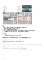
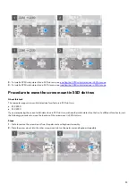
Страница 32: ...base cover 2 Follow the procedure in After working inside your computer Procedure to move the screw mount in SSD slot one About this task This computer supports two solid state drive form factors in SSD slot one M 2 2230 M 2 2280 If you are replacing the current solid state drive in SSD slot one with another solid state drive that is of a different form factor see the following procedure to move t...

Страница 33: ...k This computer supports two solid state drive form factors in SSD slot two M 2 2230 M 2 2280 If you are replacing the current solid state drive in SSD slot two with another solid state drive that is of a different form factor see the following procedure to move the location of the screw mount in SSD slot two Steps 1 Slide to remove the screw mount from the palm rest and keyboard assembly 2 Slide ...

Страница 34: ...rs Removing the speakers Prerequisites 1 Follow the procedure in Before working inside your computer 2 Remove the base cover 3 Remove the battery 4 Remove the 2280 solid state drive in SSD slot 2 NOTE This step is required if the device is shipped with a 2280 solid state drive in SSD slot 2 About this task The following image indicates the location of the speakers and provides a visual representat...

Страница 35: ...s and provides a visual representation of the installation procedure Steps 1 Using the alignment posts and rubber grommets place the speakers in the slots on the palm rest and keyboard assembly NOTE If the rubber grommets are pushed out of the speakers when removing the speakers push them back in place before replacing the speakers 2 Route the speaker cable through the routing guides on the palm r...

Страница 36: ...is task The following image indicates the location of the I O board and provides a visual representation of the removal procedure Steps 1 Lift the system board Mylar and open the latch to disconnect the I O board cable from the system board 2 Open the latch to disconnect the I O board cable from the I O board 3 Remove the screw M2x4 that secures the I O board to the palm rest and keyboard assembly...

Страница 37: ...bly NOTE If your device is shipped with the NVIDIA GeForce RTX 3050 Ti discrete GPU controller skip this step and see step 5 5 Lift the I O board off the palm rest and keyboard assembly Installing the I O board Prerequisites If you are replacing a component remove the existing component before performing the installation procedure About this task The following image indicates the location of the I...

Страница 38: ...NVIDIA GeForce RTX 3050 Ti discrete GPU controller skip this step and see step 5 5 Connect the I O board cable to the I O board and close the latch to secure the cable 6 Connect the I O board cable to the system board and close the latch to secure the cable 7 Place the system board Mylar back on the system board Next steps 1 Install the base cover 2 Follow the procedure in After working inside you...

Страница 39: ...ule from the memory module slot NOTE Repeat step 1 and step 3 to remove the other memory module if installed on your computer Installing the memory module Prerequisites If you are replacing a component remove the existing component before performing the installation procedure About this task The following image indicates the location of the memory module and provides a visual representation of the...

Страница 40: ...module firmly into the slot at an angle 4 Press the memory module down until it clicks into place NOTE If you do not hear the click remove the memory module and reinstall it NOTE Repeat step 1 to step 4 to install the other memory module if available on your computer Next steps 1 Install the base cover 2 Follow the procedure in After working inside your computer 40 ...

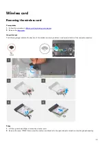
Страница 41: ...e cover About this task The following image indicates the location of the wireless card and provides a visual representation of the removal procedure Steps 1 Lift the system board Mylar to access the wireless card 2 Remove the screw M2x4 that secures the wireless card bracket to the system board and palm rest and keyboard assembly 41 ...

Страница 42: ...ss card Prerequisites If you are replacing a component remove the existing component before performing the installation procedure About this task The following image indicates the location of the wireless card and provides a visual representation of the installation procedure Steps 1 Lift the system board Mylar to access the wireless card slot 2 Connect the antenna cables to the wireless card 42 ...

Страница 43: ...ce the wireless card bracket on the wireless card 5 Replace the screw M2x4 that secures the wireless card bracket to the system board and palm rest and keyboard assembly 6 Secure the wireless card cables to the palm rest and keyboard assembly with the keyboard Mylar Next steps 1 Install the base cover 2 Follow the procedure in After working inside your computer Rear I O cover Removing the rear I O...

Страница 44: ... and push the rubber feet on the rear I O cover outwards with your thumbs to release the rear I O cover from the palm rest and keyboard assembly 5 Slide the rear I O cover away from the palm rest and keyboard assembly Installing the rear I O cover Prerequisites If you are replacing a component remove the existing component before performing the installation procedure About this task The following ...

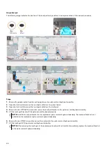
Страница 45: ... Connect the Tron light cable to the system board 4 Replace the two screws M2 5x5 that secure the rear I O cover to the palm rest and keyboard assembly Next steps 1 Install the base cover 2 Follow the procedure in After working inside your computer Touchpad Removing the touchpad Prerequisites 1 Follow the procedure in Before working inside your computer 2 Remove the base cover 3 Remove the battery...

Страница 46: ...re the touchpad bracket to the palm rest and keyboard assembly 5 Lift the touchpad bracket off the palm rest and keyboard assembly NOTE Install the touchpad bracket on the replacement palm rest and keyboard assembly The touchpad bracket is not available on the replacement palm rest and keyboard assembly 6 Remove the two M2x2 screws that secure the touchpad to the palm rest and keyboard assembly 7 ...

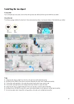
Страница 47: ... assembly 2 Replace the two M2x2 screws that secure the touchpad to the palm rest and keyboard assembly 3 Connect the touchpad cable to the system board and close the latch to secure the cable 4 Connect the touchpad cable to the touchpad and close the latch to secure the cable 5 Align and place the touchpad bracket into the slot on the palm rest and keyboard assembly 6 Replace the two M2 5x2 5 scr...

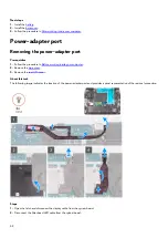
Страница 48: ...w the procedure in Before working inside your computer 2 Remove the base cover 3 Remove the rear I O cover About this task The following image indicates the location of the power adapter port and provides a visual representation of the removal procedure Steps 1 Open the latch and disconnect the display cable from the system board 2 Disconnect the Alienhead LED cable from the system board 48 ...

Страница 49: ... the system board 8 Peel and lift the power adapter port along with its cable off the system board Installing the power adapter port Prerequisites If you are replacing a component remove the existing component before performing the installation procedure About this task The following image indicates the location of the power adapter port and provides a visual representation of the installation pro...

Страница 50: ... the display cable on the system board and close the latch to secure the cable 10 Connect the Alienhead LED cable to the system board 11 Adhere the display cable to the system board Next steps 1 Install the rear I O cover 2 Install the base cover 3 Follow the procedure in After working inside your computer Display assembly Removing the display assembly Prerequisites 1 Follow the procedure in Befor...

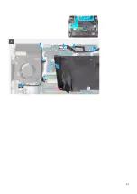
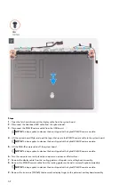
Страница 51: ...51 ...

Страница 52: ...ipped with a hybrid RGB IR camera module 5 Lift the RGB IR camera cable off the system board NOTE This step applies to devices that are shipped with a hybrid RGB IR camera module 6 Turn the computer over and place the computer on a clean and flat surface 7 Remove the display cable from the routing guides on the palm rest and keyboard assembly 8 Remove the RGB IR camera cable from the routing guide...

Страница 53: ... the display assembly Installing the display assembly Prerequisites If you are replacing a component remove the existing component before performing the installation procedure About this task The following image indicates the location of the display assembly and provides a visual representation of the installation procedure 53 ...

Страница 54: ...54 ...

Страница 55: ...r over 6 Connect the display cable to the connector on the system board and close the latch to secure the cable 7 Connect the Alienhead LED cable to the system board 8 Adhere the display cable to the system board 9 Lift the system board Mylar 10 Adhere the RGB IR camera cable to the system board along the edge of right fan of the heatsink assembly NOTE This step applies to devices that are shipped...

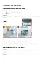
Страница 56: ...nect the keyboard cable from the keyboard controller board 3 Open the latch and disconnect the keyboard controller board cable from the keyboard controller board 4 Remove the screw M2x2 that secures the keyboard controller board to the palm rest and keyboard assembly 5 Remove the keyboard controller board off the palm rest and keyboard assembly Installing the keyboard controller board Prerequisite...

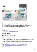
Страница 57: ...teps 1 Install the battery 2 Install the base cover 3 Follow the procedure in After working inside your computer System board Removing the system board Prerequisites 1 Follow the procedure in Before working inside your computer NOTE Replacing the system board removes any changes that you have made to the BIOS using the BIOS setup program Make the appropriate changes again after you replace the sys...

Страница 58: ...cable 3 Speaker cable 4 I O board cable 5 Power adapter port cable 6 Touchpad cable 7 Keyboard controller board cable 8 RGB IR camera cable NOTE This applies to devices that are shipped with a hybrid RGB IR camera module 9 Power button board cable The following image indicates the location of the system board and provides a visual representation of the removal procedure 58 ...

Страница 59: ...59 ...

Страница 60: ...le from the system board 12 Open the latch and disconnect the keyboard controller board cable from the system board 13 Open the latch and disconnect the power button board cable from the USB board 14 Open the latch and disconnect the RGB IR camera cable from the USB board NOTE This step is applicable for devices that are shipped with a hybrid RGB IR camera module 15 Peel the RGB IR camera cable fr...

Страница 61: ...ps you are left with the system board Installing the system board Prerequisites If you are replacing a component remove the existing component before performing the installation procedure NOTE When replacing accessing other parts the system board can be installed with the heat sink attached in order to simplify the procedure and preserve the thermal bond between the system board and heat sink 61 ...

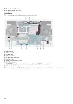
Страница 62: ... after you replace the system board About this task The following image indicates the connectors on your system board 1 Display cable 2 Alienhead LED cable 3 Speaker cable 4 I O board cable 5 Power adapter port cable 6 Touchpad cable 7 Keyboard cable 8 RGB IR camera cable NOTE This applies to devices that are shipped with a hybrid RGB IR camera module 9 Power button cable The following image indic...

Страница 63: ...63 ...

Страница 64: ...d LED cable to the system board 11 Adhere the display cable to the system board 12 Adhere the power adapter port cable to the system board and connect the power adapter port cable to the system board 13 Connect the I O board cable to the system board and close the latch to secure the cable 14 Connect the speaker cable to the system board 15 Connect the touchpad cable to the system board and close ...

Страница 65: ...he thermal grease NOTE The heat sink may become hot during normal operation Allow sufficient time for the heat sink to cool before you touch it 2 Remove the base cover 3 Remove the 2230 solid state drive or 2280 solid state drive in SSD slot one whichever applicable 4 Remove the 2230 solid state drive or 2280 solid state drive in SSD slot two whichever applicable 5 Remove the I O board 6 Remove th...

Страница 66: ...ly off the system board Installing the heat sink assembly Prerequisites If you are replacing a component remove the existing component before performing the installation procedure About this task The following image indicates the location of the heat sink assembly and provides a visual representation of the installation procedure CAUTION Incorrect alignment of the heat sink can damage the system b...

Страница 67: ...heat sink assembly to the system board 4 Turn the system board over and connect the left and right fan cables Next steps 1 Follow the procedure from step 4 to step 20 in Installing the system board 2 Install the rear I O cover 3 Install the battery 4 Install the wireless card 5 Install the memory module 6 Install the I O board 7 Install the 2230 solid state drive or 2280 solid state drive in SSD s...

Страница 68: ...e 5 Remove the I O board 6 Remove the memory module 7 Remove the wireless card 8 Remove the battery 9 Remove the rear I O cover 10 Follow the procedure from step 1 to step 16 in Removing the system board NOTE System board can be removed with the heat sink I O board and USB board attached About this task The following image indicates the location of the USB board and provides a visual representatio...

Страница 69: ...Replace the two screws M2x4 that secure the USB board to the system board Next steps 1 Follow the procedure from step 4 to step 20 in Installing the system board 2 Install the rear I O cover 3 Install the battery 4 Install the wireless card 5 Install the memory module 6 Install the I O board 7 Install the 2230 solid state drive or 2280 solid state drive in SSD slot one whichever applicable 8 Insta...

Страница 70: ... display assembly 9 Remove the battery 10 Remove the rear I O cover 11 Follow the procedure from step 1 to step 16 in Removing the system board NOTE System board can be removed with the heat sink assembly and USB board attached About this task The following images indicate the location of the power button and provide a visual representation of the removal procedure Steps 1 Remove the three screws ...

Страница 71: ...and keyboard assembly 3 Replace the three screws M2x2 that secure the power button bracket to the palm rest and keyboard assembly Next steps 1 Follow the procedure from step 4 to step 20 in Installing the system board 2 Install the rear I O cover 3 Install the battery 4 Install the display assembly 5 Install the wireless card 6 Install the memory module 7 Install the I O board 8 Install the 2230 s...

Страница 72: ...less card 8 Remove the display assembly 9 Remove the battery 10 Remove the rear I O cover 11 Remove the touchpad 12 Follow the procedure from step 1 to step 16 in Removing the system board NOTE System board can be removed with the heat sink and USB board attached 13 Remove the power button About this task After performing the steps in the pre requisites we are left with the palm rest and keyboard ...

Страница 73: ...nt palm rest and keyboard assembly Next steps 1 Install the power button 2 Follow the procedure from step 4 to step 20 in Installing the system board 3 Install the touchpad 4 Install the rear I O cover 5 Install the battery 6 Install the display assembly 7 Install the wireless card 8 Install the memory module 9 Install the I O board 10 Install the 2230 solid state drive or 2280 solid state drive i...

Страница 74: ...Drivers and downloads When troubleshooting downloading or installing drivers it is recommended that you read the Dell Knowledge Based article Drivers and Downloads FAQ SLN128938 74 ...

Страница 75: ... keyboard is initialized This prompt can appear very quickly so you must watch for it and then press F2 If you press F2 before the F2 prompt this keystroke is lost If you wait too long and the operating system logo appears continue to wait until you see the desktop Then turn off your computer and try again Navigation keys NOTE For most of the System Setup options changes that you make are recorded...

Страница 76: ...er Express Service Code Displays the express service code of the computer Ownership Tag Displays the ownership tag of the computer Signed Firmware Update Displays whether the signed firmware update is enabled Default Enabled BATTERY Primary Battery Level Displays the battery level Battery State Displays the battery state Health Displays the battery health information AC Adapter Displays whether an...

Страница 77: ...solution of the computer Video BIOS Version Displays the video BIOS version of the computer Audio Controller Displays the audio controller information of the computer Bluetooth Device Displays whether a Bluetooth device is installed in the computer LOM MAC Address Displays the MAC address of the LAN on Motherboard LOM dGPU Video Controller Displays the discrete graphics controller Table 4 System s...

Страница 78: ...ult Enable External USB Ports is selected Enable USB Boot Support Enables or disables booting from USB mass storage devices such as external hard drive optical drive and USB drive By default Enable USB Boot Support is selected Enable Thunderbolt Boot Support Enables or disables Thunderbolt adapter peripheral devices and USB devices connected to the Thunderbolt adapter to be used during BIO s pre b...

Страница 79: ...d Graphics Advanced Optimus when available When turned on the system allows both integrated and discrete graphics controllers to work together for optimized capability and battery life When turned off the discrete graphics controller will drive all displays to prioritize graphics capability over battery life Default On NOTE Linux is not supported with Hybrid Graphics enabled Table 8 System setup o...

Страница 80: ...SB PowerShare Enables external devices such as phones and portable music players to be powered or charged using the stored system battery Default OFF Thermal Management Thermal Management Enables the cooling fan and processor heat management to adjust system performance noise and temperature Default Optimized Standard settings for cooling fan and processor heat management This setting is a balance...

Страница 81: ... to the system board on the next reboot Default OFF Absolute Absolute Enables disables or permanently disable the BIOS module interface of the optional Absolute Persistence Module service from Absolute Software Default Enabled UEFI Boot Path Security UEFI Boot Path Security Determines if the system will prompt the user to enter the admin password if set when booting to a UEFI boot path device frim...

Страница 82: ...s the user from entering BIOS Setup when an Admin Password is set Default OFF Master Password Lockout Enable Master Password Lockout Enables or disables master password support Default OFF NOTE Hard drive passwords must be cleared before the setting can be changed Allow Non Admin PSID Revert Enable Allow Non Admin PSID Revert Controls access to the Physical Security ID PSID revert of NVMe hard dri...

Страница 83: ...t System Resolution Console and for Dell operating system Recovery tool Default 2 Table 13 System setup options System Management menu System Management Service Tag Displays the Service Tag of the computer Asset Tag Creates a system Asset Tag that can be used by an IT administrator to uniquely identify a particular system Once set in BIOS the Asset Tag cannot be changed AC Behavior Wake on AC Enab...

Страница 84: ...Selecting the incorrect language may cause the keyboard and lighting malfunction Table 15 System setup options Pre boot Behavior menu Pre boot Behavior Adapter warnings Enable Adapter warnings Enables or disables the computer to display adapter warning messages when adapters with too little power capacity are detected Default ON Warnings and Errors Warnings and Errors Selects an action on encounte...

Страница 85: ...decreasing average power consumption and heat production Default ON C States Control Enable C State Control Enables or disables the CPU s ability to enter and exit low power states Default ON Enable Adaptive C States for Discrete Graphics Allows to dynamically detect high usage of discrete graphics and adjust system parameters for higher performance during that time period Default ON Intel Turbo B...

Страница 86: ...n to your system Setup password Password that you must enter to access and make changes to the BIOS settings of your computer You can create a system password and a setup password to secure your computer CAUTION The password features provide a basic level of security for the data on your computer CAUTION Anyone can access the data stored on your computer if it is not locked and left unattended NOT...

Страница 87: ...em Security and press Enter The System Security screen is displayed 2 In the System Security screen verify that Password Status is Unlocked 3 Select System Password alter or delete the existing system password and press Enter or Tab 4 Select Setup Password alter or delete the existing setup password and press Enter or Tab NOTE If you change the System and or Setup password re enter the new passwor...

Страница 88: ...NOTE For information on how to reset Windows or application passwords refer to the documentation accompanying Windows or your application 88 ...

Страница 89: ...er and battery status light patterns and associated problems NOTE The following diagnostic light codes and recommended solutions are intended for Dell service technicians to troubleshoot problems You should only perform troubleshooting and repairs as authorized or directed by the Dell technical support team Damage due to servicing that is not authorized by Dell is not covered by your warranty Tabl...

Страница 90: ...e BIOS About this task You may need to flash update the BIOS when an update is available or when you replace the system board Follow these steps to flash the BIOS Steps 1 Turn on your computer 2 Go to www dell com support 3 Click Product support enter the Service Tag of your computer and then click Submit NOTE If you do not have the Service Tag use the auto detect feature or manually browse for yo...

Страница 91: ...d the battery is removed For your safety and to protect the sensitive electronic components in your computer you are requested to drain residual flea power before removing or replacing any components in your computer Draining residual flea power also known as a performing a hard reset is also a common troubleshooting step if your computer does not power on or boot into the operating system To drai...

Страница 92: ... uniquely identified by a Service Tag or Express Service Code To view relevant support resources for your Dell computer enter the Service Tag or Express Service Code at www dell com support For more information on how to find the Service Tag for your computer see Locate the Service Tag on your computer VR Support www dell com VRsupport Videos providing step by step instructions to service your com...

Отзывы: