


Replacing the wireless card
WARNING: Before working inside your computer, read the safety information that shipped with your computer and
follow the steps in
Before working inside your computer
. After working inside your computer, follow the instructions
After working inside your computer
. For more safety best practices, see the Regulatory Compliance home page at
www.dell.com/regulatory_compliance
Procedure
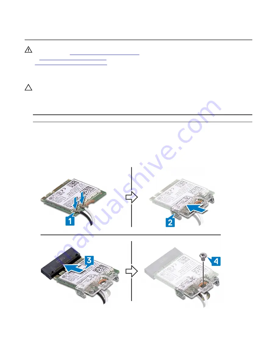
CAUTION: To avoid damage to the wireless card, do not place any cables under it.
1
Connect the antenna cables to the wireless card.
The following table provides the antenna-cable color scheme for the wireless card that is supported by your computer.
Table 2. Antenna-cable color scheme
Connectors on the wireless card
Antenna-cable color
Main (white triangle)
White
Auxiliary (black triangle)
Black
2 Slide and replace the wireless-card bracket on the wireless-card.
3 Align the notch on the wireless card with the tab on the wireless-card slot and insert the wireless card at an angle into the
wireless-card slot.
4 Replace the screw (M2x3) that secures the wireless-card bracket to the system board.
27
Содержание Alienware Area-51m
Страница 18: ...3 Tighten the six captive screws that secure the base cover to the computer base 18 ...
Страница 20: ...3 Lift the battery off the palm rest assembly 20 ...
Страница 23: ...3 Remove the memory module from the memory module slot 23 ...
Страница 26: ...5 Disconnect the antenna cables from the wireless card 26 ...
Страница 28: ...Post requisites Replace the base cover 28 ...
Страница 38: ...Post requisites Replace the base cover 38 ...
Страница 45: ...4 Replace the base cover 45 ...
Страница 49: ...6 Lift the touchpad off the palm rest assembly 49 ...
Страница 54: ...12 Lift the display assembly off the palm rest assembly 54 ...
Страница 59: ...13 Lift the computer base off the palm rest assembly 59 ...
Страница 63: ...4 Lift the heat sink assembly off the system board 63 ...
Страница 68: ...7 Replace the base cover 68 ...
Страница 70: ...4 Lift the processor straight up to remove it from the system board 70 ...
Страница 73: ...5 Lift the graphics card off the system board 73 ...
Страница 75: ...6 Replace the battery 7 Replace the base cover 75 ...
Страница 78: ...11 Remove the left power adapter port 78 ...
Страница 79: ...12 After performing all the above steps you are left with the system board 79 ...
Страница 84: ...84 ...
Страница 86: ...10 Replace the battery 11 Replace the base cover 86 ...
Страница 89: ...8 Lift the keyboard from bottom and slide out of the clips at top 89 ...
Страница 93: ...93 ...
Страница 95: ...11 Replace the battery 12 Replace the base cover 95 ...
Страница 97: ...97 ...