Troubleshooting Notes
EMC VNXe3100/VNXe3150 — Adding a Second Storage Processor
13
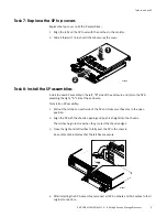
9. Reinstall SP A.
10. Reinstall SP B.
11. Reconnect all cables that were removed.
12. Reconnect the power cables to both SPs.
13. Continue with
“Task 11: Validate the upgrade and reboot the system” on page 10
.
Problem: You believe that you have a hardware problem, and want to abort the upgrade in
progress.
Solution: In the unlikely event that bad/damaged upgrade components were received and
your attempt to validate the upgrade failed, the upgrade may be aborted. You will need to
remove the parts that were added earlier in this procedure.
Note:
Review
your
decision
to
abort
the
upgrade
procedure
with
your
service
provider
.
1. From the service console in service mode, run command svc_change_config --abort.
It displays a message to restore the hardware to the previous configuration.
2. Wait for the prompt to return to the console window, which indicates that the service
script completed.
3. Release the cable retention bail and unplug the power cord from each power supply
(both SPs and any attached DAEs); and, label and remove all cables from both SPs.
4. Locate the two orange release levers on SP B latches.
5. Squeeze the levers to release the latches and then pull the latches outward.
6. Pull out the latches until they are fully extended and the SP B is released from its
enclosure.
7. Use the latches to partially slide SP B from its enclosure.
8. When SP B is about halfway out of its enclosure, use both hands to support SP B and
draw it fully out of the enclosure.
9. Place the SP B on a clean, flat, static-free work surface.
10. Return the cache protection module to slot B.
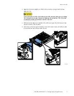
11. Locate the two orange release levers on the SP A latches.
12. Squeeze the levers to release the latches and then pull the latches outward.
13. Pull out the latches until they are fully extended and SP A is released from its
enclosure.
14. Use the latches to partially slide SPA from its enclosure.
15. When SP A is about halfway out of its enclosure, use both hands to support SP A and
draw it fully out of the enclosure.
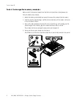
Remove the new memory DIMMs placed in the DIMM slots on SP A and insert the
original memory DIMMs. Refer to
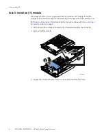
“Task 6: Exchange the memory modules” on page 8
.
16. Reconnect the power cables that were removed from any DAEs.
17. Reconnect all cables to SP A, including the power cable.


