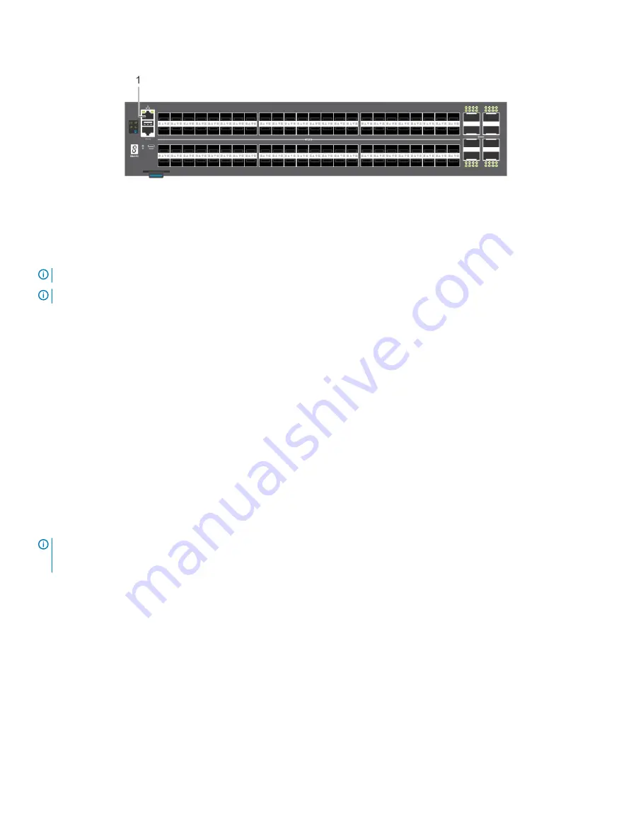
Figure 30. S5296F-ON switch management ports
1
Out-of-band management port (top); RS-232 console port
(bottom)
NOTE:
Ensure that any equipment that is attached to the serial port can support the required 115200 baud rate.
NOTE:
If the serial port on your computer cannot accept a female DB-9 connector, use a DB-9 to USB adaptor.
1
Install the provided RJ-45 connector-side of the provided cable into the switch console port.
2
Install the DB-9 female-side of the provided copper cable into the serial port on your computer.
Or install the DB-9 cable into other data terminal equipment (DTE) server hardware.
3
Use the following settings to make the serial port connection:
•
115200 baud rate
•
No parity
•
Eight data bits
•
One stop bit
•
No flow control
MicroUSB-B console port access
The MicroUSB-B console port is on the I/O side of the S5200F-ON Series switch.
When you connect the microUSB-B port, it becomes the primary connection and, while connected, all messages are sent to the microUSB-
B port.
NOTE:
Before starting this procedure, be sure that you have a terminal emulation program already installed on your PC. Install
the appropriate drivers to support the microUSB-B port. To download Dell EMC drivers, see
. If your
computer requires non-Dell EMC drivers, contact Dell EMC Technical Support for assistance.
1
Power on the PC.
2
Connect the USB-A end of cable into an available USB port on the PC.
3
Connect the microUSB-B end of cable into the microUSB-B console port on the switch.
4
Power on the switch.
5
Install the necessary USB device drivers.
To download Dell EMC drivers, see
. If your computer requires non-Dell EMC drivers, contact Dell EMC
Technical Support for assistance.
6
Open your terminal software emulation program to access the switch.
7
Confirm that the terminal settings on your terminal software emulation program are as follows:
•
115200 baud rate
•
No parity
•
8 data bits
46
Management ports


