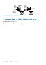
Two PowerMax 2000 systems - 1 Powe 2
PowerBrick configuration
Engine 1
DAE 1
DAE 2
SPS
SPS
20U
Engine 1
DAE 1
DAE 2
SPS
SPS
Engine 2
DAE 3
DAE 4
SPS
SPS
U10
U21
A
B
C
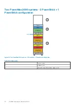
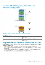
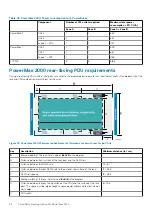
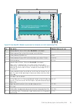
Figure 21. Two PowerMax 2000 systems - 1 Powe 2 PowerBrick configuration
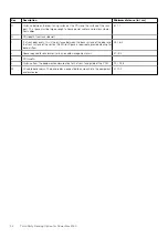
Table 33. Stack up key
A
Lower system
B
Space for second PowerBrick, lower system
C
Upper system
Requirements for customer components in a rack
Customer components can coexist in a rack with a PowerMax 2000 system. The system must be properly positioned within the rack in
accordance with the following rules:
•
Dell EMC equipment should stack from the bottom of the rack. Customer equipment stacks from the top of the rack.
•
A system must exist within contiguous space. Customer equipment must be above a PowerMax 2000 system and not interwoven
within the system.
•
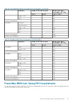
All customer equipment must be electrically isolated and powered by the upper half of the PDUs and powered by separate power
cords. The power cord pairs listed in
on page 37 are available as optional models.
•
Racks with two PowerMax 2000 systems cannot have customer components installed in the rack.
Dell EMC Racking for PowerMax 2000
49


