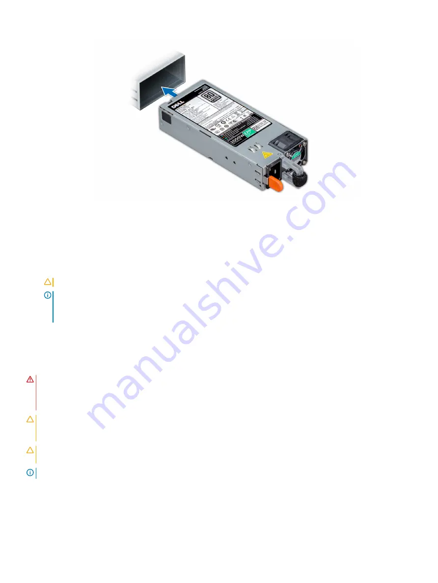
Figure 130. Installing a power supply unit
Next steps
1
If you have unlatched the cable management arm, relatch it. For information about the cable management arm, see the system’s rack
documentation at
.
2
Connect the power cable to the PSU, and plug the cable into a power outlet.
CAUTION:
When connecting the power cable to the PSU, secure the cable to the PSU with the strap.
NOTE:
When installing, hot swapping, or hot adding a new PSU, wait for 15 seconds for the system to recognize the PSU
and determine its status. The PSU redundancy may not occur until discovery is complete. Wait until the new PSU is
discovered and enabled before you remove the other PSU. The PSU status indicator turns green to signify that the PSU is
functioning properly.
Wiring instructions for a DC power supply unit
Your system supports up to two –(48–60) V DC power supply units (PSUs).
WARNING:
For equipment using –(48–60) V DC power supply units (PSUs), a qualified electrician must perform all connections
to DC power and to safety grounds. Do not attempt connecting to DC power or installing grounds yourself. All electrical wiring
must comply with applicable local or national codes and practices. Damage due to servicing that is not authorized by Dell is not
covered by your warranty. Read and follow all safety instructions that came with the product.
CAUTION:
Wire the unit with copper only, unless otherwise specified, use only 10 American Wire Gauge (AWG) wire rated
minimum 90ºC for source and return. Protect the –(48–60) V DC (1 wire) with a branch circuit over-current protection rated 50
A for DC with a high interrupt current rating.
CAUTION:
Connect the equipment to a –(48–60) V DC supply source that is electrically isolated from the AC source (reliably
grounded –(48–60) V DC SELV source). Ensure that the –(48–60) V DC source is efficiently secured to earth (ground).
NOTE:
A readily accessible disconnect device that is suitably approved and rated shall be incorporated in the field wiring.
Input requirements
•
Supply voltage: –(48–60) V DC
Installing and removing system components
173
Содержание PowerEdge R740
Страница 9: ...Figure 1 Supported configurations PowerEdge R740 system overview 9 ...
Страница 27: ...Figure 20 Jumper setting and memory information Figure 21 system task PowerEdge R740 system overview 27 ...
Страница 28: ...Figure 22 NVDIMM battery and mid tray hard drives 28 PowerEdge R740 system overview ...
Страница 141: ...Figure 94 Securing GPU 1 Installing and removing system components 141 ...
Страница 142: ...Figure 95 Installing GPU 2 and 3 142 Installing and removing system components ...


