


5
In the
Add Uplink
window, complete the following steps:
a Enter the name in the
Name
box.
b Enter the description in the
Description
box.
c From the
Uplink Type
list, select
Ethernet
.
d Click
Next
.
e From the
Switch Ports
list, select the appropriate Ethernet ports:
1
Ethernet 1/1/11 from both MX5108n IOMs
2
Ethernet 1/1/41 and Ethernet 1/1/42 from both MX9116n IOMs
f
From the
Tagged Networks
list, select all four
Cloud Foundation VLANs
.
g From the
Untagged Network
list, select any required untagged VLAN.
h Click
Finish
.
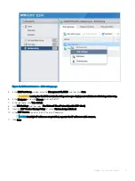
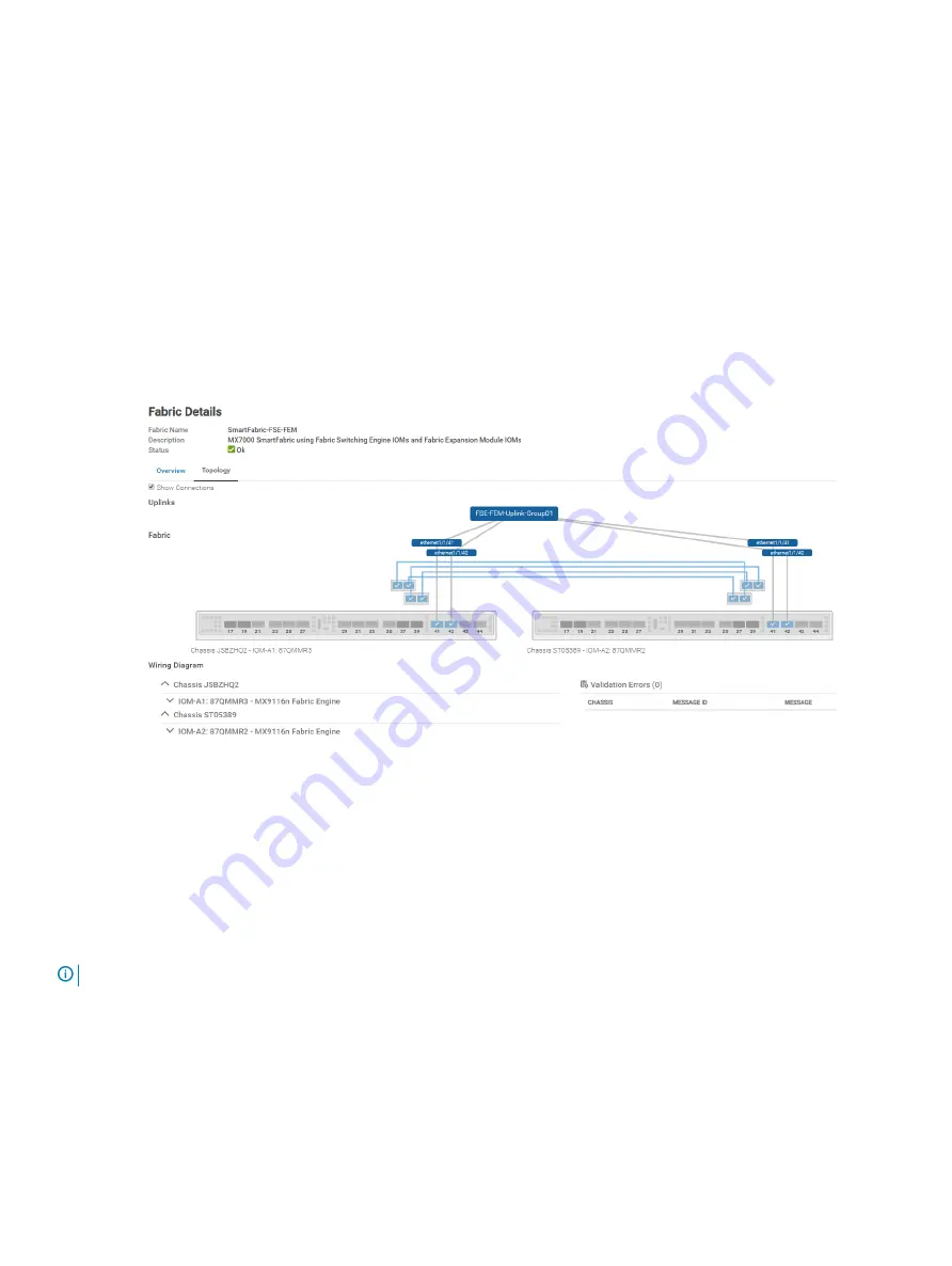
6
To verify the switch topology, from the
Devices
menu, click
Fabric
, and then perform the following steps:
a Click the fabric that was created.
b Click
Topology
.
The selected topology image is displayed as shown in the following figure:
Figure 34. Topology of the SmartFabric using MX9116n Fabric Switching Engine IOMs
SmartFabric creates the uplink object and the status for the fabric changes to
OK
.
Configure jumbo frames
About this task
Cloud Foundation requires jumbo frames on all links.
NOTE:
By default, SmartFabric does not configure the jumbo MTU (frame size) on switch ports.
To configure jumbo frames, set the MTU (frame size) using the following procedure:
Steps
1
From the
Devices
menu, click
I/O Modules
.
2
Select the
IO Module
.
3
From the
IOM banner
menu, click
Hardware
.
4
Click
Port Information
.
SmartFabric network configuration
59
Содержание PowerEdge MX7000
Страница 1: ...Dell EMC VMware Cloud Foundation for PowerEdge MX7000 Deployment Guide ...
Страница 8: ...Figure 1 Cloud Foundation deployment workflow 8 Overview ...
Страница 27: ...Figure 19 Dual PowerEdge MX7000 enclosure configuration Physical layout 27 ...
Страница 29: ...Figure 20 MX9002m Management module cabling Physical layout 29 ...
Страница 30: ...Figure 21 Connectivity between FSE modules and FEM modules 30 Physical layout ...
Страница 31: ...Figure 22 Uplinks to customer network environment Physical layout 31 ...
Страница 42: ...Figure 25 MX9002m Management Module cabling 42 Networking requirements ...
Страница 43: ...Figure 26 Connectivity between FSE modules and FEM modules Networking requirements 43 ...
Страница 44: ...Figure 27 Uplinks to customer network environment 44 Networking requirements ...