


Figure 18. Single PowerEdge MX7000 enclosure configuration
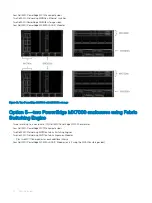
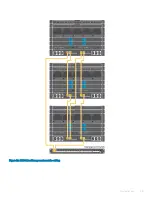
Cabling for a dual MX7000 enclosure configuration
The following figure shows the external cabling for a multiple PowerEdge MX7000 enclosure configuration. The Customer Network Link
Aggregation is shown as an example as the upper layer connection is not specified except that it must use an LACP enabled Link
Aggregation (LAG). You can add more enclosures that connect back to the upper level devices in the infrastructure.
26
Physical layout
Содержание PowerEdge MX7000
Страница 1: ...Dell EMC VMware Cloud Foundation for PowerEdge MX7000 Deployment Guide ...
Страница 8: ...Figure 1 Cloud Foundation deployment workflow 8 Overview ...
Страница 27: ...Figure 19 Dual PowerEdge MX7000 enclosure configuration Physical layout 27 ...
Страница 29: ...Figure 20 MX9002m Management module cabling Physical layout 29 ...
Страница 30: ...Figure 21 Connectivity between FSE modules and FEM modules 30 Physical layout ...
Страница 31: ...Figure 22 Uplinks to customer network environment Physical layout 31 ...
Страница 42: ...Figure 25 MX9002m Management Module cabling 42 Networking requirements ...
Страница 43: ...Figure 26 Connectivity between FSE modules and FEM modules Networking requirements 43 ...
Страница 44: ...Figure 27 Uplinks to customer network environment 44 Networking requirements ...


