background image

The PWM output (0 to 100 %) is configured as a curve, in the same way as the other analogue outputs.

More information

See 

Hardware characteristics and configuration

General characteristics

Analogue output characteristics and

configuration

.

Duty cycles

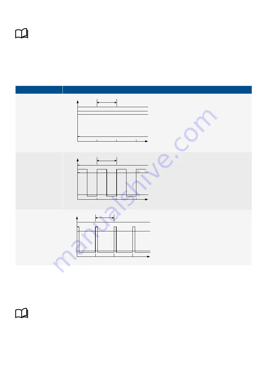
The PWM uses duty cycles for its output. The PWM frequency determines the cycle length. One cycle is therefore 1/500 Hz = 0.002
seconds long, ±10 %. The following table illustrates the output for various duty cycles.

Table 13.38

Relationship between duty cycles and the PWM output

Duty cycle

Graph

100 % 

Cycle

0

Voltage

[V]

time [s]

6.85

0.5

0.002

0.004

5.5

50 % 

0

Voltage

[V]

time [s]

0.5

0.002

0.004

5.5

Cycle

6.85

12.5 % 

0

5.5

Voltage

[V]

time [s]

0.5

0.002

0.004

0.006

Cycle

6.85

13.10.5 Analogue input (AI) characteristics

This analogue input can be configured as either current (0 to 24 mA) or voltage (-10 to 10 V). Using a configured or selected input
curve, the controller converts the input to a corresponding value. You can also configure the input to activate functions and/or
alarms.

More information

See 

Hardware characteristics and configuration

General characteristics

Analogue input characteristics and

configuration

.

Galvanic connection

The two analogue inputs on GAM3.1 are galvanically connected. You therefore cannot use the analogue inputs on GAM3.1 in series
with each other (for example, for a back-up measurement).

DESIGNER'S HANDBOOK 4189340911K UK 

Page 455 of 521

Содержание PPM 300

Страница 1: ...DESIGNER S HANDBOOK Protection and Power Management PPM 300 DEIF A S Frisenborgvej 33 DK 7800 Skive Tel 45 9614 9614 Fax 45 9614 9615 info deif com www deif com Document no 4189340911K ...

Страница 2: ...nually override active alarm actions 23 1 2 10 Do not use unsupported hardware modules 23 1 2 11 Data security 23 1 3 Legal information 24 1 3 1 Third party equipment 24 1 3 2 Warranty 24 1 3 3 Open source software 24 1 3 4 Trademarks 24 1 3 5 Copyright 24 1 3 6 Disclaimer 24 2 System principles 2 1 Description 25 2 1 1 Overall description 25 2 1 2 Controller types 26 2 2 Overall system 26 2 2 1 I...

Страница 3: ...ce voltage ANSI 59Uo 65 3 4 7 Over current ANSI 50TD 66 3 4 8 Fast over current ANSI 50 50TD 66 3 4 9 Current unbalance ANSI 46 67 3 4 10 Directional over current ANSI 67 68 3 4 11 Inverse time over current ANSI 51 68 3 4 12 Negative sequence current ANSI 46 72 3 4 13 Zero sequence current ANSI 51Io 73 3 4 14 Source over frequency ANSI 81O 74 3 4 15 Source under frequency ANSI 81U 74 3 4 16 Overlo...

Страница 4: ... level 100 4 2 9 Auto acknowledge 101 4 2 10 Latch 101 4 2 11 Suppress action parameter 101 4 2 12 Alarm test 101 4 2 13 Additional alarm information 102 4 3 Customised inhibits 102 4 3 1 Configuring customised inhibits 102 4 3 2 Suppress action inhibit 103 4 4 Alarm handling 103 4 4 1 Overview of alarm handling 103 4 4 2 Acknowledge 105 4 4 3 Shelve 106 4 4 4 Out of service 107 4 4 5 Latch reset ...

Страница 5: ...Q load sharing failure high voltage on DG 135 4 10 7 Overload on DG 135 4 10 8 Reverse power on DG 136 4 10 9 Reactive power export on DG 136 4 10 10 Reactive power import on DG 137 4 10 11 Over current on DG 137 5 Breakers synchronisation and de loading 5 1 Introduction 139 5 1 1 Introduction to synchronisation and de loading 139 5 1 2 Regulation required for synchronisation 139 5 1 3 Regulation ...

Страница 6: ...uency regulation 175 6 2 3 Frequency synchronisation 176 6 2 4 Phase synchronisation 176 6 2 5 Power regulation 176 6 2 6 Power load sharing 177 6 2 7 Governor stand alone mode 178 6 3 AVR regulation modes 180 6 3 1 Overview 180 6 3 2 Voltage regulation 180 6 3 3 Reactive power regulation 181 6 3 4 Reactive power load sharing 182 6 3 5 AVR stand alone mode 183 6 4 External communication 185 6 4 1 ...

Страница 7: ...reservation 220 7 2 3 Power analogue outputs 221 7 3 Genset priority 222 7 3 1 Genset start and stop priority order 222 7 3 2 Priority selection method 223 7 3 3 Manual genset priority 223 7 3 4 Dynamic genset priority 224 7 3 5 Running hours for genset priority 225 7 3 6 Genset priority digital outputs 226 7 4 Genset start and stop 227 7 4 1 Introduction 227 7 4 2 Load dependent start configurati...

Страница 8: ...ion mismatch 274 7 9 3 Heavy consumer reservation not possible 274 7 9 4 Heavy consumer feedback timeout 275 7 9 5 Missing all controllers 275 7 9 6 Missing controller ID 276 7 9 7 Duplicate controller ID 276 7 9 8 Missing any controller 276 7 9 9 Missing controllers 276 7 9 10 Forced to switchboard control 277 7 9 11 Forced to SEMI mode 277 7 9 12 DEIF network redundancy broken 278 7 9 13 Single ...

Страница 9: ...en flowchart 302 8 5 5 Generator breaker trip flowchart 303 8 6 Other GENSET controller functions 304 8 6 1 Temperature controlled start stop 304 8 6 2 Priming 304 8 6 3 Temperature dependent power derating 305 8 6 4 Engine operating values as analogue outputs 306 8 6 5 Engine states as digital outputs 306 8 6 6 Counters 307 8 6 7 Trip AVR 308 8 7 GENSET controller alarms 308 8 7 1 GENSET controll...

Страница 10: ...tion 326 9 5 Emergency genset breakers 326 9 5 1 Introduction 326 9 5 2 EMERGENCY genset controller breaker parameters 326 9 5 3 Generator breaker close flowchart 327 9 5 4 Generator breaker open flowchart 328 9 5 5 Generator breaker trip flowchart 329 9 5 6 Tie breaker close flowchart 329 9 5 7 Tie breaker open flowchart 330 9 5 8 Tie breaker trip flowchart 331 9 6 Emergency genset test functions...

Страница 11: ... line diagram 354 10 2 2 Nominal settings 355 10 2 3 Power management 355 10 2 4 Running detection 355 10 2 5 AC configuration 356 10 2 6 Breaker configuration 356 10 3 Shaft generator breaker 356 10 3 1 Introduction 356 10 3 2 Shaft generator breaker close flowchart 356 10 3 3 Shaft generator breaker open flowchart 358 10 3 4 Shaft generator breaker blackout close flowchart 359 10 3 5 Shaft gener...

Страница 12: ...3 11 3 4 Shore connection breaker blackout close flowchart 385 11 3 5 Shore connection breaker trip flowchart 386 11 4 Other SHORE connection controller functions 387 11 4 1 Ship to ship 387 11 4 2 Shore connection base load 390 11 4 3 Minimum load to close shore connection 390 11 4 4 Connect multiple shore connections 390 11 4 5 Sensitive shore connection overlap 392 11 4 6 Shore connection load ...

Страница 13: ...nput characteristics and configuration 417 13 2 5 Analogue input characteristics and configuration 418 13 2 6 Analogue output characteristics and configuration 421 13 3 Power supply module PSM3 1 423 13 3 1 Power supply module PSM3 1 423 13 3 2 PSM3 1 terminal overview 424 13 3 3 Frame ground characteristics 425 13 3 4 Power supply characteristics 425 13 3 5 PSM3 1 1 supply voltage low alarm 425 1...

Страница 14: ... alarm 447 13 9 6 EIM3 1 1 supply voltage high alarm 447 13 9 7 Auxiliary power supply voltage as an analogue output 448 13 9 8 Digital input characteristics 448 13 9 9 Magnetic pickup unit MPU input characteristics 448 13 9 10 W input characteristics 449 13 9 11 Magnetic pickup wire break 450 13 9 12 Analogue input AI characteristics 450 13 9 13 Relay output characteristics 451 13 9 14 Relay outp...

Страница 15: ...Communication 470 13 14 2 Communication information 471 13 14 3 Restrictions 472 13 15 DEIF internal communication 472 13 15 1 Internal communication 472 13 15 2 Fieldbus conflict 473 13 15 3 Fieldbus connection missing 473 14 PICUS 14 1 Overview 474 14 1 1 Using PICUS 474 14 1 2 Configuration update delayed 474 15 CustomLogic 15 1 Overview 475 15 1 1 Using CustomLogic 475 15 1 2 CustomLogic input...

Страница 16: ...e time manually 486 18 1 3 Using an external NTP server 486 18 1 4 NTP server not connected 486 18 1 5 NTP server no response 486 18 2 Permissions 487 18 2 1 Introduction 487 18 2 2 Group settings 489 18 2 3 User settings 490 18 2 4 Default users 491 18 2 5 Default group permissions 491 18 3 Log 495 18 3 1 Overview 495 18 4 Miscellaneous 496 18 4 1 Lamp test 496 18 4 2 Alive 497 18 5 Change contro...

Страница 17: ...high 515 20 4 3 Pt100 516 20 4 4 Pt1000 517 20 4 5 VDO 40 120 518 20 4 6 VDO 50 150 518 20 4 7 VDO temperature CU 519 20 5 Analogue output 100 to 100 curves 519 20 5 1 100 to 100 to 25 to 25 mA 519 20 5 2 100 to 100 to 0 to 20 mA 519 20 5 3 100 to 100 to 4 to 20 mA 519 20 5 4 100 to 100 to 10 to 10 V 520 20 5 5 100 to 100 to 0 to 10 V 520 20 5 6 100 to 100 to 0 to 100 520 20 6 Analogue output 0 to...

Страница 18: ...rotections and functions The Designer s handbook can also be used during commissioning to check the design drawings and the controller parameters Operators may find the Designer s handbook useful for understanding the system and for troubleshooting 1 1 3 Symbols and conventions in the Designer s handbook Controller symbols These symbols show the relevant controller types for a description Controll...

Страница 19: ... hardware module Breaker represents the Generator breaker for a GENSET controller More information See System principles Overall principles General names for controller types for more information Numbered possibilities The hash symbol is used when there are several numbered possibilities to avoid repeating the same function description for each numbered possibility Use of hash example Controller I...

Страница 20: ... controller under Configure Input output assign the required input or output function s to each set of terminals d For each controller under Configure Parameters configure the parameters e Optional For each controller under Configure CustomLogic create additional functions if required f Under Configure Emulation use emulation to test the system operation Emulation is a controller test environment ...

Страница 21: ...ciples Busbar sections and load sharing AC configuration and nominal settings Protections and alarms Regulation Breakers synchronisation and de loading Power management Controller types Hardware characteristics and configuration PICUS CustomLogic Emulation Modbus See the Modbus tables for the Modbus address associations Installation instructions Tools and materials Mounting Default wiring for the ...

Страница 22: ...ches when it is off The controller does not provide any control or power management All the controller relays de energise 1 2 3 Connect the controller protective earth You must ground the controller rack to create a protective earth DANGER Failure to ground the controller rack could lead to injury or death 1 2 4 Switchboard control Under Switchboard control the operator controls and operates the e...

Страница 23: ...not manually override active alarm actions DANGER Do not use switchboard or manual control to override the alarm action of an active alarm An alarm may be active because it is latched or because the alarm condition is still present If the alarm action is manually overridden a latched alarm does not do its alarm action again In this situation the latched alarm does not provide protection Latched Ov...

Страница 24: ... Trademarks DEIF is a trademark of DEIF A S Bonjour is a registered trademark of Apple Inc in the United States and other countries CANopen is a registered community trademark of CAN in Automation e V CiA CODESYS is a trademark of 3S Smart Software Solutions GmbH EtherCAT is a registered trademark and patented technology licenced by Beckhoff Automation GmbH Germany Modbus is a registered trademark...

Страница 25: ...controller functions as a master controller If a controller fails the remaining controllers continue to function Redundant communication between the controllers is possible If a communication link fails the system continues to function The controller display unit has push buttons for the operator to close and open the breaker For gensets the operator can start and stop the genset and change the co...

Страница 26: ...tem provides power management protection and supervision functions The power management system calculates the control set points although some of these can also come from third party equipment external set points The power management system automatically starts and stops engines and closes and opens breakers The operator or another external source can also initiate these actions 2 2 2 Control and ...

Страница 27: ...the genset CustomLogic activates an external command function SEMI External A function is programmed in CustomLogic The CustomLogic rung has the conditions that need to be met There is a Normally open coil with the function Engine Command Start engine at the end of the rung The conditions are met and CustomLogic activates the function The controller detects that the function is activated and start...

Страница 28: ...ustomLogic or an external system using a Modbus command can initiate the generator breaker close Similarly the generator excitation can be controlled using an analogue output or digital outputs Finally the DEIF network allows information from all the controllers to be used by any of the controllers For example for power management the analogue and digital inputs and outputs for a heavy consumer ca...

Страница 29: ...nalogue and digital outputs The controller can send analogue and digital outputs to the genset breakers a PLC the switchboard for example for lights and meters and other equipment for example heavy consumers A wide variety of purposes including control status and alarm indicators and as input to a PLC 4 Analogue or digital outputs for governor control The controller can control the genset governor...

Страница 30: ... These restrictions also apply Types Possible Notes GENSET controller 1 to 32 There must be at least one GENSET controller EMERGENCY genset controller 0 to 1 SHAFT generator controller 0 to 31 See Restrictions too SHORE connection controller 0 to 31 See Restrictions too BUS TIE breaker controller 0 to 31 2 2 5 Restrictions PPM 300 is not suitable for all possible marine configurations Some configu...

Страница 31: ...ce 4 For continuous functions a If the function is assigned to hardware If Modbus sends a command then the command is not allowed and has no effect b If the function is not assigned to hardware If Modbus and CustomLogic send conflicting signals then the controller uses the CustomLogic signal INFO Commands from display unit push buttons have the same priority as wiring connected to hardware Analogu...

Страница 32: ... switch on the switchboard from a PLC or from CustomLogic The controller remains under switchboard control until the digital input is turned off A controller is unpowered if it loses its power supply Detailed descriptions of each control type and mode follow below 2 3 2 Power management system control All of the controllers normally run under PMS control The power management system is enabled and ...

Страница 33: ...d control Digital output Continuous Activated if the controller is under Switchboard control INFO If you want to automatically activate Switchboard control when the digital input is deactivated use the PMS control digital input Table 2 5 Optional inputs for manual governor regulation Function I O Type Details Regulators GOV Manual Manual GOV increase Digital input Continuous This input only has an...

Страница 34: ... AVR output analogue output Set the percentage change of the AVR voltage per second under Configure Parameters Regulators AVR analogue configuration Manual slope Regulators AVR Command Reset AVR to offset Digital input Pulse This input only has an effect when the regulator uses the analogue output for regulation When this input is activated the controller resets the AVR output to the offset This c...

Страница 35: ...chboard control the controller mode is semi automatic SEMI AUTO mode After Switchboard control the controller mode is automatic AUTO Events that force controllers under switchboard control The following events force all the controllers in the section to operate under Switchboard control The Power management Force all controllers in section to SWBD control command or digital input on ANY controller...

Страница 36: ...ated alarm action For example if an alarm with an alarm action Trip generator breaker and shutdown engine is activated while the controller is under Switchboard control then the controller trips the breaker and shuts down the engine Alarm actions under switchboard control example For a GENSET controller you can create a low lube oil pressure alarm based on an analogue input from a sensor that has ...

Страница 37: ... no effect on the other controllers INFO There can be a blackout while a connected controller is under Switchboard control For the GENSET EMERGENCY genset SHAFT generator and SHORE connection controllers for the default under voltage settings the breaker will trip 2 3 4 Automatic AUTO mode Controller types Only GENSET and EMERGENCY genset controllers In AUTO mode the GENSET controllers automatical...

Страница 38: ...n SEMI mode If local measurements show that the genset is overloaded then the NEL s trip to protect the power supply to the main busbar Input Configure the input under Configure Input output Select the hardware module then select the input to configure Function I O Type Details Mode SEMI mode Digital input Pulse If it is possible the controller is put into SEMI mode when this input is activated Th...

Страница 39: ...ystem s controllers is unpowered Missing controller ID Missing any controller Effect of the unpowered controller hardware DEIF network links through the unpowered controller are broken If a redundant DEIF network link is not available the controllers on either side of the unpowered controller cannot communicate with each other If a redundant DEIF network link is available then the controllers on e...

Страница 40: ...s commands to 3rd party equipment operating information Analogue input functions External set points operating information supervised binary inputs Analogue output functions Regulation operating information Up to 4 sets of nominal settings Select a different set of nominal settings at any time Configurable parameters for controller functions Several ways to start controller sequences Automatically...

Страница 41: ...connects to loads inputs and failure scenarios Test the application get approvals minimise site time optimise training System supervision Manage controller and display unit software Supports multiple controller languages CustomLogic User friendly logic configuration tool based on ladder logic and function blocks Up to 20 selectable input events and 20 output commands per controller Inter controlle...

Страница 42: ...er position detection and alarms Advanced blackout prevention optional Run with a closed bus tie breaker during critical operations If a genset governor or AVR fails the bus tie breaker trips and disconnects the genset Redundancy True multi master control Busbar can have a ring connection DEIF network ring connection Internal communication ring connection Controller commands and operation using th...

Страница 43: ...Functions Modbus table Context sensitive help in the display unit Note Only for the GENSET and EMERGENCY genset controllers DESIGNER S HANDBOOK 4189340911K UK Page 43 of 521 ...

Страница 44: ... single phase in the USA Split phase L2 L3 The waveforms are offset by a half cycle 180 degrees from the neutral wire This is sometimes called single phase in the USA Single phase L1 The generator and busbar are single phase Use the L1 terminal for the voltage and current measurements not the L2 or L3 terminals The current measurement on the neutral phase N is optional Single phase L2 The generato...

Страница 45: ... for examples controller functions AC measurement wiring System AC configuration in the Installation instructions for an example of wiring required for the phase to neutral voltage measurements INFO This parameter does not affect the nominal voltages The nominal voltages are always phase to phase voltages Phase direction AC phase rotation Configure this parameter under Configure Parameters Source ...

Страница 46: ...Busbar A Busbar B 3 1 3 Source AC configuration You can configure the source s AC configuration under Configure Parameters Source AC setup Voltage transformer These parameters relate to the terminals on the ACM3 1 Configure these parameters under Configure Parameters Source AC setup Voltage transformer You must set these parameters if there is a voltage transformer on the source s voltage measurem...

Страница 47: ...nly apply to the current measurements on L1 L2 and L3 More information See the Installation instructions Default wiring for controller types ACM3 1 terminal connections and default wiring for examples of generator current transformer wiring Parameter Range Default Notes Primary 5 to 9000 A 1000 A The current transformer primary side source side nominal current Secondary 1 or 5 A 1 A The current tr...

Страница 48: ... parameters to calculate whether the voltage and frequency from the source measurements are OK so that the breaker can close Parameter Range Default Notes Voltage and frequency OK 0 s to 1 h 2 s If the voltage and frequency are OK for this time in seconds then the equipment s LED becomes steady green The breaker is not allowed to close before the LED is steady green that is not flashing Minimum OK...

Страница 49: ...igure these parameters under Configure Parameters Busbar AC setup Voltage transformer You must set these parameters if there are voltage transformers on the busbar voltage measurement If Primary Secondary ratio is 1 the controller uses the voltage measurement without any correction for a voltage transformer The controller does not need information about the voltage transformer type for example ope...

Страница 50: ...out close 3 1 5 Voltage and frequency as digital outputs For the Source and the Busbar you can configure digital outputs with functions for Voltage and frequency OK and No voltage and frequency These functions are based on the AC measurements and parameters and can be useful for troubleshooting Outputs Assign the function to a digital output under Configure Input output Select a hardware module wi...

Страница 51: ...unctions These include power management and protections Many protection settings are based on a percentage of the nominal settings Each controller can store four sets of nominal settings You can easily change the active set of nominal settings by changing the parameter using a digital input analogue input or an external source for example Modbus INFO Always check that the conditions are safe to ch...

Страница 52: ...ontroller nominal setting Nominal setting selected Digital output Continuous Activated if the active nominal setting group is the same as the nominal setting group configured to the output Local Nominal settings Controller nominal setting Nominal setting Analogue input Supervised binary input The controller changes the active nominal setting group to the nominal setting group assigned to the analo...

Страница 53: ...arameters Power management rules Configuration Nominal settings Controller nominal setting where is 1 to 8 Table 3 3 Power management nominal setting parameter Parameter Range Default Notes Selection Nominal setting 1 Nominal setting 2 Nominal setting 3 Nominal setting 4 Nominal setting 1 The selected nominal setting group for the controller when the Source parameter Local Nominal settings Control...

Страница 54: ...ted from the AC measurements The controller then adjusts the analogue output to reflect the AC operating value Applications An analogue output with a function for an alternating current AC operating value may be wired to a switchboard instrument to help the operator For example the total kW from a generator can be displayed Alternatively an analogue output may be wired to a switchboard instrument ...

Страница 55: ...he lowest L N voltage Source Voltage V Equipment L N max V AC The controller outputs the highest L N voltage that is for the phase with the highest L N voltage Source Voltage V Equipment L N unbalanced V AC The controller outputs the L N unbalanced voltage from the source relative to the zero of the star point Source Voltage V Equipment L L min V AC The controller outputs the lowest L L voltage th...

Страница 56: ...equence A The controller outputs the magnitude of the negative sequence current Source Current I Equipment Zero sequence A The controller outputs the magnitude of the zero sequence current from the source Source Current I Equipment Min A The controller outputs the lowest phase current Source Current I Equipment Max A The controller outputs the highest phase current Source Current I Equipment Unbal...

Страница 57: ...ent L2 restraint A The controller outputs the L2 restraint current Source Current I ACM3 2 Equipment L3 restraint A The controller outputs the L3 restraint current Source Current I ACM3 2 Equipment Min restraint A The controller outputs the lowest phase restraint current Source Current I ACM3 2 Equipment Max restraint A The controller outputs the highest phase restraint current Source Current I AC...

Страница 58: ...nctions Function Details Source Apparent power S Equipment L1 kVA The controller outputs the L1 apparent power Source Apparent power S Equipment L2 kVA The controller outputs the L2 apparent power Source Apparent power S Equipment L3 kVA The controller outputs the L3 apparent power Source Apparent power S Equipment Total kVA The controller outputs the total apparent power Source Apparent power S E...

Страница 59: ...names follow these formats Busbar Physical quantity Equipment Measurement unit For example Busbar A Apparent power S Busbar A Total kVA Table 3 16 Busbar AC measurement function names for each controller type Controller type Busbar Equipment GENSET Busbar Busbar EMERGENCY genset Busbar Busbar SHAFT generator Busbar Busbar SHORE connection Ship busbar Busbar BUS TIE breaker Busbar B Busbar B Table ...

Страница 60: ...asurement Busbar Frequency f Equipment L2 Hz The controller outputs the L2 frequency based on the voltage measurement Busbar Frequency f Equipment L3 Hz The controller outputs the L3 frequency based on the voltage measurement Busbar Frequency f Equipment Min Hz The controller outputs the frequency of the phase with the lowest frequency based on the voltage measurement Busbar Frequency f Equipment ...

Страница 61: ... measurement and the Busbar voltage Table 3 25 4th current input power factor analogue output functions Function Details Local 4th current input Power factor PF L4 cos phi The controller outputs the power factor calculated as cos phi based on the 4th current measurement and the Busbar voltage Local 4th current input Power factor PF L4 Power factor The controller outputs the power factor based on t...

Страница 62: ...ymbol IEC60617 ANSI IEEE C37 2 IEC 61850 Operate time Over voltage U U 59 PTOV 100 ms The alarm response is based on the highest phase to phase voltage or the highest phase to neutral voltage from the source as measured by the controller The phase to phase voltage is the default Set point Value time Delay Configure the parameters under Configure Parameters Source Voltage protections Over voltage w...

Страница 63: ... point 50 to 100 of nominal voltage 95 80 Delay 0 00 s to 1 h 5 00 s 3 00 s Enable Not enabled Enabled Enabled Enabled Latch Not enabled Enabled Not enabled Enabled Action Warning Block Table 3 30 Default inhibits Controller type Inhibit s GENSET Generator breaker closed Engine not running EMERGENCY genset Engine not running EDG in parallel EDG handling blackout SHAFT generator Shaft breaker close...

Страница 64: ...meter Range Voltage unbalance Set point 0 to 50 10 Delay 0 1 s to 1 h 10 00 s Enable Not enabled Enabled Enabled Alarm action Warning Table 3 32 Default inhibits Controller type Inhibit s GENSET ACM wire break EMERGENCY genset EDG handling blackout SHAFT generator ACM wire break SHORE connection ACM wire break BUS TIE breaker ACM wire break Voltage unbalance example A GENSET controller controls a ...

Страница 65: ...SI 59Uo Protection IEC symbol IEC60617 ANSI IEEE C37 2 IEC 61850 Operate time Zero sequence voltage 59Uo PZOV 200 ms Note This operate time includes the minimum user defined delay of 100 ms Zero sequence voltages arise when the phases rotation is positive but the vector zero value star point is displaced This zero sequence voltage protection can be used instead of using zero voltage measurement or...

Страница 66: ...nabled Not enabled Enabled Alarm action Warning Trip Breaker 3 4 8 Fast over current ANSI 50 50TD Protection IEC symbol IEC60617 ANSI IEEE C37 2 IEC 61850 Operate time Fast over current 3I 50 50TD PIOC 50 ms Note ANSI 50 and IEC 61850 5 PIOC apply when the Delay parameter is 0 s The alarm response is based on the highest phase current true RMS values from the source as measured by the controller S...

Страница 67: ...calc Set point 0 to 100 30 30 Delay 0 10 s to 1 h 10 00 s 10 00 s Enable Not enabled enabled Enabled Enabled Action Warning Warning Average method The Average method uses the ANSI standard calculation method to determine current unbalance The controller calculates the average current for the three phases The controller then calculates the difference between each phase current and the average curre...

Страница 68: ...et point Value time Delay Configure the parameters under Configure Parameters Source Current protections Directional over current where is 1 or 2 Table 3 38 Default parameters Parameter Range Directional over current 1 Directional over current 2 Set point 300 to 300 of nominal current 110 130 Delay 0 00 s to 1 h 0 10 s 0 10 s Enable Not enabled Enabled Not enabled Not enabled Action Warning Warnin...

Страница 69: ...nt alarm is activated t G TMS k G GS 1 c α where t G Theoretical operating time constant value of G in seconds k c and α Constants for the selected curve k and c in seconds α alpha has no unit G Measured value that is Iphase GS Alarm set point GS Inom LIM 100 TMS Time multiplier setting Parameters Configure the parameters under Configure Parameters Source Current protections Inverse time over curr...

Страница 70: ... with IEC 60255 Table 3 40 Parameters for the inverse time over current curves Curve name k c alpha α or a IEC inverse 0 14 s 0 s 0 02 IEC very inverse 13 5 s 0 s 1 IEC extremely inverse 80 s 0 s 2 IEEE moderately inverse 0 0515 s 0 114 s 0 02 IEEE very inverse 19 61 s 0 491 s 2 IEEE extremely inverse 28 2 s 0 1217 s 2 Custom characteristic Customisable Customisable Customisable DESIGNER S HANDBOO...

Страница 71: ...EC Extremely inverse IEEE Extremely inverse Definite time characteristic GD is the point where the alarm shifts from an inverse curve to a definite time characteristic as the following graph shows That is after this point the curve is flat and a current increase does not have any effect on the alarm response time In IEC60255 this point is defined as GD 20 GS DESIGNER S HANDBOOK 4189340911K UK Page...

Страница 72: ...larm Limit is 100 GD of the inverse time over current characteristic graph according to IEC60255 is 7000 A GD 20 GS 20 Inom Limit 100 20 350 1 1 7000 A However the highest GD value where measurements can be made is 1750 A Because the secondary current rating is 5 A the formula to calculate the measurable GD is GD 3 5 ICT primary GD 3 5 ICT primary 3 5 500 1750 A INFO If the performance of the inve...

Страница 73: ...sequence current Table 3 41 Default parameters Parameter Range Negative sequence current Set point 1 to 100 of nominal current 20 Time delay 0 1 s to 1 h 0 50 s Enable Not enabled Enabled Not enabled Action Warning 3 4 13 Zero sequence current ANSI 51Io Protection IEC symbol IEC60617 ANSI IEEE C37 2 IEC 61850 Operate time Zero sequence current 51Io PTOC 200 ms Note This operate time includes the m...

Страница 74: ...y protections Over frequency where is 1 or 2 Table 3 43 Default parameters Parameter Range Over frequency 1 Over frequency 2 Set point 80 to 120 of nominal frequency 105 107 Delay 0 00 s to 1 h 5 00 s 3 00 s Enable Not enabled Enabled Enabled Enabled Latch Not enabled Enabled Not enabled Enabled Action Warning Block Table 3 44 Default inhibits Controller type Inhibit s GENSET Generator breaker clo...

Страница 75: ...ot enabled Enabled Not enabled Enabled Alarm action Warning Block Table 3 46 Default inhibits Controller type Inhibit s GENSET Generator breaker closed Engine not running EMERGENCY genset Generator breaker closed Tie breaker closed Engine not running SHAFT generator Shaft breaker closed Shaft generator not running SHORE connection Shore breaker closed 3 4 16 Overload ANSI 32 Protection IEC symbol ...

Страница 76: ...enset SHAFT generator and SHORE connection controllers Set point Value time Delay Configure the parameters under Configure Parameters Source Power protections Reverse power where is 1 or 2 Table 3 48 Default parameters Parameter Range Reverse power 1 Reverse power 2 Set point 0 to 200 of nominal power 8 0 15 0 Delay 0 00 s to 1 h 5 00 s 3 00 s Enable Not enabled Enabled Enabled Enabled Latch Not e...

Страница 77: ...citation under excitation Q Q 40U PUEX 100 ms The alarm response is based on the reactive power Q to the source as measured and calculated by the controller Set point Value time Delay Configure the parameters under Configure Parameters Source Reactive power protections Reactive power import where is 1 or 2 Table 3 51 Default parameters Parameter Range Reactive power import 1 Reactive power import ...

Страница 78: ...urrent 0 Region 2 Region 3 Region 1 diff min I More information See AC configuration and nominal settings AC configuration Source AC configuration for more information about changing the reference direction of the current transformer Configure the parameters for the Stabilised differential current protection under Configure Parameters Generator Current protections Stabilised differential current T...

Страница 79: ...arm or inhibits However if the controller cannot synchronise within the time allowed there will be a sync failure alarm time L1 L3 L2 Frequency Hz Voltage V Phase angle The synchronisation check is based on the parameters under Configure Parameters Breakers Breaker configuration Synchronisation setting More information See Power management Blackout for more information about blackout closing 3 5 B...

Страница 80: ... IEC60617 ANSI IEEE C37 2 IEC 61850 Operate time Under voltage U U 27 PTUV 50 ms The alarm response is based on the lowest phase to phase voltage or the lowest phase to neutral voltage from the busbar as measured by the controller For the BUS TIE breaker controller these voltages are measured on busbar B Set point Value time Delay Configure the parameters under Configure Parameters Busbar Voltage ...

Страница 81: ...hase to phase voltage is the default If phase to phase voltages are used the controller calculates the average phase to phase voltage The controller then calculates the difference between each phase to phase voltage and the average voltage Finally the controller divides the maximum difference by the average voltage to get the voltage unbalance See the example For the BUS TIE breaker controller the...

Страница 82: ...he phase frequencies are above the set point For the BUS TIE breaker controller this is the frequency measured on busbar B Set point Value time Delay Configure the parameters under Configure Parameters Busbar Frequency protections Over frequency where is 1 or 2 Table 3 60 Default parameters Parameter Range Busbar over frequency 1 Busbar over frequency 2 Set point 100 to 130 of nominal frequency 10...

Страница 83: ... is 1 or 2 Table 3 62 Default parameters Parameter Range Busbar under frequency 1 Busbar under frequency 2 Set point 80 to 100 of nominal frequency 96 93 Delay 0 00 s to 1 h 10 00 s 5 00 s Enable Not enabled Enabled Enabled Enabled Latch Not enabled Enabled Not enabled Enabled Action Warning Trip Breaker Note For the EMERGENCY genset controller this alarm action trips the tie breaker to the main b...

Страница 84: ...ve until the latch is reset even if the alarm condition clears 3 Alarm The alarm output for example an alarm horn remains active until the alarm is acknowledged When the alarm is acknowledged the protection remains active if a latch is enabled 4 Acknowledge alarm The alarm can be acknowledged while the alarm condition is still active or when the alarm condition has cleared If a latch is active and...

Страница 85: ...arm response is based on the ground current as measured by the 4th current measurement filtered to attenuate the third harmonic at least 18 dB A 128 tap FIR low pass filter is applied The busbar frequency as measured by the controller f0 is used as the cutoff frequency The filter has 0 dB attenuation at f0 and 33 dB attenuation at 3 f0 The alarm response time depends on an approximated integral of...

Страница 86: ...measurement The alarm response is based on the unfiltered except for anti aliasing neutral current as measured by the 4th current measurement The alarm response time depends on an approximated integral of the current measurement over time The integral is only updated when the measurement is above the activation threshold Note The diagram on the right is a simplified representation of this alarm Th...

Страница 87: ...otections Inverse time over current ANSI 51 in this chapter for the calculation method the standard curves and information about the definite time characteristic 3 7 ACM voltage measurement errors 3 7 1 Source Busbar L1 L2 L3 wire break Controller types GENSET SHAFT generator SHORE connection and BUS TIE breaker controllers These alarms alert the operator to a voltage measurement failure Source L1...

Страница 88: ...ed by one set of ACM voltage measurements No voltage is detected on one of the phases for the other set of ACM voltage measurements 0 1 Time Busbar L1 Wire break L1 L2 L3 Generator voltage L1 L2 L3 Busbar voltage Parameters Configure the Source parameters under Configure Parameters Source AC setup L wire break where is 1 2 or 3 Configure the Busbar parameters under Configure Parameters Busbar AC s...

Страница 89: ...lways enabled The alarm parameters are not visible 3 8 2 ACM 1 data is missing The alarm communicates that the data protocol in the alternating current module ACM is not correct This can occur when the ACM software version is incorrect Contact DEIF support if you see this error The alarm action is Warning and the alarm is always enabled The alarm parameters are not visible DESIGNER S HANDBOOK 4189...

Страница 90: ... alarm settings typically the Set point and Delay as required The alarm parameters states and operator actions are described in the following sections CAUTION Improper configuration of the alarm parameters can result in unwanted operational conditions and possible damage to equipment or injury to personnel INFO Some of the alarms are not configurable as the system must maintain a basic level of pr...

Страница 91: ...er the Time delay has expired The alarm becomes active in the system The alarm requires action and acknowledgement If the Alarm condition clears after the Time delay has expired The associated alarm does not become active unless a Latch is present on the alarm The alarm requires acknowledgement The alarm results in both a visual and audible if a horn is correctly installed indication subject to de...

Страница 92: ...ator must Reset unlatch the alarm to clear the alarm from the alarms list The alarm action remains active until the alarm is reset More information See Alarm handling Latch reset later in this chapter for more information on the operator action Operator actions Operators can perform different actions to change the alarm state Typically acknowledging an alarm The operator actions are described in m...

Страница 93: ...al time that the controller takes to respond to a change in the operating conditions The operate time is a controller characteristic and not a configurable parameter The controller operate time is listed for each AC protection The operate time starts when the AC conditions change so that the alarm set point is exceeded The operate time is completed when the controller has changed its output s acco...

Страница 94: ...s You can only choose alarm actions from the list of alarm actions You can set up responses to operating values or conditions in CustomLogic but these will not be available as alarm actions to the alarms Inhibits that are not configured for the controller type You cannot add more inhibits to the list of inhibits available for selection for the controller type For example for a GENSET controller yo...

Страница 95: ...st Stop test Selecting Start test starts an alarm test for the selected protection CAUTION Starting an alarm test also activates the alarm action Selecting Stop test stops the alarm test for the selected protection 7 Additional alarm information Varies Shows additional information about the state of the alarm 8 Suppress action Not enabled Enabled If Enabled the alarm action is suppressed The alarm...

Страница 96: ...o close to the alarm Set point when the alarm is reset The Reset hysteresis makes the system more stable by imposing hysteresis on the alarm Set point The Reset hysteresis is a value that is subtracted from the set point of high alarms and added to the Set point of low alarms A Reset hysteresis can only be used where the alarm is based on an analogue value Overspeed example Consider an Overspeed a...

Страница 97: ... is blocked If the genset is stopped the controller will not start it If the genset is running this alarm action does not stop the genset PMS controlled stop Controller types GENSET and EMERGENCY genset controllers Priority Medium Effect The breaker is de loaded and then opened After the cooldown period the genset stops If the power management system cannot de load the breaker for example because ...

Страница 98: ...ler types GENSET and EMERGENCY genset controllers Priority Highest Effect The controller trips the genset breaker that is without de loading The controller shuts down the engine without a cooldown period Trip AVR Controller types GENSET EMERGENCY genset and SHAFT generator controllers Priority High Effect The controller trips the AVR that is stops voltage or reactive power regulation Trip generato...

Страница 99: ...n priority example One alarm activates Trip generator breaker and stop engine and at the same time another alarm activates Trip generator breaker and shutdown engine Trip generator breaker and stop engine includes a cooldown period while Trip generator breaker and shutdown engine does not The controller shuts down the engine without cooling regardless of the order of the alarms 4 2 5 Delay When th...

Страница 100: ...ng is selected This means that if the genset is either starting up or if there is no running detection the generator under voltage alarm is disabled In addition to the default inhibits available some alarms include permanent inhibit conditions These inhibits are not configurable and are described under the alarm that uses them INFO For some alarms inhibits are not applicable The controller will no...

Страница 101: ...or all controller types an alarm action is suppressed when Suppress action is Enabled for the alarm and the function Alarm system Additional functions Suppress alarm action is activated by a digital input PICUS Modbus and or CustomLogic If the alarm action is suppressed when the alarm is activated the alarm is shown in the alarm handling system but the alarm action is only Warning EMERGENCY genset...

Страница 102: ... value to the selected value 4 3 Customised inhibits 4 3 1 Configuring customised inhibits In addition to the default inhibits you can also use three custom inhibit functions Inhibit 1 Inhibit 2 and Inhibit 3 You can activate a custom inhibit using a digital input PICUS Modbus and or CustomLogic INFO Each controller can have a maximum of three customised inhibits configured Inputs Assign the inhib...

Страница 103: ...nput Continuous When the digital input is activated then the controller suppresses all the alarms with Suppress action enabled 4 4 Alarm handling 4 4 1 Overview of alarm handling When an Alarm condition occurs the controller automatically creates an active alarm in the system subject to inhibits The active alarm is handled by automatic and operator actions The system only returns to a fully normal...

Страница 104: ...Automatic action Reset unlatch alarm Acknowledge alarm Acknowledge alarm Acknowledge alarm Active alarm condition Active alarm Inactive alarm condition Active alarm INFO For alarms configured with a Latch the alarm remains Active even if the Alarm condition has become Inactive The alarm requires acknowledgement and resetting unlatch by the operator before the alarm can be cleared and return to nor...

Страница 105: ...the following automatic actions Horn siren output Inhibit Auto acknowledge Control alarm state Suppress action More information See Horn outputs later in this chapter for more information on the alarm horn outputs Operator alarm actions An operator can perform the following alarm actions Acknowledge Shelve Out of service Latch reset Silence alarm horn siren INFO Alarm actions are controlled by the...

Страница 106: ...igure Input output Select the hardware module then select the input to configure Table 4 7 Optional hardware Function I O Type Details Alarm system Command Acknowledge all alarms Digital input Pulse When this input is activated the controller acknowledges all its alarms Power management Acknowledge all alarms in system Digital input Pulse When this input is activated the controller acknowledges al...

Страница 107: ...t of service during any alarm state except if the alarm is already Shelved When an alarm is Out of service the alarm is suspended indefinitely DANGER Taking certain alarms Out of service can disable critical protections In addition taking Out of service automatically acknowledges the alarm and resets the latch Any state State I Out of service Operator action Take Out of service Return to service S...

Страница 108: ...troller checks whether the alarm has a Latch enabled The latched alarm can be reset after acknowledgment by the operator If the alarm condition reoccurs the alarm is activated again For example you can configure a low oil pressure alarm with a latch enabled with a Trip generator breaker and shutdown engine alarm action and an Engine not running inhibit If there is low oil pressure the controller t...

Страница 109: ...time to get the system back to normal after an alarm test During the test When the test is Enabled the alarms appear on the display and in the alarm list and are recorded in the log Test alarms appear in green text on the display and are marked with a grey dot in the T column in the alarm list in PICUS If an alarm was acknowledged before the test the alarm status changes to unacknowledged during t...

Страница 110: ...ker alarm Continuous Activated if there is any active alarm in the controller with the alarm action PMS controlled open breaker Note Only SHAFT generator SHORE connection and BUS TIE breaker controllers Alarm system State Any GB trip alarm Continuous Activated if there is any active alarm in the controller with the alarm actions Trip generator breaker Trip generator breaker and AVR Trip generator ...

Страница 111: ... Trip generator breaker AVR Note Only GENSET and EMERGENCY genset controllers Any SGB AVR alarm Continuous Activated if there is any active alarm with the alarm action Trip generator breaker AVR Note Only SHAFT generator controllers Any GB AVR stop engine alarm Continuous Activated if there is any active alarm with the alarm action Trip generator breaker AVR stop engine Note Only GENSET and EMERGE...

Страница 112: ...er alarms are active and or acknowledged according to the selected parameters Parameters Configure the horn output parameters under Configure Parameters Local Alarm horn Horn Table 4 11 Default horn output parameters Parameter Range Default Notes Reset when new alarm Not enabled Enabled Not enabled Not enabled New alarms have no effect on the horn output Enabled When a new alarm is activated then ...

Страница 113: ...hen all alarms are acknowledged even if there are still active alarms The horn output is also deactivated when there are no active alarms Table 4 13 Simple horn with acknowledge parameters Parameter Default Notes Reset when new alarm Not enabled Minimum down time 0 s No effect on the output Minimum up time 0 s No effect on the output De energise when all alarms are acknowledged Enabled When all ac...

Страница 114: ... time the horn output is activated the horn output must remain activated for the time in the Minimum up time parameter This stops multiple new alarms from deactivating the horn output Table 4 14 Siren parameters Parameter Default Notes Reset when new alarm Enabled Minimum down time 0 s to 1 h Required Minimum up time 0 s to 1 h Required De energise when all alarms are acknowledged Not enabled INFO...

Страница 115: ...ime parameter even if all alarms are acknowledged Table 4 15 Siren with acknowledge parameters Parameter Default Notes Reset when new alarm Enabled Minimum down time 0 s to 1 h Required Minimum up time 0 s to 1 h Required De energise when all alarms are acknowledged Enabled When all active alarms are acknowledged the horn output is deactivated If there are no latched alarms the horn output is also...

Страница 116: ...al load to a GENSET EMERGENCY genset SHAFT generator and or SHORE connection controller You cannot assign a non essential load to a BUS TIE breaker controller To add a non essential load trip to the single line diagram 1 In PICUS under Configure Single line drag the NEL icon to the right place on the single line diagram The controller s for the NEL must be in the same section as the NEL 2 Select t...

Страница 117: ... if over current low busbar frequency overload and or reactive overload is measured by a controller Each non essential load NEL trip is a function with a warning alarm The trip is active until the measurement that activated the alarm returns to normal unless the alarm is latched then the trip remains active until the latch is reset The operator can then reconnect the non essential load For NEL ala...

Страница 118: ...on essential loads that are connected for full redundancy G G NEL 1 NEL 2 NEL 3 G G For redundancy and secure operation DEIF strongly recommends that all controller NEL trip settings are identical DESIGNER S HANDBOOK 4189340911K UK Page 118 of 521 ...

Страница 119: ...ndard controller wiring Function I O Type Details Non essential load trip Non essential load trip Digital output Continuous The controller activates the output when a non essential load alarm is activated The digital output will be activated as long as at least one NEL alarm is active That is if the operating value no longer exceeds the set point the digital output is normally deactivated However ...

Страница 120: ...ut when an NEL alarm is activated The output is deactivated when all the NEL alarm values return to normal 4 NEL breaker The NEL breaker disconnects the NEL when the controller activates the NEL trip output The operator has to close the breaker to reconnect the NEL 5 Operator Operator intervention is required to reconnect the NEL Table 4 20 Sequence diagram example with NEL 1 over current with a l...

Страница 121: ...nabled Action Warning Warning Warning Note The NEL function also trips NEL You cannot reconnect the NEL until the alarm is deactivated The alarm action cannot be changed Inhibits The trips are inhibited if the breaker to the busbar is open 4 7 4 NEL under frequency These NEL trips are for busbar under frequency protection The trip response is based on the lowest frequency in the 3 phase voltage fr...

Страница 122: ... is 1 2 or 3 Table 4 23 Default overload NEL trip parameters Parameter Range Trip 1 Overload 1 Trip 2 Overload 1 Trip 3 Overload 1 Set point 10 to 200 of nominal power 100 100 100 Time delay 0 1 s to 1 h 5 0 s 8 0 s 10 0 s Enable Not enabled Enabled Not enabled Not enabled Not enabled Action Warning Warning Warning Note The NEL function also trips NEL You cannot reconnect the NEL until the alarm i...

Страница 123: ... Reactive overload Trip 2 Reactive overload Trip 3 Reactive overload Set point 10 to 200 of nominal reactive power 110 110 110 Time delay 0 1 s to 1 h 5 0 s 8 0 s 10 0 s Enable Not enabled Enabled Not enabled Not enabled Not enabled Action Warning Warning Warning Note The NEL function also trips NEL You cannot reconnect the NEL until the alarm is deactivated The alarm action cannot be changed Inhi...

Страница 124: ...longer than the delay time then the alarm becomes active in the system and the controller does the associated alarm action The configuration of the analogue input determines the configuration of the alarm For example the analogue input can be configured as a 0 to 20 mA current input that corresponds to a percentage The analogue input alarm is then configured for a certain percentage set point INFO...

Страница 125: ...this corresponds to an analogue input of less than 5 6 mA for more than 0 1 seconds then the alarm is activated The controller trips the breaker and shuts down the engine 4 9 Miscellaneous alarms 4 9 1 System not OK This alarm communicates that there is a problem with one of the hardware modules in the controller The system is okay if all of the following conditions are met All the modules in the ...

Страница 126: ...not OK alarm The alarm parameters are not visible 4 9 4 Software mismatch on hardware module s This alarm is activated if any of the hardware modules in the controller have a software version installed that differs from the expected version The alarm action is Warning This alarm activates the System not OK alarm The alarm parameters are not visible INFO This alarm is only activated if you install ...

Страница 127: ...gured This alarm communicates that the user has never configured the Controller ID When this alarm is active the controller is always under Switchboard control The alarm is always enabled and the action is Warning The alarm parameters are not visible 4 9 9 Configuration update delayed The alarm activates if parameters are updated too often or too fast in succession This is because the file system ...

Страница 128: ...the BTB and the available power for a section is reduced the heavy consumer can then reduce its load Configure the timers for tripping the BTB and disconnecting the gensets so that the BTB trips first The faulty genset s GENSET controller can then trip the generator breaker after the BTB trips Single line diagram Configure ABP in the BUS TIE breaker controller s and the GENSET controllers If one o...

Страница 129: ...the governor AVR fails on Genset A One of the ABP protections trips bus tie breaker 2 to protect the section with Gensets E and F If the governor AVR fails on Genset C One of the ABP protections trips bus tie breaker 2 to protect the section with Gensets E and F If none of the ABP protections are enabled in the BUS TIE breaker controllers but all of the ABP protections are enabled in the GENSET co...

Страница 130: ...s Local power management Advanced blackout prevention Parameter Range Default Comment Delay after load share changes 0 s to 1 h 12 s The conditions for this delay are the same as for the GENSET controllers Use this delay to stop ABP from tripping the BTB due to normal load sharing changes This delay timer must run out before the delay configured in an ABP protection can start The BUS TIE breaker c...

Страница 131: ...lure example Genset C s AVR fails and does not excite the generator as needed Genset C takes less of the reactive load The busbar section voltage starts to decrease One of the following protections trips the BTB Q load sharing failure low voltage on DG Reactive power import on a DG Genset C tries to supply the required reactive load for the busbar section but cannot and the voltage is low The Busb...

Страница 132: ...rollers Configure the parameters under Configure Parameters Local power management Advanced blackout prevention P load sharing failure low frequency Table 4 29 Default parameters Parameter Range Default Low frequency limit 90 to 110 99 Set point 100 to 0 1 20 Delay 0 s to 1 h 3 s Enable Not enabled Enabled Not enabled Latch Not enabled Enabled Enabled Action Trip generator breaker BUS TIE breaker ...

Страница 133: ...ncy limit 90 to 110 101 Set point 0 1 to 100 20 Delay 0 s to 1 h 3 s Enable Not enabled Enabled Not enabled Latch Not enabled Enabled Enabled Action Trip generator breaker BUS TIE breaker controller Configure the parameters under Configure Parameters Local power management Advanced blackout prevention P load sharing failure high frequency Table 4 32 Default parameters Parameter Range Default High ...

Страница 134: ...e limit 90 to 110 99 Set point 100 to 0 1 20 Delay 0 s to 1 h 3 s Enable Not enabled Enabled Not enabled Latch Not enabled Enabled Enabled Action Trip generator breaker BUS TIE breaker controller Configure the parameters under Configure Parameters Local power management Advanced blackout prevention Q load sharing failure low voltage Table 4 34 Default parameters Parameter Range Default Low voltage...

Страница 135: ...d Enabled Enabled Action Trip generator breaker BUS TIE breaker controller Configure the parameters under Configure Parameters Local power management Advanced blackout prevention Q load sharing failure high voltage Table 4 36 Default parameters Parameter Range Default High voltage limit 90 to 110 100 5 Set point 0 1 to 100 20 Delay 0 s to 1 h 2 s Enable Not enabled Enabled Not enabled Latch Not en...

Страница 136: ...nfigure the parameters under Configure Parameters Local power management Advanced blackout prevention Reverse power on a DG Table 4 38 Default parameters Parameter Range Default Set point 25 to 0 1 5 Delay 0 s to 1 h 3 s Enable Not enabled Enabled Not enabled Latch Not enabled Enabled Enabled Action Trip bus tie breaker Inhibit Bus tie breaker open 4 10 9 Reactive power export on DG This advanced ...

Страница 137: ...rameters Local power management Advanced blackout prevention Reactive power import on a DG Table 4 40 Default parameters Parameter Range Default Set point 120 to 0 1 100 Delay 0 s to 1 h 10 s Enable Not enabled Enabled Not enabled Latch Not enabled Enabled Enabled Action Trip bus tie breaker Inhibit Bus tie breaker open 4 10 11 Over current on DG This advanced blackout prevention alarm can be acti...

Страница 138: ...Range Default Set point 70 to 250 200 Delay 0 s to 1 h 0 3 s Enable Not enabled Enabled Not enabled Latch Not enabled Enabled Enabled Action Trip bus tie breaker Inhibit Bus tie breaker open DESIGNER S HANDBOOK 4189340911K UK Page 138 of 521 ...

Страница 139: ...ust be able to adjust the genset frequency by regulating the genset governor and voltage by regulating the genset AVR The power management system PMS adjusts the genset speed s so that the frequencies and phases of the power sources on either side of the breaker match The PMS can only regulate the voltage and frequency by using the GENSET controllers The PMS cannot regulate the voltage or frequenc...

Страница 140: ...Genset breaker de loading in SEMI mode The controller only responds to operator and external breaker commands in SEMI mode If the operator pushes the push button Open breaker on the display unit of a GENSET controller in SEMI mode the power management system checks whether opening the breaker would cause a blackout If it would the power management system will not allow the breaker to open PMS cont...

Страница 141: ...to increase the genset excitation AVR down Push button The operator sends a signal directly to the AVR to decrease the genset excitation Breaker close Push button The operator sends a signal directly to the breaker to close the breaker Breaker open Push button The operator sends a signal directly to the breaker to open the breaker Synchroscope For example DEIF s CSQ 3 The synchroscope shows the sy...

Страница 142: ...the generator speed stays above the set point for longer than the allowed time the Overspeed 1 alarm activates and the generator shuts down If the speed increases past the set point for the Overspeed 2 alarm the alarm activates and the generator shuts down In the example the damage to the generator was minimised due to the active protections in the controller However a more dangerous situation cou...

Страница 143: ...ire this feedback from the breaker to inform the controller when the breaker is closed Breakers Breaker Feedback B short circuit Digital input Continuous Optional Wire this feedback from the breaker to inform the controller if a short circuit occurs Parameters Configure the parameters under Configure Parameters Breakers Breaker configuration Configuration Table 5 4 Parameters for a pulse breaker P...

Страница 144: ...er Feedback B closed digital input This input is deactivated when the breaker is opened 3 Breaker open feedback Breakers Breaker Feedback B open digital input This input is activated when the breaker is opened Table 5 7 Trip a pulse breaker t1 Open breaker Breaker closed feedback Breaker open feedback 3 4 5 Trip breaker 2 Number of trip breaker alarms 1 1 0 2 t1 Pulse on Parameters Breakers Breake...

Страница 145: ...d Digital input Continuous Wire this feedback from the breaker to inform the controller when the breaker is closed Breakers Breaker Feedback B open Digital input Continuous Wire this feedback from the breaker to inform the controller when the breaker is open Breakers Breaker Feedback B spring loaded Digital input Pulse Optional The breaker sends this pulse when it is spring loaded There is also a ...

Страница 146: ...Open point de loading 1 0 to 20 0 of nominal power 5 The breaker is de loaded when the power flowing through the breaker is less than this set point The nominal power is the nominal power of the source Sequence diagrams The sequence diagram below shows the sequence for closing a compact breaker Table 5 11 Closing a compact breaker t2 Close breaker Breaker closed feedback 3 4 Spring loaded feedback...

Страница 147: ...ip digital output The controller activates this output until all alarms with a Trip breaker or similar alarm action are not active 3 Open breaker Breakers Breaker Control B open digital output The controller activates this output until there is breaker open feedback or for the Pulse time ON 4 Breaker closed feedback Breakers Breaker Feedback B closed digital input This input is deactivated when th...

Страница 148: ...aker is closed Breakers Breaker Feedback B open Digital input Continuous Wire this feedback from the breaker to inform the controller when the breaker is open Breakers Breaker Feedback B short circuit Digital input Continuous Optional Wire this feedback from the breaker if a short circuit occurs Note There must be at least one breaker feedback Parameters Configure the parameters under Configure Pa...

Страница 149: ...k B closed digital input This input is deactivated when the breaker is closed Table 5 17 Opening a continuous breaker Close breaker Breaker closed feedback 1 2 Open breaker Breaker open feedback 3 4 1 Close breaker Breakers Breaker Control B close digital output The controller deactivates this output to open the breaker 2 Breaker closed feedback Breakers Breaker Feedback B closed digital input Thi...

Страница 150: ...breaker controllers and externally controlled breakers Wiring examples More information See Wiring examples for controller functions Breaker wiring in the Installation instructions for an example of redundant breaker feedback wiring Inputs Assign the redundant breaker feedback inputs Configure Input output Select the hardware module then select the input to configure The redundant breaker feedback...

Страница 151: ...pt to close the breaker even though a short circuit input was activated this is your own responsibility DANGER Closing a breaker after a short circuit is extremely risky Configure the parameter under Configure Parameters Power management rules Configuration Blackout Short circuit close attempts where is 1 to 8 INFO The Short circuit close attempts function is only active when there is a blackout P...

Страница 152: ...equired and where the synchronising genset is able to take load when the breaker closes The synchronising genset is typically run with a positive slip frequency That is the synchronising genset runs at a slightly higher speed than the genset s on the busbar This is to avoid a reverse power trip after synchronisation This type of synchronisation is relatively fast because of the minimum and maximum...

Страница 153: ...requency window example Busbar frequency 50 1 Hz Delta frequency min 0 1 Hz Delta frequency max 0 3 Hz The generator frequency must be between 50 0 Hz and 50 4 Hz for synchronisation For a SHAFT generator controller the synchronisation settings for power take home PTH can be configured separately These are under Synchronisation setting PTH More information See SHAFT generator controller Other SHAF...

Страница 154: ...t the busbar Synchronisation minimises the phase angle difference between the power sources In this example the synchronising genset is running at 1503 RPM about 50 1 Hz The online genset is running at 1500 RPM about 50 0 Hz This gives the synchronising genset a positive slip frequency of 50 1 Hz 50 0 Hz 0 1 Hz If the slip frequency is less than Delta frequency max and more than Delta frequency mi...

Страница 155: ...pends on the frequency difference and the prime mover characteristics The following example shows that at a given positive slip frequency the synchronising genset will export power to the load after the breaker closes Figure 5 2 Example of load distribution after synchronisation with a positive slip frequency G G Connected genset Synchronising genset Power GB GB Power 0 100 Fuel injection 0 100 Fu...

Страница 156: ...a very stable busbar frequency Static synchronisation is recommended where a slip frequency is not acceptable Static synchronisation should only be used with an analogue output that is not relay outputs Static synchronisation application example Use static synchronisation during commissioning to synchronise the genset to the busbar while the breaker closing is disabled The commissioning engineer c...

Страница 157: ...ow that the controller will be able to keep the phase angle difference within the phase window for this minimum time Note These parameters are only used for static synchronisation Frequency window example Busbar frequency 50 1 Hz Delta frequency min 0 1 Hz Delta frequency max 0 3 Hz The generator frequency must be between 50 0 Hz and 50 4 Hz for synchronisation For a SHAFT generator controller the...

Страница 158: ...r the phase synchronisation regulation is the phase angle difference between the synchronising genset and the busbar Close breaker signal Breaker Breaker Control B Close is activated when phase angle difference between phase L1 of the synchronising generator and the busbar is within the Phase window after the Minimum time in phase window timer has run out The voltage differences must also be withi...

Страница 159: ...he synchronisation speed for the system More information See Tune regulators Tuning governor regulators in the Commissioning guidelines for more information Analogue regulator output parameters Configure these parameters under Configure Parameters Regulators GOV analogue configuration Frequency synchronisation Table 5 24 Analogue frequency synchronisation parameters Parameter Range Default Notes K...

Страница 160: ...igure these parameters under Configure Parameters Regulators GOV relay configuration Phase synchronisation Table 5 27 Relay phase synchronisation parameters Parameter Range Default Notes Kp 0 to 100 10 The gain for the regulator INFO The phase synchronisation parameters are only used when static synchronisation is selected 5 5 Synchronisation and breaker alarms 5 5 1 Breaker synchronisation failur...

Страница 161: ...igured under Configure Parameters Breakers Breaker configuration Configuration Table 5 29 Default parameters Parameter Range Default Delay 0 0 s to 1 h 10 0 s Enable Not enabled Enabled Enabled Alarm action Warning Effect of de load ramp example The genset is running at 50 of nominal power The breaker open point is 5 of nominal power The graph shows the power set point in blue and the genset power...

Страница 162: ...lay Enable Not enabled Enabled Enabled Alarm action Warning Frequency based inhibit The Vector mismatch alarm is inhibited outside of the synchronisation window That is it is inhibited if the frequency from the source is more than the Delta frequency min below the busbar frequency or the Delta frequency max above the busbar frequency These parameters are defined under Synchronisation settings 5 5 ...

Страница 163: ...rip Breaker and Latched Table 5 32 Default parameters Parameter Range Default Delay 0 1 to 10 0 s 2 0 s INFO If no breaker feedback is configured in the Input output for the breaker then the parameters are not visible 5 5 6 Breaker position failure This alarm is for breaker position failure The alarm is present where both open and closed feedback are configured The alarm is based on the breaker fe...

Страница 164: ...o an externally initiated breaker trip The alarm is activated if the controller did not send an open signal but the breaker feedback shows that the breaker is open Closed Open Breaker Time Delay Configure the parameters under Configure Parameters Breakers Breaker monitoring Tripped external For the tie breaker the alarm action is always Trip tie breaker and Latched For all other breakers the alarm...

Страница 165: ...in the controller If the voltage is more than the detection voltage and the phase angle differs from the expected angle by more than 40º the alarm is activated This means that the alarm will also detect if the phase rotation is different from the direction of rotation defined in the controller There are two alarms for each controller These alarms correspond to the controller s AC measurements Ther...

Страница 166: ...ks are both present for longer than the delay time The alarm is activated in ALL of the controllers in the sections connected to the tie breaker 0 1 Breaker open feedback Time Delay Breaker closed feedback Breaker position OK 0 1 0 1 0 1 Breaker open feedback Time Delay Breaker closed feedback Breaker position OK 0 1 0 1 This alarm is always enabled The alarm action is Warning The parameters for t...

Страница 167: ...ure the parameters under Configure Parameters System Monitoring Any bus tie breaker position failure Table 5 38 Default parameters Parameter Range Default Alarm action Warning All affected controllers under switchboard control If the Any bus tie breaker position failure alarm is activated the controller cannot be sure whether the breaker is open or closed The power management system therefore forc...

Страница 168: ...on such as static synchronisation Relay control is not able to produce the same precision as a well tuned analogue controller However setting up relay control is simpler To extend the life of relays the controller has a range around the set point where the controller does not send regulation signals to the governor or automatic voltage regulator when using relay control This range is called the re...

Страница 169: ...l The PID controller consists of three parts Part Contribution Laplace domain Configurable parameters Proportional part 1 Kp Integral part 1 Ti x s Kp Ti Derivative part Td x s Kp Td Gain The gain Kp determines the amplitude of a signal The amplitude increases for a gain higher than 1 and decreases for a gain between 0 and 1 The same gain Kp is applied to each part of the analogue controller That ...

Страница 170: ...part will have a large contribution to the correction When the system is close to the reference value the integral part will have a small contribution to the correction 1 2 0 Time s Contribution Error P contribution I contribution 3 Ti 1 2 0 Time s Contribution Error P contribution I contribution 3 Ti The error history is calculated using integration INFO Set Ti to zero to turn off the integral pa...

Страница 171: ...nown as the error is from the set point and selects an output range The output can be in one of three ranges which are summarised in the table below Table 6 1 Relay regulation ranges Range Relay position Notes Constant range Closed or intermittent open close The measured value is far away from the reference value The Regulator increase or Regulator decrease relay is activated for the maximum time ...

Страница 172: ...measured value gets closer to the set point for high Kp values and low Kp values The Maximum ON time parameter is set to 100 Figure 6 2 Up and down relay on time for different deviations from the set point Frequency Hz Relay up on time Relay down on time 100 50 100 50 75 25 25 75 High Kp Low Kp 1 2 3 4 5 6 Figure 6 3 Relay action based on measurements at the end of the period time min min min min ...

Страница 173: ...es what action the genset should take to reach the required operating value The calculated value is then modified according to the governor or AVR interface and sent to the governor or AVR The table below shows under which conditions the modes are active Table 6 2 Active modes for different system conditions Condition Governor mode AVR mode G The generator breaker is open and the genset is running...

Страница 174: ...tage regulation G G There is at least one genset connected to the busbar The SHAFT generator or SHORE connection controller receives an open breaker command All the gensets connected to the same busbar that the equipment is disconnecting from receive their set points from the PMS Power regulation Reactive power regulation G G A bus tie breaker controller receives a close breaker command between tw...

Страница 175: ... output frequency parameters The following tables contain the parameters for an analogue governor output that are used during frequency regulation The frequency regulation parameters define analogue regulation when the controller regulates the frequency Configure these parameters under Configure Parameters Regulators GOV analogue configuration Frequency regulation Parameter Range Default Notes Kp ...

Страница 176: ...busbar section a GENSET controller can regulate the power from its genset Connected gensets automatically run at the same engine speed Therefore decreasing the fuel to one genset automatically increases the active power from the other genset More information See Breakers synchronisation and de loading Introduction Regulation required for de loading for more information INFO If a single genset is c...

Страница 177: ...n be prioritised to provide an optimum portion of the load per genset while the other gensets absorb the varying load in the system More information See Power management Load sharing for more information about asymmetric load sharing Analogue governor output power load sharing parameters The following table contains the parameters for an analogue governor output that are used during power load sha...

Страница 178: ...he frequency regulation will be too slow for example when a new heavy consumer connects P deadband 0 2 to 10 2 The power deadband for the regulator as a percentage of nominal power The default deadband is 2 That is for a genset with a nominal power of 100 kW the deadband is 4 kW When the controller power set point is 50 kW the regulator will not control the power if it is between 48 and 52 kW 6 2 ...

Страница 179: ...when stand alone mode is the active regulation mode More information See Regulation Governor for general information on regulation INFO The digital inputs Manual GOV increase and Manual GOV decrease are also used for manual regulation More information See Breakers synchronisation and de loading Synchronisation in each control mode Synchronisation under switchboard control for more information on m...

Страница 180: ...put This section will give an overview of each AVR regulation mode and the associated configuration 6 3 2 Voltage regulation The controller regulates and maintains the genset voltage at its nominal set point by sending a signal to the AVR to adjust the exciter current Before the generator breaker is closed the controller uses voltage regulation to match the genset voltage with the voltage of the o...

Страница 181: ...ower generating equipment the controller can use reactive power regulation to ensure that the genset provides the same amount of reactive power to the busbar The controller also uses reactive power regulation when ramping up the reactive power of a genset increasing the load and when ramping down the reactive power of a genset decreasing the load If multiple gensets are connected to the same busba...

Страница 182: ... reference to regulate the AVR output to the genset The nominal voltage reference can be adjusted by contributing a weighted amount of the reactive power set point to the reference value Reactive power load sharing can be used in a system where more than one genset is connected to the same busbar section At least two of these gensets must have reactive power load sharing activated in order to shar...

Страница 183: ...tor as a percentage of the nominal reactive power Q weight 0 to 100 15 If Q weight is 100 the controller uses the reactive power and voltage set points equally during load sharing regulation If Q weight is 0 the controller ignores the reactive power set point during load sharing regulation DEIF recommends that you start with the default value and then if necessary adjust this parameter If Q weight...

Страница 184: ... AVR outputs AVR increase and AVR decrease on the GAM3 2 Regulators AVR State Stand alone is active Digital output Continuous Optional The relay activates when stand alone mode is the active regulation mode More information See Regulation Automatic voltage regulator for general information on regulation INFO The digital inputs Manual AVR increase and Manual AVR decrease are also used for manual re...

Страница 185: ...ection you must have a governor and or AVR configured in the controller Input output relay output or analogue output 6 4 2 External communication using an analogue input To receive the controller regulation set points through the controller analogue inputs the function must first be configured in Configure Input output When the function is active the controller ignores the internal set points that...

Страница 186: ...R general configuration External offset Voltage offset enable to Enabled Regulators AVR External set points Deactivate external V offset Digital input Pulse When activated the controller changes Configure Parameters Regulators AVR general configuration External offset Voltage offset enable to Not enabled Regulators AVR External set points Activate external Q set point Digital input Pulse When acti...

Страница 187: ... under Configure Parameters Regulators AVR general configuration INFO To see these parameters you must assign an AVR output function External offset These parameters allow analogue inputs to determine the genset s voltage reactive power or cos phi set point Parameter Range Default Notes Voltage offset enable Not enabled Enabled Not enabled Not enabled The controller ignores the Voltage offset anal...

Страница 188: ...ontroller wiring Function I O Type Details Regulators GOV External set points Activate external f offset Digital input Pulse When activated the controller changes Configure Parameters Regulators GOV general configuration External offset Frequency offset enable to Enabled Regulators GOV External set points Deactivate external f offset Digital input Pulse When activated the controller changes Config...

Страница 189: ...ler or PICUS To configure these parameters you must have a Modbus interface to the controller Table 6 5 Modbus function parameters Parameter Modbus address Modbus function codes Valid Modbus range Scaling 10 x Unit Comment Regulators GOV Frequency offset 8008 03 06 16 100 to 100 1 If the operator activates Activate external f offset the frequency offset is determined by the value set in Modbus The...

Страница 190: ...be the input and output setup and common input parameters for the governor regulation function Inputs and outputs Function I O Type Details Regulators GOV Command Activate ramp 1 Digital input Pulse The operator activates this input to use curve 1 during power ramp up and power ramp down If ramp 2 was selected as the active ramping method when you activate ramp 1 the ramping method is immediately ...

Страница 191: ...rameters Regulators GOV regulation set points INFO To see these parameters you must assign a governor output function Active power ramp up This parameter defines the speed of the ramp up of the genset active power when the genset is connected to a busbar or when the fixed power set point changes The ramping functionality ramps the regulation set points to follow the configurable curve towards the ...

Страница 192: ...of nominal power of the genset coordinate for the power ramp down curve Power ramp down example You want a 100 kW genset to ramp down to 50 of its nominal power at 10 s and 5 s between 50 and a 0 of its nominal power This means that it will take at least 15 seconds to ramp down the genset load from 1000 kW to 0 kW The coordinates for the primary power ramp up curve are 0 s 100 5 s 50 and 15 s 0 Th...

Страница 193: ...gulation analogue output Function I O Units Details Regulators GOV Command Reset GOV to offset Digital input Pulse When the operator activates this digital input the analogue output is reset to the GOV output offset value Regulators GOV GOV output Analogue output 100 to 100 The controller adjusts this output to regulate the governor DEIF recommends that you use the full range of the output that is...

Страница 194: ...l settings set If you select Nominal settings 1 then the controller uses GOV output offset 1 The nominal settings set also determine the values of other nominal settings and engine RPM When the genset starts it starts from the offset value allowing the genset to reach the set point quickly Ideally the governor should be tuned so that if there is no signal the genset runs at its nominal frequency i...

Страница 195: ...the governor regulation parameters for automatic configuration under Configure Parameters Regulators GOV relay configuration Automatic configuration These parameters adjust the controller s relay control output Parameter Range Default Notes Period time 250 ms to 32 5 s 1500 ms You can make the governor response faster by decreasing the Period time However if the rest of the system is slow anyway y...

Страница 196: ...ation of the genset When the current to the exciter is increased the magnetic field of the exciter also increases During voltage regulation this increases the voltage output from the genset Similarly by decreasing the current to the exciter the voltage output from the genset is decreased Reactive power is adjusted to increase or decrease voltage The AVR must allow external adjustment digital input...

Страница 197: ...igurable curve towards the final set point This reduces the mechanical strain on the genset when the breaker closes and the genset starts to supply power to the system Limiting the power ramp up speed also increases the system stability The parameter consists of one curve The curve can consist of 2 to 10 coordinates for the time and the percentage of the genset nominal reactive power Parameter Ran...

Страница 198: ...s that it will take at least 15 seconds to ramp down the genset reactive power from 100 kvar to 0 kvar The coordinates for the power ramp up curve are 0 s 100 5 s 50 and 15 s 0 This means that the controller regulates the genset to ensure that the reactive power ramp down does not exceed 10 kvar s between 100 and 50 of the genset s nominal reactive power And the controller regulates the genset to ...

Страница 199: ...ters Regulators AVR analogue configuration INFO To see the AVR analogue control parameters you must assign the Regulators AVR AVR output function to an analogue output that is AO or PWM Offset When you start and or run a genset you might want to adjust the starting point for analogue regulation This is done by changing the output offset Parameter Range Default Notes AVR output offset 1 AVR output ...

Страница 200: ...l AVR increase Digital output Variable length pulse The controller activates this output to send a signal to the AVR to increase the voltage or reactive power Regulators AVR Control AVR decrease Digital output Variable length pulse The controller activates this output to send a signal to the AVR to decrease the voltage or reactive power Parameters INFO To see these parameters you must assign the f...

Страница 201: ...e digital output is not activated If the controller needs to decrease the AVR output the AVR decrease digital output is activated for at least the Minimum ON time While the controller is decreasing the AVR output the AVR increase digital output is not activated 6 7 Configuration alarms 6 7 1 GOV relay setup incomplete The alarm is based on the Input output configuration of the controller The contr...

Страница 202: ...nor stand alone mode One governor regulation output on the GAM3 2 For example Two regulation digital outputs GOV increase and GOV decrease One regulation analogue output AO or PWM GOV output If an analogue governor regulation output is used the slope of the output curve must be positive That is there must be a lower governor output for a lower voltage or current and a higher governor output for a ...

Страница 203: ...ed regulation The alarm is based on the difference between the measured value and the required set point as a percentage of the set point The larger the set point the more the measured value is allowed to differ from the set point The alarm activates if the measured value is outside of the permitted range for longer than the delay INFO This alarm is not activated when the genset frequency swings i...

Страница 204: ...red value is outside of the permitted range for longer than the delay INFO This alarm is not activated when the genset voltage swings in and out of the permitted range above and below the set point This is because this alarm only activates when the measured value is constantly above the upper limit or constantly below the lower limit for the entire delay period Configure the parameters under Confi...

Страница 205: ...ameters under Configure Parameters Regulators GOV monitoring P load sharing failure Table 6 13 Default parameters Parameter Range Default Set point 0 to 50 regulation deviation 15 Delay 0 s to 1 h 30 s Enable Not enabled Enabled Not enabled Alarm action Warning 6 8 4 Q load sharing failure This alarm is for genset reactive power load sharing failure The alarm is based on the absolute value of the ...

Страница 206: ...Parameter Range Default Enable Not enabled Enabled Not enabled Alarm action Warning DESIGNER S HANDBOOK 4189340911K UK Page 206 of 521 ...

Страница 207: ...ition of externally controlled breakers in power management calculations Manages heavy consumers Calculates the available power in the system Control and modes The controllers should normally be under power management control The GENSET and EMERGENCY genset controllers can then be in either AUTO or SEMI mode The power management system functions best when all the controllers are in AUTO mode SEMI ...

Страница 208: ...rols If there is a blackout then the equipment under switchboard control is no longer connected automatically The power management system is then fully enabled for the controllers under PMS control and manages the blackout recovery Switchboard Power availability The controllers share information across the DEIF network so that each controller can calculate the available power for the section The P...

Страница 209: ...calculations 3 If the controllers calculate that the load dependent start limit P available limit is exceeded then the controller for the next genset in the priority order starts that genset Protections Most power management failures activate the standard controller alarms Only the alarms that are specific to power management are described in this chapter Finding alarms example The power managemen...

Страница 210: ... Modbus Delayed priority shift Dynamic first genset to connect has the highest priority Running hours Heavy consumer management Up to 4 fixed and or variable heavy consumers per controller Pre programmed heavy consumer management sequence with configurable parameters Digital or analogue feedback from the heavy consumer Busbar section management Configurable power management rules for each section ...

Страница 211: ...oller Externally controlled bus tie breaker 1 Externally controlled bus tie breaker 2 Section 1 Section 2 Section 3 Section 4 Busbar A Busbar B Busbar A Busbar B More information See Power management Externally controlled breakers Externally controlled bus tie breaker in this document for information about setting up and controlling an externally controlled bus tie breaker When the breaker s are o...

Страница 212: ...nagement rules for a section INFO The busbar sections are numbered here to make it easier to understand sections However busbar section numbers are not used in PICUS When CustomLogic is used to set the power management rules for one controller in the section then all the controllers in that section start to use the same power management rules More information See Power management Power management ...

Страница 213: ...ot allow the last open bus tie breaker to close to create a ring busbar If the operator presses the close button then an info message appears on the display unit Enabled The PMS allows the last open bus tie breaker to close to create a ring busbar CAUTION If externally controlled bus tie breaker s are present in the system and these are open then the PMS can close all the bus tie breakers controll...

Страница 214: ...fied set of power management rules You can create a power management rule conflict in the section if this input function is active in two controllers for two different sets of power management rules at the same time A conflict activates the Different power management rules activated alarm and forces all the controllers in the section to switchboard control Power management Power management rule ac...

Страница 215: ...e 7 5 Single line diagram for the example G G G G A C D E B CustomLogic is configured as follows When bus tie breaker E is closed CustomLogic assigns Power management rules 1 to controller A Since they are in the same section the PMS applies Power management rules 1 to controllers B C and D too When bus tie breaker E is open CustomLogic assigns Power management rules 2 to controller A Since it is ...

Страница 216: ...it takes to switch between them and not for extended periods Multiple shore connections can run in parallel with each other if multiple shore connections are enabled and they have the same power source Shaft generators never run in parallel with each other if both are generating power Multiple shaft generators can be connected to the same busbar if power take home is active A shaft generator and a...

Страница 217: ...stem Monitoring Parameter Range Default Notes Mode while controller missing Switchboard control No mode change Switchboard control If the minimum number of controllers are missing Switchboard control The PMS changes the mode of the remaining controllers to switchboard control No mode change The PMS changes the mode of the remaining controllers to the mode specified in PMS mode while controller mis...

Страница 218: ...er The nominal power also called P nom is the power that the connected sources can supply For PMS power the nominal power is the sum of the nominal power for the connected gensets in AUTO mode and if applicable a shaft generator or shore connection under PMS control For connected power the nominal power is the sum of the nominal power for the connected sources Nominal power Σ Nominal power of conn...

Страница 219: ... with three gensets with nominal powers of 1000 kW 1200 kW and 1500 kW respectively 0 500 1000 1500 2000 2500 3000 3500 Power kW time 1000 kW genset 1000 kW and 1200 kW genset 1000 kW and 1200 kW genset 1000 kW 1200 kW and 1500 kW genset Nominal power Consumed power Available power 1 2 3 4 5 1 At the start of the period the 1000 kW genset is running 2 The load gradually increases and so the power ...

Страница 220: ... by the nominal power of the largest connected genset Available power Nominal power Consumed power Nominal power of the largest connected genset You can configure digital inputs so that the operator can easily change secured mode Configure these inputs under Configure Input output Function I O Type Details Power management Activate secured mode Digital input Pulse Secured mode is activated in the ...

Страница 221: ...ted in AUTO mode Section PMS P used kW Analogue output 0 kW to 10 MW The power used from gensets connected in AUTO in the section Note If you need the total power consumption in the section use Conn P used Section PMS P nom kW Analogue output 0 kW to 10 MW The total nominal power for the gensets connected in AUTO mode in the section Section PMS P avail Analogue output 100 to 100 The PMS available ...

Страница 222: ...y if a genset stop is needed the last running genset in the priority order is stopped In this example the genset with priority 2 is stopped INFO Poorly selected genset priorities can lead to inefficient operation in a system that consists of gensets of different sizes This is because the PMS ensures that the gensets run according to their priority order even if it is not the most efficient configu...

Страница 223: ...stop a genset until the next genset start or stop is required by the power management system See Manual genset priority later in this chapter for details Dynamic Dynamic priority selection assigns the genset priority according to the order in which the gensets connect to the busbar This genset priority selection method maximises system reliability by prioritising the gensets that start quickly and...

Страница 224: ...ority function configured then pressing this button has the same effect as pressing the 1st priority push button on the display unit Setting the genset priority using the display unit The display unit includes an interface to let the operator easily rearrange the genset priorities in the system More information See Configure Priority View or configure priority for more information about how to cha...

Страница 225: ... and connects to the busbar first Genset B does not start The blackout recovery sequence therefore starts and connects genset D 5 The new priority order is C D A B This is because genset C connected first and genset B did not start 7 3 5 Running hours for genset priority You can use Running hours for genset priority to ensure that all the gensets have about the same running hours total or offset T...

Страница 226: ...s follows 1 The genset priority is A B C Genset A runs 2 At 60 hours the load increases and an additional genset is required Genset B starts 3 The swap timer reaches 100 hours The genset priority changes to C B A Genset C starts Genset A stops 4 At 175 hours the load decreases and only one genset is required Genset B stops 5 The swap timer reaches 200 hours The genset priority changes to A C B Gen...

Страница 227: ...rs are available in AUTO mode The load dependent stop function is active whenever at two GENSET controllers are in AUTO mode However the power management system will not stop the last connected genset INFO For load dependent start and stop only GENSET controllers in AUTO mode are included in the available power calculations Power from GENSET controllers that are in SEMI mode is not included Sectio...

Страница 228: ...cent method can be better if the genset sizes are very different Configure the parameters under Configure Parameters Power management rules Configuration Load dependent start stop Start 1 where is 1 to 8 to define the first set of start parameters By default the PMS uses these parameters Parameter Range Default Notes Enable Not enabled Enabled Enabled Not enabled The PMS ignores this set of parame...

Страница 229: ...arts another genset according to the priority order Load limit 1 to 100 90 Method Percent must be selected otherwise this parameter is ignored The load percentage is the total power consumed as a percentage of the PMS nominal power If the load percentage exceeds this parameter for the Delay period then the PMS automatically starts and connects another genset If Calculation in P is selected then th...

Страница 230: ...t 1 Available power time Limit 2 t1 t2 7 4 3 Load dependent start flowchart PMS control GENSET in AUTO Available power Load dependent start limit No Yes Start next genset in priority queue Load dependent start timer starts Timer has run out No Yes Available power Load dependent start limit Yes No System may become overloaded Genset available to start No Yes 1 The sequence starts if the PMS availab...

Страница 231: ... consumed active or apparent power as a percentage of PMS nominal active or apparent power Note The Percent method can be better if the genset sizes are very different Configure the parameters under Configure Parameters Power management rules Configuration Load dependent start stop Stop 1 where is 1 to 8 to define the first set of stop parameters By default the PMS uses these parameters Parameter ...

Страница 232: ...MS stops a genset according to the priority order S available limit 1 kVA to 9 GVA 200 kVA Calculation in S and Method Power must be selected otherwise this parameter is ignored If this amount of PMS apparent power would be available for the Delay period if a genset was stopped then the PMS stops a genset according to the priority order Load limit 1 to 100 70 Method Percent must be selected otherw...

Страница 233: ...et with a low timer setting for very high available power This ensures that the PMS responds quickly to a very high available power Two sets of stop parameters example The graph shows available power and time with two sets of stop parameters In this example Limit 2 is exceeded for Timer 2 and so the PMS stops a genset Limit 2 Available power time Limit 1 t1 t2 Conditions that block load dependent ...

Страница 234: ...the Power method the power management system PMS starts or stops gensets with GENSET controllers in AUTO mode based on the section s PMS available power The Power method may be based on active power P in kW Calculation in P or apparent power S in kVA Calculation in S The available power genset start and stop function calculations are the same for apparent power as they are for active power INFO Ca...

Страница 235: ...1500 kW The consumed power rises and so the PMS available power drops 2 The PMS available power is 150 kW The load dependent start timer starts 3 The PMS available power remains below 150 kW and so the PMS sends a command to the second genset to start 4 The second genset starts and both gensets supply the load 5 The consumed power drops to 1200 kW The PMS available power is now 1800 kW This is equ...

Страница 236: ...set 2 nominal power load dependent stop limit 6 Genset 2 stops The PMS available power drops to the load dependent stop limit 7 The section load continues to decrease and the PMS available power continues to increase INFO The hysteresis for the percent method works differently See Percent method and hysteresis 7 4 8 Percent method for load dependent start and stop For the Percent method the power ...

Страница 237: ...ntil it reaches 1800 kW which is 90 of the nominal power for genset 1 and genset 2 The PMS starts the next genset in the priority order 4 Genset 3 starts and gensets 1 2 and 3 run After a while the load starts to decrease 5 The load reaches 1400 kW which is 70 of the nominal power for genset 1 and genset 2 after genset 3 is stopped The PMS therefore stops the last running genset in the priority or...

Страница 238: ...e power method works differently See Power method and hysteresis 7 4 10 Non connected genset Controller type Only GENSET controllers The non connected genset function stops a genset from running for too long without connecting The function is only active when the controller is in AUTO mode That is if a genset is running with its breaker open this function stops the genset when its timer expires Th...

Страница 239: ...tionary standby How the precautionary genset start works When a precautionary genset start is needed the power management system automatically starts the first available genset in the priority order for the section However the power management system does not connect the genset that is the generator breaker does not close This genset acts as a running standby If a precautionary genset start is nee...

Страница 240: ... in the section Precautionary genset start based on an alarm When a controller activates a busbar voltage or frequency alarm the power management system automatically starts the first available genset in the priority order However the power management system does not connect the genset The genset start is a precaution for rapid recovery if there is blackout or if more power is needed By default al...

Страница 241: ...ensets are already running the power management system will not connect an additional genset temporarily to take over the load from a running genset This means that if the maximum number of gensets is already running then changing the priorities will not connect a new genset CAUTION This parameter could cause a blackout due to insufficient power If the maximum number of gensets are already connect...

Страница 242: ...kout delay If a controller cannot communicate with the other controllers in the section then that controller is forced to switchboard control and does not start blackout the blackout recovery sequence If one or more of the blackout conditions disappear there is no longer a blackout Conditions that prevent blackout recovery If any of the following conditions are present in the section the power man...

Страница 243: ...rator before trying to connect to the shore connection For a SHORE connection controller configure this parameter under Configure Parameters Local power management Blackout Blackout close Parameter Range Default Notes Enable SC blackout close Not enabled Enabled Not enabled Not enabled The power management system does not attempt to close the shore connection breaker if a blackout is detected Enab...

Страница 244: ... start the power management system tries to start the next genset until the required number of gensets have started If more gensets are connected than the load requires the load dependent stop timer starts When the timer runs out the power management system automatically stops the gensets that are not required The system is limited to a maximum of 12 controllers Configure this parameter under Conf...

Страница 245: ...he other started gensets End Start timer s running Yes No Blackout continues Blackout resolved Close breaker Breaker closed No Yes Blackout resolved Shaft generator OK auto close No Yes Shore connection OK auto close No Yes 1 After a blackout is detected the power management system checks whether blackout recovery is possible If any conditions that prevent blackout recovery are present then the bl...

Страница 246: ...ment system checks whether a shaft generator with auto close ON is present and OK to supply power Yes The power management system sends a breaker close signal to the controller If the breaker closes the blackout is resolved 5 The power management system checks whether a shore connection with auto close ON is present and OK to supply power Yes The power management system sends a breaker close signa...

Страница 247: ... or AVR Therefore it cannot participate in load sharing For controllers under power management system control in AUTO and SEMI mode the power management system shares the load equally between the connected equipment The shared load may be the total system load However if a controller is under switchboard control or if the SHAFT generator controller is supplying a base load then the shared load is ...

Страница 248: ...e under Configure Parameters Local power management Asymmetric load sharing P configuration Enable to Enabled Power management Deactivate asymmetric P load sharing Digital input Pulse When this input is activated the controller changes the parameter value under Configure Parameters Local power management Asymmetric load sharing P configuration Enable to Not enabled Parameters Configure the followi...

Страница 249: ...s than this minimum the power management system stops asymmetric P load sharing Equal P load sharing is used instead This minimum reduces frequency control problems for gensets running at a low percentage of their nominal load This minimum also reduces the risk of reverse power Minimum delay 0 s to 1 h 0 5 s To stop asymmetric P load sharing the load percentage must be less than the minimum for th...

Страница 250: ...W gensets use asymmetric P load sharing to supply 165 kW Genset A and Genset B each supply at 80 kW while Genset C supplies at 5 kW If the total system reactive power is 30 kvar then with equal Q load sharing each genset supplies 10 kvar The power factor for Genset A and Genset B is around 0 99 while the power factor for Genset C is 0 45 INFO If you enabled asymmetric P load sharing you can ensure...

Страница 251: ...et A runs with load The load increases but does not pass the load dependent start set point Asymmetric P load sharing is irrelevant since there are no gensets to load share with 2 Genset A reaches the load dependent start set point The controller starts Genset B 3 Genset B is connected and starts taking load 4 Genset A and Genset B share the load equally Asymmetric P load sharing is not used becau...

Страница 252: ... Genset B to run below the minimum 2 The load rises 3 The load on Genset B will be more than the minimum if Genset A uses asymmetric P load sharing The power management system therefore increases the load on Genset A until it reaches its asymmetric P load sharing set point 4 The load continues to increase The power management system keeps Genset A at its asymmetric P load sharing set point and var...

Страница 253: ... sharing set point and the load on Genset B varies 2 Genset B reaches the asymmetric P load sharing maximum The power management system shares the load equally between Genset A and Genset B 3 The load increases The load on the gensets exceeds the load dependent start and the power management system starts Genset C 4 Genset C is connected and starts taking load Genset A and Genset B can run at thei...

Страница 254: ...red so that as far as possible a particular genset supplies a base reactive power load Asymmetric Q load sharing is done by the power management system over the DEIF network Hardware The following hardware is required for asymmetric Q load sharing Name Details DEIF network The DEIF network is used for asymmetric Q load sharing AVR control The controller must control the genset AVR for reactive pow...

Страница 255: ... s with asymmetric Q load sharing enabled at their set points while the remaining genset s supply a load that is between the asymmetric Q load sharing Minimum and Maximum If more than one genset has asymmetric Q load sharing enabled then the genset with the highest priority also has the highest asymmetric Q load sharing priority Not enabled The GENSET controller shares the load equally with the ot...

Страница 256: ...entage must be more than the maximum for this period How it works When asymmetric Q load sharing is enabled for gensets then whenever possible these gensets run at their asymmetric Q load sharing set points constantly If it is not possible for all the gensets with asymmetric Q load sharing enabled to run at their set points then only the highest priority genset s run at their set points constantly...

Страница 257: ...haring in this chapter for more information INFO The load dependent starts and stops which are based on the power or apparent power load do not necessarily correspond to the reactive power Q load 7 6 6 SHAFT generator base load INFO A SHAFT generator controller can only be assigned a base load The power management system distributes the load to keep the SHAFT generator at the base load set point T...

Страница 258: ...ax set point Parameter Range Default Notes Maximum limit 1 to 120 95 The maximum limit for the load on each genset while using base load as a percentage of genset nominal power This maximum limit prevents genset overload INFO The only way to run the shaft generator in long term parallel with gensets is by enabling and configuring a base load for the shaft generator Example The following graph show...

Страница 259: ...ult Notes Enable SC base load Not enabled Enabled Not enabled Not enabled The shore connection cannot run in long term parallel with the gensets Enabled Base load is active for the SHORE connection controller The GENSET SHORE parallel timer protection is disabled Configure the following parameter under Configure Parameters Local power management Shore connection base load Power set point Parameter...

Страница 260: ... the operator to the failure of the DEIF network load sharing Other alarms are also activated if communication is lost in the DEIF network More information See Regulation Regulation alarms for more information about load sharing failure alarms 7 7 Heavy consumer management 7 7 1 Introduction The heavy consumer function ensures that enough power is available when the heavy consumers need it In addi...

Страница 261: ...avy consumer with the lowest System ID has the highest priority The PMS acknowledges the highest priority heavy consumer first However once the controller has acknowledged a heavy consumer request then the acknowledged heavy consumer is not displaced by a higher priority heavy consumer Wiring examples More information See Wiring for controller functions Power management wiring Heavy consumer in th...

Страница 262: ... consumer Feedback Heavy consumers Heavy consumer Load kW Analogue output 0 kW to 9 GW The controller outputs the actual heavy consumer load For this to work you must configure an analogue input with Heavy consumer Feedback Note By default Heavy consumer is HC where represents the System ID Heavy consumer can be replaced with the Controller label entered in the single line diagram for the heavy co...

Страница 263: ...ncelled when the request is a pulse signal Continuous The heavy consumer request is a continuous signal The heavy consumer request is cancelled when the request signal becomes low before the delay timer expires for the Feedback timeout alarm Configure this parameter under Configure Parameters Power management rules Configuration Load dependent start stop Heavy consumer where is 1 to 8 Table 7 20 O...

Страница 264: ...power available The PMS starts genset s until enough extra power is available for the heavy consumer 3 Acknowledge Heavy consumers Heavy consumer Acknowledge digital output When enough extra power is available the controller activates this output 4 Feedback Heavy consumers Heavy consumer Feedback digital input The heavy consumer detects the Acknowledge then connects takes load and activates this i...

Страница 265: ...iable heavy consumer function with a continuous request signal t1 Request Extra power available Acknowledge 1 2 3 Feedback 4 t2 t1 Time required to start extra genset s for the heavy consumer t2 Pulse width Configure Parameters Heavy consumers Heavy consumer Acknowledge where is 1 to 4 and Heavy consumer can be replaced by the heavy consumer Controller label 1 Request Heavy consumers Heavy consume...

Страница 266: ... enough power for the heavy consumer to connect 4 The PMS starts additional genset s if needed that is if the PMS available power after the heavy consumer connects is less than the load dependent start limit If power reservation is impossible or if the Heavy consumer reservation not possible timer runs out then the controller activates the Heavy consumer reservation not possible alarm INFO If you ...

Страница 267: ...heavy consumer load feedback For example when the load feedback is 80 of the nominal load the power reserved at the busbar is 20 of the nominal load If feedback is not received before the feedback timeout expires the PMS activates the Heavy consumer feedback timeout alarm INFO If the heavy consumer request signal is a pulse then the state of the signal is not checked in this procedure Connected he...

Страница 268: ...the nominal power is more than the required power The controller activates the Heavy consumers Heavy consumer Acknowledge 3 The heavy consumer connects and starts taking load 4 The heavy consumer power consumption increases This increases the consumed power and decreases the available power 5 The heavy consumer runs at full power 6 The heavy consumer disconnects and the operator or an external sig...

Страница 269: ...100 to 100 Power management Section Conn P avail kW Analogue output 0 kW to 10 MW Power management Section Conn P avail Analogue output 100 to 100 INFO Use PMS P avail to ensure that there is power available from GENSET controllers in AUTO mode Use Conn P avail to include the GENSET controllers in SEMI mode and any controllers under switchboard control in the available power 7 7 6 Protections More...

Страница 270: ... wiring in the Installation instructions for an example of external breaker wiring Inputs and outputs Assign the externally controlled bus tie breaker inputs in the chosen controller under Configure Input output Select the hardware module then select the digital input or digital output to configure Table 7 22 Hardware required in addition to the minimum standard controller wiring Function I O Type...

Страница 271: ...or the external shore connection breaker Select the externally controlled shore connection breaker on the single line diagram and select a controller to provide the redundant breaker feedback under Redundant breaker feedback 3 Broadcast the changes to all the controllers in the system If needed you can override the controller ready status You can assign a total of up to four external breakers thes...

Страница 272: ...ot close the breaker either Similarly the PMS does not de load an externally controlled shore connection or open the breaker More information See Breakers synchronisation and de loading Introduction Regulation required for synchronisation for more information about synchronising Creating a blackout to connect to an externally controlled shore connection The PMS is designed to never stop the last g...

Страница 273: ...toring Position failure The parameter is only visible if there is an external breaker is on the single line diagram This alarm is always enabled The alarm action is Warning Latch enabled Table 7 26 Default parameter Parameter Range Default Delay 1 s to 1 h 1 s All controllers in the busbar sections under switchboard control If the Breaker feedback position failure alarm is activated for an externa...

Страница 274: ...ot possible This alarm communicates that there is not enough power available in the PMS to start the heavy consumer The timer starts when the Heavy consumers Heavy consumer Request is activated The timer runs until the power management system confirms that the required power is available If the Delay t1 is exceeded the controller activates the alarm and the heavy consumer request is cancelled If r...

Страница 275: ...er The Feedback must be reset and the alarm acknowledged before the heavy consumer sequence can be restarted t1 Request Extra power available Acknowledge 1 2 3 Feedback 4 Configure the parameters under Configure Parameters Heavy consumers Heavy consumer Feedback timeout where is 1 to 4 and Heavy consumer can be replaced by the heavy consumer Controller label This alarm is always enabled Table 7 29...

Страница 276: ... Configure Parameters System Monitoring Duplicate controller ID This alarm is always enabled Table 7 31 Default parameters Parameter Range Default Action Warning 7 9 8 Missing any controller This alarm informs the operator that there is a communication failure with one or more controllers The alarm is based on the network between the controllers included in the single line diagram The controller a...

Страница 277: ...put is activated Configure the parameters under Configure Parameters Local power management Alarms Forced to switchboard control Table 7 34 Default parameters Parameter Range Default Enable Not enabled Enabled Not enabled More information See System principles Control and modes Switchboard control for more information on the conditions that can force the controller under switchboard control 7 9 11...

Страница 278: ...re present on one or more controllers in the system This alarm is activated when a single line diagram is written to a controller but not Broadcast to the remaining controllers The alarm is always enabled and the action is Warning The alarm also forces the controller under switchboard control The alarm parameters are not visible in PICUS 7 9 15 Controller not part of system This alarm communicates...

Страница 279: ...trollers in the system The alarm can for example activate when a controller with a newer software version than the other controllers is added to the network This includes different DEIF products in the same system for example PPU 300 controllers and PPM 300 controllers Update all the controllers in the system to the latest software The alarm action is Warning You cannot see or change the alarm par...

Страница 280: ... controller can control up to four heavy consumers HC and connect up to three non essential load groups NEL Figure 8 1 Example of a GENSET controller application with optional heavy consumers and non essential loads Genset 1 HC M HC M HC M HC M N E L N E L DEIF network G GENSET controller Display N E L 8 1 3 GENSET controller functions Functions Pre programmed sequences Genset start sequence and g...

Страница 281: ...nters to edit or reset Start attempts Running hours total and trip Generator breaker operations and trips Power export active and reactive External breaker operations Energy counters with configurable digital outputs for external counters Power export active and reactive Other Priming Temperature controlled start stop Control types Power management system PMS control AUTO mode SEMI mode Switchboar...

Страница 282: ...the nominal settings Generator nominal settings Configure these nominal settings under Configure Parameters Source Nominal settings Nominal settings where is 1 to 4 Table 8 1 Controller nominal settings Nominal setting Range Default Notes Voltage V 10 V to 160 kV 400 V The phase to phase nominal AC voltage for the genset Current I 1 A to 9 kA 867 A The maximum current flow in one phase that is L1 ...

Страница 283: ...the same as the genset nominal frequency and all the controllers in the system should have the same nominal frequency 8 2 3 Run coil or stop coil The engine start and stop functions are suitable for genset start systems with either a run coil or a stop coil Marine classification societies generally require stop coil systems A set of controller digital output terminals must be connected to and conf...

Страница 284: ...urement range The voltage must also be at least 10 of nominal for the controller to use the frequency for running detection For safety DEIF recommends that you install at least one other running detection input MPU HSDI Continuous Optional The MPU input on the first EIM3 1 in the controller rack is connected to an MPU mounted on the engine W HSDI Continuous Optional The W input on the first EIM3 1...

Страница 285: ...k is ignored and not used for running detection Enabled The MPU W NPN PNP measurement connected to the first EIM3 1 in the controller rack is used as a running detection input Oil pressure 0 to 10 bar 3 bar Running detection is ON when the engine oil pressure measured by the analogue input is above this set point Use oil pressure Not enabled Enabled Enabled Not enabled The engine oil pressure is i...

Страница 286: ...eedback in this case the frequency rises above the Detection set point Example Running detection OFF The following sequence diagram is an example of how Running detection changes during an engine stop Running detection changes from ON to OFF when none of the running feedbacks detect that the engine is running Figure 8 3 Running detection OFF sequence diagram Set point Set point Frequency RPM Digit...

Страница 287: ...detection example A genset start up frequency curve is given below 50 10 30 0 20 40 Frequency Hz Time s 2 1 1 2 3 4 4 3 1 Crank begins 2 Fuel in 3 If the running detection set point is 30 Hz running detection is ON 4 If the running detection set point is 30 Hz the frequency drops 2 Hz below the set point and running detection from frequency is OFF If there are no other running detection inputs the...

Страница 288: ...nd de loading chapter describes breaker configuration in general For the GENSET controller replace Breaker with Generator breaker in these descriptions 8 3 Engine start 8 3 1 Engine start function The controller software includes a pre programmed engine start sequence For the engine s start function you must configure these inputs and outputs and parameters If a parameter needs an input or output ...

Страница 289: ...he engine controller activates this input In response the GENSET controller deactivates the Crank output although the Crank on timer continues to run This input is useful when only frequency is used for Running detection but the genset frequency increases slowly and the crank must be removed before there is Running detection Even when this input is activated the start sequence tries to detect that...

Страница 290: ...does not start after these attempts the Start failure alarm is activated Configure this parameter under Configure Parameters Engine Running detection Engine ready Parameter Range Default Comment Delay 1 s to 5 min 2 s After Running detection is ON the engine must run for this period before the breaker close sequence can start Parameters optional Optional You must configure the Engine Start prepare...

Страница 291: ... Configure Parameters Engine Start sequence Stop coil Table 8 12 Stop coil parameters Parameter Range Default Comment During crank off Activated Not activated Activated Activated The stop coil is activated during the start sequence if there is no running detection and the crank is off Not activated The stop coil is not activated during the start sequence if there is no running detection and the cr...

Страница 292: ... stop Trip generator breaker and stop engine Trip generator breaker and shutdown engine 3 Crank output activated If all the start conditions are OK the controller activates the Crank output and a timer 4 Running detection ON While the start timer runs the controller checks whether Running detection is ON When the controller detects that the genset is running the genset start is complete 5 Crank on...

Страница 293: ...gine Stop sequence Extended stop optional Failure of engine start sequence for a stop coil system 1 Start attempts Parameters Engine Start sequence Start attempts Normal 3 2 Crank Engine Crank digital output The controller activates the Crank output for the Crank on time and deactivates it for Crank off time 3 Stop coil Engine Stop coil digital output If Running detection is OFF after the Crank on...

Страница 294: ...igure 8 6 Failure of engine start sequence for a run coil system 1 2 3 t3 t2 t1 Start attempts Run coil Running detection Crank 1 2 3 4 Start failure 5 t1 Run coil before crank optional t2 Crank on Parameters Engine Start sequence Crank Crank on t3 Crank off Parameters Engine Start sequence Crank Crank off 1 Start attempts Parameters Engine Start sequence Start attempts Normal 3 2 Run coil Engine ...

Страница 295: ...de there is a Stop engine command For example The operator pushes the push button Stop on the display unit The following alarm actions PMS controlled stop Trip generator breaker and stop engine Trip generator breaker and shutdown engine INFO The Block alarm action will not interrupt the genset start sequence after it has begun However the Block alarm action prevents a new genset start sequence fro...

Страница 296: ... controller is in SEMI mode the operator or another system can activate this input to request the controller to stop the engine Engine Command Open generator breaker and stop engine Digital input Pulse Optional When the controller is in SEMI mode the operator or another system can activate this input to request the controller to de load and open the breaker and then stop the engine Engine Cooldown...

Страница 297: ...The operator can press the push button Stop on the display unit The operator can use PICUS to send an engine stop command The command can come from an external source like a PLC 2 GB open The controller checks whether the genset breaker is open If the genset breaker is not open the controller cancels the stop sequence and the display unit shows an info message 3 Cooldown timer expired The genset r...

Страница 298: ... pressing the engine stop push button again Temperature dependent cooldown is also possible see below 3 Stop engine Stop coil Engine Stop coil digital output The controller activates the stop coil digital output until running feedback is OFF The controller then keeps the stop coil activated for the time in the optional Extended stop parameter Run coil Engine Run coil digital output The controller ...

Страница 299: ...Stop engine The controller shuts down the engine Stop coil system The controller activates the Stop coil output Run coil system The controller deactivates the Run coil output 3 Running detection OFF If Running detection is still ON after the time allowed the controller activates the Stop failure alarm INFO The controller does not require the engine stop conditions to be met for an engine shutdown ...

Страница 300: ...following flowchart shows the sequence that the controller normally uses to close the generator breaker More information See Generator breaker blackout close flowchart for information about how to allow the genset to connect to a dead busbar This flowchart does not apply to switchboard control When the controller is under switchboard control it will not close the breaker If for example the operato...

Страница 301: ...en the controller cancels the close command and displays an info message 4 Busbar V Hz OK The controller checks whether the voltage and frequency on the busbar are within range If these are not in the range then the controller cancels the close command and displays an info message 5 Sync GB The controller tries to synchronise the genset to the busbar When the genset and busbar are synchronised the...

Страница 302: ... PMS controlled stop INFO The alarm action Block does not open a closed breaker although it stops an open breaker from closing If the controller or an operator sends a GB open command while Block is active the controller uses this sequence INFO The sequence to trip the generator breaker is described in another flowchart This flowchart does not apply to switchboard control When the controller is un...

Страница 303: ...er opens 3 GB closed The controller checks whether the generator breaker is closed If the generator breaker is open the sequence ends 4 Deload genset The power management system de loads the genset When the load is less than the set point for the breaker to open the controller activates the Generator breaker Control Open output If the controller cannot de load the breaker before the de load timer ...

Страница 304: ...dware module DI Function I O Type Details Engine Function Temperature controlled start stop Digital input Continuous Activated The controller starts the engine Deactivated The controller stops the engine if no other function requires the engine to run 8 6 2 Priming The priming function activates an output at regular intervals while the engine is not running Priming is not active while the engine i...

Страница 305: ... 3 Analogue input The measurement must be in C This can measure any temperature for example the engine cooling water Parameters Configure these parameters under Configure Parameters Engine Power derate where is 1 2 or 3 INFO The analogue input s must be configured to see the power derate parameter and curve Parameter Range Default Comment Enable derate Not enabled Enabled Not enabled Not enabled T...

Страница 306: ...an analogue input to the controller with the engine derate temperature Engine Running detection Oil bar Analogue output 0 to 10 bar The controller outputs the engine oil pressure For this function to work there must be an analogue input to the controller with the engine oil pressure Engine Running detection MPU RPM Analogue output 0 to 20 000 RPM The controller outputs the engine speed For this fu...

Страница 307: ...tive INFO Running hours trip works like a car trip meter For example you can use this counter to track the running hours since the last maintenance Energy counter outputs For each energy counter you can configure a digital output to send a pulse every time a certain amount of energy is transferred Configure the digital outputs under Input output Digital output Generator Energy counters Counter pul...

Страница 308: ...ker trip To trip the breaker and the AVR digital outputs for both actions must be configured and the correct alarm action must selected For example the Trip breaker AVR alarm action Inputs and outputs Assign the Trip AVR output under Configure Input output Select the hardware module then select the output to configure Function I O Type Details Source AVR Trip AVR Digital output Continuous When thi...

Страница 309: ...re break Generator Voltage or frequency not OK AVR regulation error Load sharing P load sharing failure Q load sharing failure Regulator configuration GOV output selection failure GOV output setup failure GOV relay setup incomplete AVR output selection failure AVR output setup failure AVR relay setup incomplete GOV stand alone configuration error AVR stand alone configuration error Maximum paralle...

Страница 310: ...p engine Trip generator breaker and shutdown engine Trip AVR Trip generator breaker AVR Trip generator breaker AVR stop engine Trip generator breaker AVR shutdown engine Note These alarm actions are only available if the Trip AVR digital output is configured 8 7 3 Inhibits The controller includes the following inhibits Table 8 27 Controller inhibits Inhibit Disables the alarm when Engine running D...

Страница 311: ...ler GENSET alarm Configure Parameters General name GB synchronisation failure Breakers Generator breaker monitoring Synchronisation failure Breaker synchronisation failure GB de load failure Breakers Generator breaker monitoring De load failure Breaker de load failure Vector mismatch Breakers Generator breaker monitoring Vector mismatch Vector mismatch GB opening failure Breakers Generator breaker...

Страница 312: ...quence current Generator Current protections Zero sequence current Zero sequence current Stabilised differential current Generator Current protections Stabilised differential current Stabilised differential current High set differential current Generator Current protections High set differential current High set differential current Generator over frequency 1 or 2 Generator Frequency protections O...

Страница 313: ...emergency stop However the controller s emergency stop input cannot be used as the system s only emergency stop For example if the controller is unpowered it cannot respond to the emergency stop digital input 8 7 7 Overspeed These two alarms are for overspeed protection The alarm response is based on the genset speed as measured by the MPU W NPN PNP input Set point Value time Delay Configure these...

Страница 314: ...nabled Not enabled Action Warning Warning Inhibit s Engine not running Engine not running 8 7 9 Crank failure The alarm response is based on the MPU W NPN PNP input This alarm is only available if the magnetic pickup MPU has been chosen as the primary running feedback The timer starts when cranking starts that is when the Crank output is activated The alarm is activated if the set point has not be...

Страница 315: ...imary running feedback does not detect that the genset has started within the delay time t1 the Primary running feedback failure alarm is activated 1 t1 Start attempt Secondary running feedback Crank Alarm Primary running feedback 1 3 4 5 2 Configure the parameters under Configure Parameters Engine Running detection Primary running feedback failure The alarm is always Enabled Table 8 34 Default pa...

Страница 316: ...r genset stop failure The controller attempts to stop the genset by activating the Stop coil output if present or alternatively by deactivating the Run coil output if present If Running detection is still ON after the delay time the controller activates this alarm OFF Running detection time tdelay ON Configure the parameters under Configure Parameters Engine Stop sequence Stop failure Table 8 38 D...

Страница 317: ...e Parameters Engine Stop sequence Engine stopped external Table 8 40 Default parameters Parameter Range Default Enable Not enabled Enabled Enabled Latch Not enabled Enabled Enabled Action Block 8 7 16 Total running hours notification This alarm notifies the operator when the total running hours exceeds the set point The alarm response is based on the Total running hours counter 0 Set point Value t...

Страница 318: ...ation range within a specified time after running detection is active A delay timer starts when running detection activates If the voltage and frequency are not in the required operation ranges when the delay timer expires the alarm activates The alarm response is based on the voltage and frequency from the source 0 Value time tdelay V OK f OK f V See Configure Parameters Source AC setup The param...

Страница 319: ...SC max parallel time This alarm limits the time that a genset may run in parallel to a shore connection The timer starts when the genset or emergency genset are synchronised with the shore connection Controller types If a SHORE connection controller is present in the system this alarm is present in GENSET and EMERGENCY genset controllers G SHORE connection Configure the parameters under Configure ...

Страница 320: ...More information See Hardware characteristics and configuration for more information DESIGNER S HANDBOOK 4189340911K UK Page 320 of 521 ...

Страница 321: ...from this the emergency genset does not normally supply power to the system 9 1 2 Applications The system can have 0 or 1 EMERGENCY genset controllers Each EMERGENCY genset controller can connect up to three non essential load groups NEL Figure 9 1 Example of an EMERGENCY genset controller application Emergency load Emergency genset DEIF network G EMERGENCY genset controller Display Tie breaker Ge...

Страница 322: ... low loads for example in harbour Confirm harbour operation from display unit Regulation PID regulators for analogue outputs P regulators for relay outputs Relay period time and Minimum ON time configurable Set point selection Activate external offsets or set points using DI CustomLogic or Modbus Governor Frequency regulation Frequency and phase synchronisation Load sharing active power Fixed powe...

Страница 323: ...ode AUTO SEMI test function Push button functions also possible using inputs PICUS and or Modbus Intuitive one touch sequences using the display unit for genset start stop and breaker open close in SEMI mode 9 2 EMERGENCY genset controller principles 9 2 1 Configuring an EMERGENCY genset controller Configure each EMERGENCY genset controller in the single line diagram using PICUS To add a EMERGENCY...

Страница 324: ...ltage is always phase to phase even when phase to neutral measurements are chosen Configure this under Configure Parameters Generator Nominal settings Calculation method Table 9 2 Nominal setting calculation method Calculation method Options Default Reactive power Q nominal Q nominal calculated Q nominal P nominal Q nominal S nominal Q nominal calculated P or S nominal No calculation P nominal cal...

Страница 325: ...other DEIF controllers using the DEIF network More information See Power management Load sharing for more information 9 2 7 AC configuration More information The AC configuration and nominal settings chapter describes the AC configuration in general The following table shows how the general AC configuration description applies to the EMERGENCY genset controller Table 9 4 AC configuration for the E...

Страница 326: ...oller breaker parameters in this chapter for information about how the emergency genset can connect General breaker information More information See the Breakers synchronisation and de loading chapter for more information on synchronisation and breakers This includes the inputs and output functions and the parameters to configure For the EMERGENCY genset controller the breaker abbreviation B is GB...

Страница 327: ...e tie breaker The tie breaker and generator breaker can both be closed at the same time If the emergency genset controller does not control the governor then the generator breaker can only close if there is a blackout on the emergency busbar Tie breaker transfer delay 0 to 10 s 0 5 s This parameter only has an effect if Tie breaker sync enabled is Not enabled The controller starts the timer when i...

Страница 328: ...t enabled the controller trips the tie breaker and closes the generator breaker without synchronisation If there is no voltage on the emergency busbar the controller closes the generator breaker without synchronisation Otherwise the controller synchronises the genset to the busbar If the synchronisation timer expires before the synchronisation is completed the Synchronisation failure alarm is acti...

Страница 329: ... genset configurations in this chapter for more information about the configuration of the EMERGENCY genset controller More information See EMERGENCY genset controller Emergency genset breakers EMERGENCY genset controller breaker parameters for more information about the EMERGENCY genset controller parameters Tie breaker close sequence The following flowchart below shows the sequence that the cont...

Страница 330: ...ing is not OK the controller checks whether Tie breaker sync enabled is enabled If Tie breaker sync enabled is enabled the controller synchronises across the tie breaker by regulating the emergency genset When the busbars are synchronised the controller closes the tie breaker If Tie breaker sync enabled is not enabled the controller trips the generator breaker When the generator breaker is open th...

Страница 331: ...ontroller uses the blackout response 3 GB closed The controller checks whether the genset breaker is closed If the genset breaker is closed the controller opens the tie breaker immediately If the genset breaker is open the controller checks whether Tie breaker sync enabled is enabled If Tie breaker sync enabled is enabled then the display unit shows an info message GB open The operator must first ...

Страница 332: ...ode by pressing the push button Test on the display unit or from a digital input If Test is pressed or the digital input is activated when the controller is not in SEMI mode then the info message Not in SEMI mode is displayed When the test procedure starts the test continues until the testing time is finished If a blackout occurs while the test is running then the EMERGENCY genset controller stops...

Страница 333: ...ment After EDG test Mode No mode change SEMI mode AUTO mode AUTO mode This parameter determines to which power management mode the controller should return to when the EMERGENCY genset controller test is finished Test function The EMERGENCY genset controller has three test functions The availability of the test functions for a stand alone system depends whether the controller is able to control th...

Страница 334: ...ithout synchronising or closing the genset breaker until the test timer runs out 4 After the test timer runs out the emergency genset cools down and then stops 5 The EMERGENCY genset controller changes to the mode specified in the After EDG test parameter 9 6 3 Parallel test For the parallel test the controller starts the emergency genset and closes the genset breaker The controller runs the gense...

Страница 335: ... genset to supply the load defined in the Test base load parameter 4 The test timer starts 5 After the test timer runs out the controller de loads and opens the emergency genset breaker 6 The emergency genset cools down and then stops 7 The EMERGENCY genset controller changes to the mode specified in the After EDG test parameter 9 6 4 Load take over test For the load take over test the controller ...

Страница 336: ...e controller synchronises and closes the tie breaker 6 The controller de loads and opens the emergency genset breaker 7 The emergency genset cools down and then stops 8 The EMERGENCY genset controller changes to the mode specified in the After EDG test parameter No governor control The load take over test is modified if the controller does not control the governor and therefore cannot synchronise ...

Страница 337: ...ergency load BUS TIE breaker controller SHAFT generator controller EMERGENCY genset controller DEIF network GENSET controller Genset G GENSET controller DEIF network 9 7 3 Stand alone emergency genset For some applications the emergency genset must be a stand alone genset For a stand alone genset the EMERGENCY genset controller is not connected to the DEIF network Single line diagram For a stand a...

Страница 338: ...isplay Tie breaker Genset breaker Input Optional You can configure the Main busbar is OK digital input More information See EMERGENCY genset controller Emergency genset configurations Main busbar is OK for more information AUTO mode The controller uses its AC measurements from the ACM and if configured the Main busbar is OK digital input to determine whether there is power on the main busbar If th...

Страница 339: ... extra check After a blackout when power is restored the input allows the controller to disconnect and stop the emergency genset The input also allows the tie breaker to connect to the main busbar Input Assign the input under Configure Input output Select the hardware module then select the input to configure Function I O Type Details Power management Main busbar is OK Digital input Continuous If ...

Страница 340: ...tart engine and open TB When a blackout is detected start the emergency genset engine after the Blackout delay Then when the engine is running open the TB Configure this parameter in Parameters Busbar AC setup Voltage and frequency OK Parameter name Range Default Comment Frequency and voltage OK 0 s to 1 h 5 s The time the EMERGENCY genset controller waits before closing the tie breaker after a bl...

Страница 341: ...ut is still present and the status of the Blackout delay timer If the blackout is resolved before the timer expires the sequence stops When the timer expires the genset start sequence and TB trip sequence start The order of these sequences depends on the Blackout control parameter If the genset start sequence fails the controller activates the Start failure alarm If the TB trip sequence fails the ...

Страница 342: ...t stopped The sequence is complete when the emergency genset stopped The controller returns to the mode in Configure Parameters Local power management Return modes After blackout 9 8 2 Harbour operation Harbour operation allows you to use the emergency genset as the ship generator when in harbour INFO You must get class approval for the ship to use harbour operation Harbour operation is only avail...

Страница 343: ... configure Table 9 8 Optional wiring Function I O Type Details Power management Harbour operation active Digital output Continuous Activated when the Harbour operation digital input is activated Power management Allow harbour operation Digital input Pulse This digital input only has an effect if the Operator confirms harbour operation parameter is Enabled After the Harbour operation digital input ...

Страница 344: ...roller closes the generator breaker 4 Take over entire load If the generator breaker has closed the controller checks whether the emergency genset can take the entire load If the emergency genset can take the entire load all the gensets that are in AUTO mode are stopped If the emergency genset cannot take the entire load gensets in AUTO mode that are not needed are stopped according to their prior...

Страница 345: ...r power sources This might be because the emergency genset requires a short paralleling time The parallel timer allows the operator to define very short paralleling times between the gensets on the ship and the emergency genset for a smooth transition from an emergency genset supply to on ship electricity generation by the gensets Parallel timers can be configured under Parameters Local power mana...

Страница 346: ...might not be possible to regulate the emergency genset speed using the controller For these situations you can set up your controller to synchronise and de load your generator breaker and or tie breaker over the network To send synchronisation information over the network the analogue or relay governor inputs must not be configured To synchronise with the busbar the controller sends the synchronis...

Страница 347: ...controller activates this output until all alarms with a Trip AVR or similar alarm action are not active 9 9 EMERGENCY genset controller protections 9 9 1 EMERGENCY genset controller alarms INFO These alarms are in addition to the AC protections and other alarms for PPM 300 controllers INFO During a blackout the suppressed alarms are shown as Warnings Alarms Engine Emergency stop Overspeed 2 alarm...

Страница 348: ...ntial load NEL overload NEL 1 and 2 2 alarms for each non essential load NEL reactive overload 1 alarm for each non essential load Other EDG not ready for blackout Forced to SEMI mode Trip AVR output not configured 9 9 2 Alarm actions The EMERGENCY genset controller has the following alarm actions Warning Block PMS controlled stop Trip generator breaker Trip tie breaker Trip generator breaker and ...

Страница 349: ...is activated Inhibit 3 The Inhibits Activate inhibit 3 digital input is activated 9 9 4 Breaker alarms More information The Breakers synchronisation and de loading chapter describes breaker handling and alarms in general The following table shows where to configure these alarms for the EMERGENCY genset controller as well as which general alarm corresponds to each EMERGENCY genset controller alarm ...

Страница 350: ...Voltage protections Under voltage 1 or 2 Under voltage Generator voltage unbalance Generator Voltage protections Voltage unbalance Voltage unbalance Generator over current 1 or 2 Generator Current protections Over current 1 or 2 Over current Fast over current 1 or 2 Generator Current protections Fast over current 1 or 2 Fast over current Current unbalance average calc Generator Current protections...

Страница 351: ...d to the section that the tie breaker connects to If Configure Parameters Non essential load trip Trip Settings Trip when breaker trips is Enabled then if either the generator breaker or the tie breaker trips the controller activates the Non essential load trip output More information See Alarms Non essential loads for more information 9 9 7 EDG not ready for blackout This alarm is activated if th...

Страница 352: ... genset controller INFO This alarm is disabled during the parallel test 9 9 9 Other EMERGENCY genset controller alarms The following alarms are included on both the GENSET and EMERGENCY genset controllers Emergency stop Primary running feedback failure Crank failure Start failure Engine start external Voltage or frequency not OK Stop failure Engine stop external Overspeed Underspeed Start enable r...

Страница 353: ...h optional heavy consumers and non essential loads HC M HC M HC M HC M N E L N E L DEIF network Shaft generator 1 G SHAFT generator controller Display N E L 10 1 3 SHAFT generator controller functions Functions Pre programmed sequences Shaft generator breaker open sequence with de loading Shaft generator breaker close sequence with synchronisation Running detection Blackout close Load transfer fro...

Страница 354: ...oard control Operator controls the system from the switchboard Only the controller protections are active Regulation Regulators for relay outputs and analogue outputs Regulation delay Governor regulation Fixed power Active power load sharing Active power ramp down Frequency dependent power droop AVR regulation Fixed cos phi Fixed reactive power Reactive power load sharing Voltage droop Configurabl...

Страница 355: ...values and ignores any entered values More information See AC configuration and nominal settings Nominal settings Nominal power calculations for more information Busbar nominal settings These nominal settings are under Configure Parameters Busbar Nominal settings Nominal settings where is 1 to 4 Table 10 2 Controller nominal settings Nominal setting Range Default Notes Voltage V 10 V to 160 kV 400...

Страница 356: ...rator The shaft generator breaker is an important part of the system safety and trips to protect the shaft generator from problems on the busbar The shaft generator breaker also trips to stop shaft generator problems from disturbing the busbar More information See the Breakers synchronisation and de loading chapter for more information on synchronisation and breakers This includes the inputs and o...

Страница 357: ...ar with shaft generator The Power Management System tries to synchronise the busbar to the shaft generator When the shaft generator and busbar are synchronised the controller activates the close shaft generator breaker output to close the breaker If the genset and busbar do not synchronise within the time allowed the controller activates a SGB synchronisation failure alarm and the breaker close se...

Страница 358: ... controller Other SHAFT generator controller functions Shaft generator load transfer without parallel for more information 10 3 3 Shaft generator breaker open flowchart The following flowchart shows the sequence that the controller normally uses to open the shaft generator breaker SGB This sequence is also used for the alarm action PMS controlled open breaker The alarm action Block does not open a...

Страница 359: ...B opens Opening the SGB must not cause a blackout 3 De load shaft generator The Power Management System de loads the shaft generator until the load is less than the set point for the breaker to open The controller then opens the breaker When the de load timer expires the SGB de load failure alarm is activated After the alarm is activated the controller will continue to try to de load the SGB until...

Страница 360: ... close is Not enabled the breaker does not close automatically The shaft generator voltage and frequency from the shaft generator must be within the allowed range 3 Close SGB The controller activates the output to close the breaker 4 SGB closed The controller checks whether the SGB has closed If the SGB has closed the SGB blackout close sequence has been completed successfully If the SGB has not c...

Страница 361: ... is activated the shaft generator consumes power as it functions as a motor to drive the shaft propeller The PTH function can be configured to be activated by a digital input to the SHAFT generator controller Inputs and outputs Function I O Type Details Breakers Shaft generator breaker Command PTH mode Digital input Continuous When the input is activated the shaft generator can be used as a motor ...

Страница 362: ...to 0 3 Hz 0 3 Hz Add Delta frequency min to the busbar frequency for the minimum frequency from the synchronising generator for the breaker to close Delta frequency max 0 0 to 2 0 Hz 0 1 Hz Add Delta frequency max to the busbar frequency for the maximum frequency from the synchronising generator for the breaker to close Delta frequency max must always be higher than Delta frequency min Delta volta...

Страница 363: ...nerators synchronised PTH as an inhibit When the PTH input is activated in a SHAFT generator controller these protections are deactivated by the Power take home inhibit in the SHAFT generator controller Reverse power 1 and 2 SG SG max parallel time SG DG max parallel time This protection is deactivated by the Power take home inhibit in all the connected GENSET controllers DG SG max parallel time C...

Страница 364: ...imits The controller checks that the busbar and shaft generator voltage and frequency are within the required range 3 The operator must ensure that the shaft generator frequency is within the nominal frequency range This may for example be done by engaging an electric pony motor controlled by a frequency converter on the main drive 4 PTH connect available The PTH connect load must be available 5 S...

Страница 365: ...ce 3 Open SGB The controller activates the breaker Open output 4 SGB open The controller checks whether the SGB has opened If the SGB has opened the sequence has been completed successfully If the SGB has not opened then the SGB open failure alarm is activated INFO Be careful when setting the Open point parameter since driving the ship transmission and propeller even at zero pitch requires a signi...

Страница 366: ...aft generator 4 The power management system opens the first shaft generator breaker 5 The power management system synchronises the gensets to the second shaft generator 6 The power management system closes the second shaft generator breaker 7 The power management system regulates the gensets to transfer the load to the shaft generator 8 The power management system disconnects and stops the gensets...

Страница 367: ...nary genset start The Connect genset parameters have the same effect as pressing the SHAFT generator controller Open breaker button The sequence is as follows 1 The shaft generator frequency exceeds the Connect genset limit for the delay time 2 The PMS starts the required number of gensets The SHAFT generator controller and the GENSET controllers show operator information messages 3 The gensets sy...

Страница 368: ...ves this value from an engine measurement The controller then adjusts the analogue output to reflect the engine operating value Assign the function to an analogue output under Configure Input output Select a hardware module with an analogue output then select the output to configure Table 10 12 Engine operating value outputs Function I O Units Details Engine Running detection Oil bar Analogue outp...

Страница 369: ...e Regulation chapter for more information Parameters When the regulation outputs are configured all of the regulation parameters become available See the Regulation chapter for more information For regulation you must configure the SHAFT generator running feedback measurement See GENSET controller GENSET controller principles Running detection for more information How it works When Regulation ON i...

Страница 370: ...r trip meter For example you can use this counter to track the running hours since the last maintenance Energy counter outputs For each energy counter you can configure a digital output to send a pulse every time a certain amount of energy is transferred Configure the digital outputs under Input output Digital output Functions Generator Energy counters Counter pulse INFO You must configure the dig...

Страница 371: ... Type Details Source AVR Trip AVR Digital output Continuous When this output is configured it is possible to assign alarm actions that trip the AVR When an alarm with a Trip AVR action activates the Trip AVR digital output activates and stays activated until all alarms with a Trip AVR action are resolved When the output is active the controller pauses AVR regulation Table 10 15 Trip AVR sequence d...

Страница 372: ...ssential load NEL overload 1 and 2 2 alarms for each non essential load NEL reactive overload 1 alarm for each non essential load Other Trip AVR output not configured Note The default SHAFT generator controller does not include EIM3 1 required for this alarm Note Only in GAM3 2 10 5 2 Alarm actions The controller has the following alarm actions Warning Block PMS controlled open breaker Trip shaft ...

Страница 373: ...tivate inhibit 3 digital input is activated 10 5 4 Breaker alarms More information The Breakers synchronisation and de loading chapter describes breaker handling and alarms in general The following table shows where to configure these alarms for the SHAFT generator controller as well as which general alarm corresponds to each SHAFT generator controller alarm Table 10 17 Breaker alarm names for the...

Страница 374: ...ed differential current Stabilised differential current High set differential current Generator Current protections High set differential current High set differential current Generator over frequency 1 or 2 Generator Frequency protections Over frequency 1 or 2 Over frequency Generator under frequency 1 or 2 Generator Frequency protections Under frequency 1 or 2 Under frequency Overload 1 or 2 Gen...

Страница 375: ...ll people and destroy equipment This alarm sets the maximum time that a shaft generator may run in parallel to a shaft generator The power management system normally prevents two shaft generators from connecting in the same section This alarm is a safety feature since it is possible to for an operator to manually connect two shaft generators This can occur if the second shaft generator s breaker i...

Страница 376: ... breaker INFO In addition to these overspeed alarms one of the controller s digital inputs can be connected to hardware that detects overspeed A customised alarm for overspeed can then be configured on that digital input 10 5 9 Other SHAFT generator controller alarms The following alarms are also included on the SHAFT generator controllers Under speed Primary running feedback failure Voltage or fr...

Страница 377: ...uences Shore connection breaker open sequence with or without de loading Shore connection breaker close sequence with synchronisation Blackout close Load transfer from one shore connection to another using gensets Load transfer from the shore connection to a shaft generator using gensets Load control Load transfer between shore connection and genset s Base load possible from shore connection gense...

Страница 378: ...u can override the controller ready status 11 2 2 Nominal settings Shore busbar nominal settings These nominal settings are found under Configure Parameters Shore connection Nominal settings Nominal settings where is 1 to 4 Table 11 1 Controller nominal settings Nominal setting Range Default Notes Voltage V 10 V to 160 kV 400 V The phase to phase nominal voltage for the shore connection Current I ...

Страница 379: ...e information See Power management for more information 11 2 4 AC configuration More information The AC configuration and nominal settings chapter describes the AC configuration in general The following table shows how the general AC configuration description applies to the SHORE connection controller Table 11 3 AC configuration for the SHORE connection controller SHORE connection General name Sho...

Страница 380: ...on breaker Open shore connection breaker When the operator activates the open breaker command the controller starts the open breaker sequence If more than one shore connection is connected the power management system de loads and opens all the closed shore connection breakers Open without de loading When the operator activates the open breaker command the controller checks if it is safe to open th...

Страница 381: ...the sequence that the controller normally uses to close the shore connection breaker More information See SHORE connection controller Shore connection breaker Shore connection breaker blackout close flowchart for information about how to allow the shore connection to connect to a dead busbar This flowchart does not apply to switchboard control When the controller is under switchboard control it wi...

Страница 382: ... on the ship busbar must be more than the load required by the Minimum load on ship busbar parameter Another shore connection must not be connected to the same busbar section unless Multiple shore connections allowed is enabled A shaft generator must not be connected to the same busbar section 4 Sync with shore connection The Power Management System tries to synchronise the ship busbar to the shor...

Страница 383: ...ove to close the shore connection breaker 11 3 3 Shore connection breaker open flowchart The following flowchart shows the sequence that the controller normally uses to open the shore connection breaker SCB This sequence is also used for the alarm action PMS controlled open breaker The alarm action Block does not open a closed breaker although it stops an open breaker from closing If the controlle...

Страница 384: ... shore connection breaker SCB open command can come from the following The operator can press the push button Open breaker on the display unit If Operator select is selected under Breaker action then the operator must also select Open from the information pop up The operator can use PICUS to send an open breaker command If Operator select is selected under Breaker action then the operator must als...

Страница 385: ... the load is less than the set point for the breaker to open The controller then opens the breaker When the de load timer expires the De load failure alarm is triggered After the alarm is triggered the controller will continue to try to de load the SCB until it succeeds Open without de loading selected The controller opens the breaker without de loading 4 SCB opened The controller checks whether t...

Страница 386: ... Blackout close Enable SC blackout close If Enable SC blackout close is Not enabled the breaker does not close automatically The shore connection voltage and frequency must be within the allowed range 3 Close SCB The controller activates the output to close the breaker 4 SCB closed The controller checks whether the SCB has closed If the SCB has closed the SCB blackout close sequence has been compl...

Страница 387: ...t the input to configure Table 11 10 Hardware required in addition to the minimum standard controller wiring Function I O Type Details Power management Ship to ship supply Digital input Continuous When the input is activated the shore connection can supply another ship with power The controller also activates the Ship to ship active inhibit Note Once the SCB closes the ship to ship function remain...

Страница 388: ...tion This shore connection can be manually controlled controlled by a PPM 300 or controlled by any other controller The SHORE connection controller on the supplying ship uses the AC measurements to detect the conditions on the receiving ship There is no other communication between the SHORE connection controller on the supplying ship and the receiving ship Effect of shore connection s and shaft ge...

Страница 389: ...l The load for the receiving ship must be less than the shore connection nominal power 4 Receiving ship V Hz OK The controller checks whether the voltage and frequency on the receiving ship are within the allowed range If there is a blackout on the receiving ship the controller closes the breaker If there is not a blackout on the receiving ship but the voltage and frequency are not within range th...

Страница 390: ... the load on the ship busbar is higher than this set point Shore connection close load example The nominal power of the shore connection is 480 kW and the Minimum load on ship busbar is 5 To close the shore connection breaker the ship busbar load must be at least 24 kW 11 4 4 Connect multiple shore connections If multiple SHORE connection controllers are installed then these can potentially connec...

Страница 391: ... V Hz OK No Yes Synchronised No Yes Info message Info message Info message Alarm 1 SCB close command The additional shore connection breaker SCB close command can come from the following The operator can press the push button Close breaker on the display unit The operator can use PICUS to send a close breaker command The command can come from an external source 2 Close conditions OK The controller...

Страница 392: ...and connects corresponding SC The controller opens or trips the corresponding SCB based on the shore connection Breaker action parameter setting One close command connects all SCs The PMS uses gensets to de load all the SCBs in the section When the SCBs are de loaded the PMS opens all the SCBs in the section There is no particular order in which the SCBs are opened If an SCB trips the other SCBs a...

Страница 393: ...ions OK No Yes Close Breaker 1 Breaker 2 opened Overlap enabled No Yes Info message Breaker 1 standard close sequence Immediately open Breaker 2 1 Overlap enabled The controller of the connecting equipment checks whether Overlap is enabled on the shore connection controller If Overlap is not enabled then a standard breaker close sequence is followed 2 Open conditions OK The controller of the conne...

Страница 394: ... counters on the display unit under Configure Counters The counters include Shore connection breaker operations and trips Active and reactive energy export to the shore connection Active and reactive energy import to the ship busbar External breaker operations Energy counter outputs For each energy counter you can configure a digital output to send a pulse every time a certain amount of energy is ...

Страница 395: ...rt Reactive energy import pulse 1 Reactive energy import Application example for an energy counter output 1 Connect the digital output to an external counter 2 Configure the digital output using the display unit or PICUS to Active energy export pulse 1 3 Configure the Pulse every parameter to the value where you would like to send a pulse For example 100 kWh 4 Configure the Pulse length to the req...

Страница 396: ...e is above 10 of the nominal voltage No shore voltage The shore busbar voltage is below 10 of the nominal voltage Shore frequency present The shore busbar frequency is above 10 of the nominal frequency No shore frequency The shore busbar frequency is below 10 of the nominal frequency Controller under SWBD control The Local Mode Switchboard control digital input is activated OR a system problem for...

Страница 397: ...s AC alarms in general The following tables show where to configure these alarms for the SHORE connection controller as well as which general alarm corresponds to each SHORE connection controller alarm Table 11 20 AC alarm names for the SHORE connection controller SHORE connection alarm Configure Parameters General name Shore connection over voltage 1 or 2 Shore connection Voltage protections Over...

Страница 398: ... Busbar over frequency Busbar under frequency 1 or 2 Busbar Frequency protections Under frequency 1 or 2 Busbar under frequency 11 5 6 SC DG max parallel time This alarm limits the time that a shore connection may run in parallel to a genset The timer starts when the genset or emergency genset is connected to the same busbar as the shore connection Controller type SHORE connection controller only ...

Страница 399: ...rom different sources can release a large amount of energy This can kill people and destroy equipment This alarm sets the maximum time that a shore connection may run in parallel to another shore connection If Multiple shore connections allowed is Not enabled then the power management system normally prevents two shore connections from connecting in the same section This alarm is a safety feature ...

Страница 400: ...able on each busbar section after the bus tie breaker opens 12 1 2 Applications There is no restriction on the number of BUS TIE breaker controllers There can be a ring busbar connection Figure 12 1 Example of a BUS TIE breaker controller application Genset Shaft generator G G BUS TIE breaker controller SHAFT generator controller GENSET controller Genset G GENSET controller DEIF network Display 12...

Страница 401: ...aker control Push button functions also possible using inputs PICUS and or Modbus Switchboard control Operator controls the system from the switchboard Only the controller protections are active Redundancy Redundant breaker feedback on bus tie breakers and externally controlled bus tie breakers 12 2 BUS TIE breaker controller principles 12 2 1 Configuring a BUS TIE breaker controller Configure eac...

Страница 402: ... nominal frequency Power P 1 kW to 900 MW 480 kW The nominal active power for the bus tie breaker Ignored if P nominal calculated is selected Apparent power S 1 kVA to 1 GVA 530 kVA The nominal apparent power for the bus tie breaker Ignored if S nominal calculated is selected Power factor PF 0 6 to 1 0 9 The nominal power factor at the bus tie breaker Note In a single phase set up the nominal AC v...

Страница 403: ...ntroller the breaker abbreviation B is BTB Breaker refers to Bus tie breaker 12 3 BUS TIE breaker controller sequences 12 3 1 Splitting the busbar The busbar can be split into two busbar sections which operate independently by opening the bus tie breaker The signal to open the bus tie breaker can come from The operator can press the push button Open breaker on the BUS TIE breaker controller displa...

Страница 404: ... A No Yes Power management on busbar A Power management on busbar B Start genset s on busbar B Need power on busbar B No Yes Need power on busbar B No Yes Enough power on both busbars No Yes Info message Info message Info message 1 Open bus tie breaker signal The BUS TIE breaker controller gets a signal to open the bus tie breaker 2 Check load on busbar sections The BUS TIE breaker controller chec...

Страница 405: ...ollers for the gensets that are connected to the busbar INFO If one or more controllers in the one section are under switchboard control and connected then the connected GENSET controllers in the other section are forced into SEMI mode after the sections are joined The controller will not allow the bus tie breaker to close in any of these situations In the sections to be joined there are one or mo...

Страница 406: ...r Close the bus tie breaker Busbars synchronised No Yes Sync timer expired No Yes Alarm 1 Synchronise busbar A and busbar B After getting the signal to close the bus tie breaker the power management system regulates the gensets on either side of the bus tie breaker If a shaft generator or shore connection is connected to one of the busbars the power management system only regulates the gensets on ...

Страница 407: ...ful If the breaker has not opened the controller activates the BTB opening failure alarm 12 4 Other BUS TIE breaker controller functions 12 4 1 Counters You can view edit and reset all the counters on the display unit under Configure Counters The counters include Bus tie breaker operations and trips Active and reactive energy export to busbar B Active and reactive energy import to busbar A Active ...

Страница 408: ...ter Range Default Comment Pulse every 1 kvarh to 10 Mvarh 10 kvarh The value when a digital output sends a pulse Pulse length 0 1 s to 1 h 1 s The length of the pulse that is sent This value should be long enough so the pulse can be registered by the external counter Table 12 13 Active energy differential counter parameters Parameter Range Default Comment Pulse every 1 kWh to 10 MWh 10 kWh The val...

Страница 409: ...oller logs 12 5 BUS TIE breaker controller protections 12 5 1 BUS TIE breaker controller alarms INFO These alarms are in addition to the AC protections and general alarms for PPM 300 controllers Alarms Power management Heavy consumer feedback timeout 1 alarm for each heavy consumer Heavy consumer reservation not possible 1 alarm for each heavy consumer Advanced blackout prevention P load sharing f...

Страница 410: ...r the BUS TIE breaker controller BUS TIE breaker alarm Configure Parameters General name BTB synchronisation failure Breakers Bus tie breaker monitoring Synchronisation failure Breaker synchronisation failure BTB de load failure Breakers Bus tie breaker monitoring De load failure Breaker de load failure Vector mismatch Breakers Bus tie breaker monitoring Vector mismatch Vector mismatch BTB opening...

Страница 411: ...nt Busbar A Voltage protections Negative sequence current Negative sequence current Zero sequence current Busbar A Voltage protections Zero sequence current Zero sequence current Busbar A over frequency 1 or 2 Busbar A Frequency protections Over frequency 1 or 2 Over frequency Busbar A under frequency 1 or 2 Busbar A Frequency protections Under frequency 1 or 2 Under frequency Overload 1 or 2 Busb...

Страница 412: ...figuring the inputs and outputs More information For information on how to configure the inputs and outputs see the PICUS manual if you are using PICUS and see the Operator s manual if you are using the display unit Terminal wiring More information See the Installation instructions for the terminal wiring options 13 2 General characteristics 13 2 1 Frame ground characteristics Symbol Hardware modu...

Страница 413: ...ve a problem with start current For other types of power supply for example an AC to DC supply the start current may be a problem The minimum rating for the power supply current limiter is therefore included on the data sheet Reverse polarity The power supply is protected against reverse polarity That is if the power supply terminals are switched the DEIF equipment will not be damaged However the ...

Страница 414: ...r many purposes Examples Activate alarm devices open and close breakers and genset speed and voltage regulation Configuration All relay outputs are configurable except for PSM3 1 terminals 3 4 Status OK GAM3 2 terminals 14 15 GAM3 2 1 Status OK and the DU 300 relays A controller can have a number of relay outputs You can assign a digital output function or an alarm for a relay output You can also ...

Страница 415: ... effect of the relay hardware the coil state and the function or alarm state is also shown below under Coil state CAUTION Incorrect connection of the relay or incorrect configuration of the relay function will cause incorrect operation Relay hardware The relay hardware can be normally open or normally closed The relay hardware returns to its normal state when the controller has no power The relay ...

Страница 416: ...y open circuit The normally open circuit closes when the coil is energised Table 13 3 Relay normally energised coil NO Function Coil NO circuit 1 2 3 1 Function The digital output function assigned to the terminals The controller software activates the function For example Breakers Breaker Command B Close 2 Coil The controller de energises the relay coil when the function is activated 3 Normally o...

Страница 417: ...y energised coil NC NO Function Coil NC circuit NO circuit 1 2 4 3 1 Function The digital output function assigned to the terminals The controller software activates the function For example Breakers Breaker Command B Close 2 Coil The controller de energises the relay coil when the function is activated 3 Normally open circuit The normally open circuit opens when the coil is de energised 4 Normall...

Страница 418: ...lude the corresponding equipment in the single line diagram Controller operation Some of the digital input functions are only applicable in certain controller modes If the controller is in another mode it ignores the digital input 13 2 5 Analogue input characteristics and configuration Symbol Hardware modules GAM3 1 current or voltage inputs EIM3 1 current or resistance inputs The controller can u...

Страница 419: ... the value 1 or 0 If the sensor output corresponds to the change point the controller uses the last point specified in the curve For the Supervised GB short circuit example if the sensor output is exactly 150 Ω then the function input is 0 To avoid instability configure the curve so that the change point is far away from the input closed and open values If the analogue input measurement correspond...

Страница 420: ...stop is open the circuit has a resistance of around 300 Ω The Emergency stop function requires that the digital input is normally activated If the Emergency stop digital input is not activated the controller activates the Emergency stop alarm The designer therefore configures a customised function curve with an output of 0 up to 200 Ω and an output of 1 above 200 Ω The short circuit sensor failure...

Страница 421: ...voltage An analogue output AO can be used for regulation for example governor regulation or AVR regulation Alternatively the AO can be used to output operating data to provide a reading on a switchboard instrument Analogue output function Assign one function to the analogue output Analogue output setup The output setup is required and requires a curve The curve allows the controller to convert the...

Страница 422: ...nd wants to display the power from the genset on the switchboard He uses a DEIF DQ 96x with a scale from 100 to 1500 kW The designer creates the following wiring for a Generator Power P Generator Total kW analogue output The designer configures a customised function curve with an output of 4 mA for 100 kW and 20 mA for 1500 kW DESIGNER S HANDBOOK 4189340911K UK Page 422 of 521 ...

Страница 423: ...e 2 Internal communication RJ45 DEIF internal communication connections to connect to extension unit The LEDs are on the front of the hardware module The connections are at the bottom of the hardware module Table 13 7 PSM3 1 technical specifications Category Specification Frame ground Voltage withstand 36 V DC to the power supply positive terminal 1 Voltage withstand 36 V DC to the power supply ne...

Страница 424: ... conductors only Galvanic isolation Between power supply and other I Os 600 V 50 Hz for 60 s Between relay groups and other I Os 600 V 50 Hz for 60 s Between internal communication ports and other I Os 600 V 50 Hz for 60 s Ingress protection Unmounted No protection rating Mounted in rack IP20 according to IEC EN 60529 Size L 43 3 mm H 162 mm D 150 mm 1 5 in 6 4 in 5 9 in Weight 331 g 0 7 lb 13 3 2...

Страница 425: ...int Value time Delay Configure the parameters under Configure Parameters Hardware PSM3 1 1 Low voltage alarm Table 13 9 Default parameters Parameter Range PSM3 1 1 supply voltage low Set point 8 0 to 32 0 V DC 18 0 V DC Delay 0 s to 1 h 1 0 s Enable Not enabled Enabled Enabled Alarm action Warning 13 3 6 PSM3 1 1 supply voltage high alarm This default alarm is for power supply voltage protection T...

Страница 426: ...ristics and configuration General characteristics Relay output characteristics and configuration for more information 13 3 9 Internal communication The controllers communicate with their extension units using the Ethernet cables and the internal communication ports OUT and IN marked with a red border on the PSM3 1 and PSM3 2 This is type of communication is referred to as Internal communication Fo...

Страница 427: ...SM3 2 The power supply module provides power to all the hardware modules in the extension unit and communicates with the main controller through the internal communication ports The rack status and alarms activate the PSM s three relay outputs There are two ports for internal communication with the main controller PSM3 2 manages the hardware module self checks for the rack and includes a power LED...

Страница 428: ...DC Terminal connections Frame ground and power supply Terminals Standard 45 plug 2 5 mm2 Wiring 1 5 to 2 5 mm2 16 to 12 AWG multi stranded Other connections Terminals Standard 45 plug 2 5 mm2 Wiring 0 5 to 2 5 mm2 22 to 12 AWG multi stranded Communication connections DEIF internal communication RJ45 Use an Ethernet cable that meets or exceeds the SF UTP CAT5e specifications Torques and terminals M...

Страница 429: ...iguration General characteristics Frame ground characteristics 13 4 4 Power supply characteristics More information See Hardware characteristics and configuration General characteristics Power supply characteristics 13 4 5 PSM3 2 1 supply voltage low alarm This default alarm is for power supply voltage protection The alarm is based on the power supply voltage measured by the PSM The alarm is activ...

Страница 430: ...unction I O Units Details Hardware Power supply PSM3 2 1 PSM3 2 1 supply voltage V DC Analogue output 0 to 60 V DC The controller measures the power supply voltage over the power supply terminals The controller uses the configured curve to convert this value to an analogue output Application An analogue output with the power supply voltage may be wired to a switchboard instrument to help the opera...

Страница 431: ...on rack with identical hardware Factory settings The hardware configuration for each controller is created in the factory If the hardware is changed the controller activates a Fieldbus conflict alarm The controller hardware configuration must be confirmed in PICUS When a new extension rack is connected the controller always activates a Fieldbus conflict alarm The extension rack hardware configurat...

Страница 432: ... for 10 s Current measurements Nominal value 1 or 5 A AC from current transformer Measurement range 0 02 to 17 5 A AC from current transformer Truncation level 11 mA Accuracy Class 0 2 Earth current 18 dB attenuation of third harmonic of the nominal frequency UL cUL Listed From listed or R C XOWD2 8 current transformers 1 or 5 A Load on external current transformer Maximum 0 3 VA phase Current wit...

Страница 433: ... mm D 150 mm 1 1 in 6 4 in 5 9 in Accessories included One roundel with 6 J shaped voltage encoding pins for the hardware module One roundel with 6 flat voltage encoding pins for the voltage terminal blocks Weight 232 g 0 5 lb 13 5 2 ACM3 1 terminal overview Terminal Symbol Name Type 1 L1 L1 voltage Voltage 100 to 690 V AC phase to phase nominal 2 L2 L2 voltage 3 L3 L3 voltage 4 N N voltage option...

Страница 434: ...easurement characteristics The ACM measures the current then uses these measurements for logging alarms and protective functions For power functions the second set of voltage measurements terminals 5 to 7 and the current measurements terminals 9 to 14 from the ACM are used together You do not have to connect and measure the 4th current input terminals 15 16 You can measure the neutral line the ear...

Страница 435: ...requency Nominal value 50 or 60 Hz Reference range 40 to 70 Hz Operating range 20 to 78 Hz Temperature Reference range 15 to 30 C 59 to 86 F Operating range 40 to 70 C 40 to 158 F Current measurements Measurement range 0 025 to 250 A AC Truncation level 20 mA Accuracy 0 025 to 20 A 1 or 10 mA of measured current whichever is greater 20 to 250 A 1 5 of measured current UL cUL Listed From listed or ...

Страница 436: ...ounted in rack IP20 according to IEC EN 60529 Size L 28 mm H 162 mm D 152 mm 1 1 in 6 4 in 5 9 in Weight 230 g 0 5 lb including terminal blocks Accessories included One roundel with 6 encoding pins for the hardware module and terminal block 13 6 2 ACM3 2 terminal overview Terminal Symbol Name Type 1 S1 S2 Current in European S1 US Current 1 or 5 A AC nominal 2 Current out European S2 3 S1 S2 Curre...

Страница 437: ...and protective functions relating to differential current protection in the system 13 7 Input output module IOM3 1 13 7 1 Input output module IOM3 1 The input output module has four changeover relay outputs and 10 digital inputs These I Os are all configurable Table 13 22 IOM3 1 terminals Module Count Symbol Type Name 1 2 3 4 5 6 7 10 9 8 11 12 13 14 15 16 17 21 20 19 18 22 23 COM IOM3 1 4 Relay o...

Страница 438: ...minals 0 25 N m 2 2 lb in UL cUL Listed Wiring must be minimum 90 ºC 194 F copper conductors only Galvanic isolation Between relay groups and other I Os 2210 V 50 Hz for 60 s Between digital input groups and other I Os 600 V 50 Hz for 60 s Ingress protection Unmounted No protection rating Mounted in rack IP20 according to IEC EN 60529 Size L 28 mm H 162 mm D 150 mm 1 1 in 6 4 in 5 9 in Weight 196 ...

Страница 439: ...lay output characteristics The relay is a changeover switch More information See Hardware characteristics and configuration General characteristics Relay output characteristics and configuration for more information 13 7 4 Digital input characteristics More information See Hardware characteristics and configuration General characteristics Digital input characteristics and configuration 13 8 Input ...

Страница 440: ...re dependent Saturation voltage Maximum 0 5 V Non replaceable 4 A fuse Voltage withstand 36 V DC Load dump protected by TVS diodes Short circuit protection Reverse polarity protection Internal freewheeling diode Digital inputs Bipolar inputs ON 36 to 8 V DC and 8 to 36 V DC OFF 2 to 2 V DC Minimum pulse length 50 ms Impedance 4 7 kΩ Voltage withstand 36 V DC Terminal connections Terminals Standard...

Страница 441: ...A 3 Transistor output 4 Transistor output 5 Transistor output 6 Transistor output 7 Transistor output 8 Transistor output 9 Transistor output 10 Transistor output 11 Transistor output 12 Transistor output 13 Transistor output 14 Common Common for transistor terminals 2 to 13 15 Bi directional input Digital input OFF 0 to 2 V DC ON 8 to 36 V DC Impedance 4 7 kΩ 16 Bi directional input 17 Bi directi...

Страница 442: ...sing CustomLogic and assign a transistor output Controller types and single line diagram The controller type determines which digital output functions are available To see certain digital output functions you must include the corresponding equipment in the single line diagram Transistor state The transistor hardware itself is normally open The transistor output state whether it is open or closed d...

Страница 443: ... activates the function For example Breakers Breaker Command B Close 2 Transistor The controller opens the transistor when the function is activated 13 8 4 Digital input characteristics IOM3 4 has two groups of digital inputs The first group is terminals 15 to 22 with a common on terminal 23 The second group is terminals 24 to 31 with a common on terminal 32 The groups are not connected to each ot...

Страница 444: ...ge withstand 36 V DC to the power supply negative terminal 2 Auxiliary power supply Input voltage 12 or 24 V DC nominal 8 to 36 V DC continuously UL cUL Listed 10 to 32 5 V DC 0 V DC for 50 ms when coming from at least 8 V DC cranking dropout Consumption Typical 3 W maximum 5 W The auxiliary supply inputs are internally protected by a 12 A fuse not replaceable fuse size determined by load dump req...

Страница 445: ...250 C 40 to 482 F Accuracy 1 of full scale to IEC EN60751 Maximum sensor self heating 0 5 C mW 1 F mW Resistance measurement Any custom range between 0 and 2 5 kΩ Accuracy 1 over ranges 0 to 200 Ω 0 to 300 Ω 0 to 500 Ω 0 to 1000 Ω and 0 to 2500 Ω Digital input Dry contact with cable supervision Maximum circuit resistance 330 Ω Minimum current rating for the connected relay 2 5 mA Voltage withstand...

Страница 446: ...mmon Common for digital input terminals 11 to 14 16 MPU input with wire btreak detection Voltage 2 to 70 V AC peak Frequency 2 to 20 000 Hz 17 COM Common MPU or W input 18 W W input Voltage 8 to 36 V AC Frequency 2 to 20 000 Hz 19 Analogue current or resistance measurement input RMI Current input 0 to 20 mA or 4 to 20 mA Pt100 1000 40 to 250 ºC Resistance measurements 0 to 2 5 kΩ Digital inputs dr...

Страница 447: ...e power supply voltage is less than the set point for the delay time Set point Value time Delay Configure the parameters under Configure Parameters Hardware EIM3 1 1 Low voltage alarm Table 13 31 Default parameters Parameter Range EIM3 1 1 supply voltage low or missing Set point 8 0 to 32 0 V DC 18 0 V DC Delay 0 s to 1 h 1 0 s Enable Not enabled Enabled Enabled Alarm action Warning 13 9 6 EIM3 1 ...

Страница 448: ... power supply voltage may be wired to a switchboard instrument The operator can then see if the auxiliary power supply fails 13 9 8 Digital input characteristics More information See Hardware characteristics and configuration General characteristics Digital input characteristics and configuration 13 9 9 Magnetic pickup unit MPU input characteristics The magnetic pickup unit MPU input can be used f...

Страница 449: ...voltage time graph Voltage V Time s 0 Figure 13 4 NPN PNP Hall sensor voltage time graph Voltage V Time s 0 INFO You cannot use the MPU and W input at the same time That is if you use the W input you cannot also use the MPU input Parameters The W input is an oscillating signal Use the generator gear ratio and the number of fields in the generator to configure a number of teeth to convert the wave ...

Страница 450: ...e the controller converts the input to a corresponding value You can also configure the input to activate functions and or alarms More information See Hardware characteristics and configuration General characteristics Analogue input characteristics and configuration Maximum voltage This input is protected against voltages higher than 2 5 V At higher voltages the measurement circuit is shut off and...

Страница 451: ... cannot be turned off More information See Wiring for the hardware modules Engine interface module EIM3 1 Relay output with wire break detection in the Installation instructions for examples of relay wiring and more information about the wire break detection current More information See Hardware characteristics and configuration General characteristics Relay output characteristics and configuratio...

Страница 452: ...ogue current or voltage input Configurable Table 13 37 GAM3 1 technical specifications Category Specification Relay outputs Relay type Electromechanical Electrical rating and UL cUL Listed 250 V AC or 30 V DC and 6 A resistive B300 pilot duty B300 is a power limit specification for inductive loads Altitude derating from 2 000 to 4 000 m 6 562 to 13 123 ft Maximum 150 V AC phase to phase Voltage wi...

Страница 453: ...etween 0 and 24 mA Accuracy 1 of selected range Voltage inputs DC 10 to 10 V 0 to 10 V or any custom range between 10 and 10 V Accuracy 1 of selected range Voltage withstand 36 V DC Terminal connections Terminals Standard 45 plug 2 5 mm2 Wiring 0 5 to 2 5 mm2 22 to 12 AWG multi stranded Torques and terminals Module faceplate screws 0 5 N m 4 4 lb in Connection of wiring to terminals 0 5 N m 4 4 lb...

Страница 454: ...V 17 Common 18 Input Analogue current or voltage input Current 0 to 20 mA or 4 to 20 mA Voltage DC 10 to 10 V 0 to 10 V 19 Common 20 Input 21 Common 13 10 3 Analogue output AO characteristics The analogue outputs are active that is they have their own power supply and they must not be connected to an external supply Using a configured or selected output curve the controller converts the regulation...

Страница 455: ...ltage V time s 0 5 0 002 0 004 5 5 Cycle 6 85 12 5 0 5 5 Voltage V time s 0 5 0 002 0 004 0 006 Cycle 6 85 13 10 5 Analogue input AI characteristics This analogue input can be configured as either current 0 to 24 mA or voltage 10 to 10 V Using a configured or selected input curve the controller converts the input to a corresponding value You can also configure the input to activate functions and o...

Страница 456: ...acteristics and configuration General characteristics Relay output characteristics and configuration for more information 13 11 Governor and AVR module GAM3 2 13 11 1 Governor and AVR module GAM3 2 This governor and AVR module has its own power supply two analogue outputs and a pulse width modulation output five digital inputs a status relay output and four relay outputs Apart from the status rela...

Страница 457: ...rom at least 8 V DC cranking dropout Consumption Typical 3 W maximum 5 W Voltage measurement accuracy 0 1 V measurement range 8 to 36 V DC The auxiliary supply inputs are internally protected by a 12 A fuse not replaceable fuse size determined by load dump requirements Voltage withstand 36 V DC Load dump protected by TVS diodes Start current Power supply current limiter 24 V 0 6 A minimum 12 V 1 2...

Страница 458: ... pilot duty B300 is a power limit specification for inductive loads Altitude derating from 2 000 to 4 000 m 6 562 to 13 123 ft Maximum 150 V AC phase to phase Voltage withstand 250 V AC Terminal connections Frame ground and power supply Terminals Standard 45 plug 2 5 mm2 Wiring 1 5 to 2 5 mm2 16 to 12 AWG multi stranded Analogue inputs PWM digital inputs and the status relay Terminals Standard 45 ...

Страница 459: ...terminals 5 and 7 7 PWM output Pulse width modulation PWM output Frequency 500 Hz 50 Hz Resolution 43 200 levels Voltage 0 05 to 6 85 V 8 Bi directional input Digital input OFF 0 to 2 V DC ON 8 to 36 V DC Impedance 4 7 kΩ 9 Bi directional input 10 Bi directional input 11 Bi directional input 12 Bi directional input 13 COM Common Common for digital input terminals 8 to 12 14 Normally open GAM3 2 st...

Страница 460: ...lay 0 s to 1 h 1 0 s Enable Not enabled Enabled Enabled Alarm action Warning 13 11 6 GAM3 2 1 supply voltage high alarm This default alarm is for auxiliary power supply voltage protection The alarm is based on the power supply voltage measured by the GAM The alarm is activated when the power supply voltage exceeds the set point for the delay time Set point Value time Delay Configure the parameters...

Страница 461: ...PWM output characteristics The pulse width modulation PWM output is a regulation output for low power circuits It may be used to regulate an electronic engine but not an actuator The PWM output 0 to 100 is configured as a curve in the same way as the other analogue outputs More information See Hardware characteristics and configuration General characteristics Analogue output characteristics and co...

Страница 462: ...acteristics The first relay output terminals 14 15 on GAM3 2 is reserved for the Status OK function You cannot change the function for this relay The four other relay outputs on GAM3 2 are configurable that is terminals 16 17 18 19 20 21 and 22 23 can be assigned any function More information See Hardware characteristics and configuration General characteristics Relay output characteristics and co...

Страница 463: ...ware module Two of the connections are at the top of the hardware module one on the front and two at the bottom 2 H CAN A L H CAN B L CAN bus connection CAN bus for future use 1 SD card External memory Note To meet the temperature and EMC specifications you must use an industrial grade SD card Table 13 45 PCM3 1 technical specifications Category Specification CAN terminals Voltage withstand 24 V D...

Страница 464: ...us B for future use 5 CAN B CAN signal ground 6 L CAN low Table 13 46 PCM3 1 Example of Ethernet connections Connection Symbol Type Name 1 RJ45 DEIF network to another controller 2 RJ45 DEIF network to another controller 3 RJ45 Service PC 4 RJ45 Display unit 5 RJ45 DEIF network SCADA AMS Modbus TCP IP INFO The Ethernet ports are fully interchangeable 13 12 3 Controller temperature too high This is...

Страница 465: ... alarm The PCM clock battery failure alarm is activated when the battery in PCM3 1 needs to be replaced The alarm action is Warning The alarm parameters are not visible More information See Maintenance PCM3 1 internal battery Changing the battery in the Operator s manual 13 13 Display unit DU 300 13 13 1 Display unit DU 300 The display unit is the operator s interface to the controller It allows t...

Страница 466: ...minal positions Table 13 47 DU 300 terminals Count Symbol Type Name 1 Ground Frame ground 1 12 or 24 V DC Power supply 1 Relay output For future use 1 Relay output Display status OK 2 Ethernet RJ45 DEIF network DESIGNER S HANDBOOK 4189340911K UK Page 466 of 521 ...

Страница 467: ...nd 36 V DC to the power supply positive terminal 1 Voltage withstand 36 V DC to the power supply negative terminal 2 Power supply Input voltage 12 or 24 V DC nominal 8 to 36 V DC continuously UL cUL Listed 10 to 32 5 V DC 0 V DC for 50 ms when coming from at least 8 V DC cranking dropout Consumption Typical 4 W maximum 12 W The power supply inputs are internally protected by a 12 A slow blow fuse ...

Страница 468: ... screw clamps 0 15 N m 1 3 lb in Connection of wiring to terminals 0 5 N m 4 4 lb in UL cUL Listed Wiring must be minimum 90 C 194 F copper conductors only Galvanic isolation Between power supply relay groups and network plugs 600 V 50 Hz for 60 s Mounting Panel mount using six fixing screw clamps included Minimum panel plate thickness 2 0 mm Maximum panel plate thickness 5 0 mm UL cUL Listed For ...

Страница 469: ...s Table 13 49 Display unit electrical terminals Terminal Symbol Type Name F G Ground Frame ground 1 12 or 24 V DC nominal Power supply 2 0 V DC Power supply 3 Relay output 30 V DC and 1 A Future use 4 5 6 Relay output 30 V DC and 1 A Status OK 7 Status OK DESIGNER S HANDBOOK 4189340911K UK Page 469 of 521 ...

Страница 470: ...You cannot configure this relay Status OK relay terminals 6 7 The relay output on terminals 6 7 is used for the display unit Status OK If the display unit loses communication with the controller or an internal failure occurs then the display unit deactivates the relay You cannot change the relay configuration The relay is always energised when the communication is OK More information See Hardware ...

Страница 471: ...on settings for a controller using the directly connected display unit Table 13 52 Configurable communication settings Setting Range Default Notes Controller ID 1 to 64 1 When you change the controller ID using the display unit you must also update the controller ID in the PICUS single line diagram The system can have up to 32 controllers with controller IDs in the given range IP address mode Stat...

Страница 472: ...structions for more information 13 15 DEIF internal communication 13 15 1 Internal communication The controllers communicate with their extension units using the Ethernet cables and the internal communication ports OUT and IN marked with a red border on the PSM3 1 and PSM3 2 This is type of communication is referred to as Internal communication For communication redundancy the extension units can ...

Страница 473: ...on 13 15 2 Fieldbus conflict This alarm is for the internal communication between the controller and its extension units If there is a hardware change or hardware failure this alarm communicates that the hardware configuration does not match the previous hardware configuration Use Configure Fieldbus configuration in PICUS to correct the hardware configuration The alarm is always enabled and the al...

Страница 474: ...figuration too quickly For example a programming error on a PLC can create a storm of Modbus changes To protect the controller s internal memory the excess configuration changes are not stored immediately The delay can be up to 10 minutes If the controller loses power during this time the changes may be lost The alarm is always enabled The alarm action is Warning The alarm is automatically acknowl...

Страница 475: ...t once every 200 milliseconds If an input signal is not available for at least 200 milliseconds there is a risk that the input signal will not be detected by the controller Local CustomLogic Outputs CustomLogic digital output 20 Digital output Pulse continuous If CustomLogic activates the digital output function then the controller activates the digital output Local CustomLogic State Is enabled Di...

Страница 476: ...ignal number When a Modbus signal is assigned to a coil the state of the coil can be read using the correct Modbus address for the signal number It is not possible to use a Modbus interface to write a value to a Modbus signal that has been assigned to a coil More information See CustomLogic in the PICUS manual for examples of how to configure a Modbus signal to a CustomLogic element 15 2 Restricti...

Страница 477: ...n The controller activates this alarm if Configure Parameters Test functions Emulation Emulation active is Enabled and live power is detected on ACM3 1 The alarm is always enabled You cannot see or change the alarm parameters 16 1 3 Emulation disabled live power This alarm informs the operator that emulation has been disabled because live power was detected during emulation The controller activate...

Страница 478: ...he customer s own responsibility to protect the network The controller provides no access restrictions for example group and user permissions when accessed through Modbus TCP If the controllers are connected to a network connection outside of the controller network the controller can be accessed and configured through Modbus TCP by anyone connected to the network DANGER All controller settings can...

Страница 479: ...ormat is configured in the Modbus server and are applied to the Holding register and the Input register Sign In general the integer data 16 bit and 32 bit that is accessed from the controller through Modbus TCP are signed integer values Conversion Data in the Holding register and Input register of the Modbus table is converted according to the conversion template selected for that address When dat...

Страница 480: ...ach function group listed in the tables spreadsheets Discrete output coil You can read or write information to the addresses that are listed in this spreadsheet Use Modbus function code 01 to read whether a coil is on or off Use Modbus function code 05 or 15 to toggle the coil value Read only addresses will return a 0 value if you try to write to them Discrete input contact You can only read infor...

Страница 481: ...the breaker priority that you want to assign to the breaker that is stored in the address is returned to you When you write a value to these addresses the value is stored and ready to be written to the controller when you activate Breaker priority Write values CAUTION The breaker priorities and the Modbus address associated to a specific breaker is dependent on the Single line configuration If you...

Страница 482: ...0 1 Shore connection 14002 0 0 Bus tie breaker 14003 0 0 Shaft generator 14004 0 0 Genset 2 14005 0 2 Emergency genset 14006 0 0 14007 0 0 The Modbus addresses are assigned to the breaker for the controller This means an emergency genset always uses two Modbus addresses for breaker priority one for each breaker The Modbus addresses are assigned to the components in the order that they were inserte...

Страница 483: ...he first open Modbus address in the Modbus table This means that it is possible for an emergency genset to have its breakers assigned to Modbus addresses that do not follow directly on one another Because Genset 1 has a higher Modbus address 14007 than Genset 2 14005 by default it is assigned a lower priority than Genset 2 after the change was made in the single line diagram When you want to chang...

Страница 484: ...met The device interfacing with the controller must be connected to one of the following An Ethernet connection on the controller communication module that is PCM3 1 Another controller in the DEIF network The controller must have a unique IPv4 address which is active Modbus TCP communication software must be installed on the device communicating with the controller More information See Wiring the ...

Страница 485: ...er that has been on the longest then becomes the new time master Synchronisation interval and performance Each controller checks the time from the time master at regular intervals The frequency of these checks adapts to the synchronisation quality If the synchronisation is poor then the controller uses shorter intervals between checks The time difference can initially be a few seconds This is adju...

Страница 486: ...nfigure Time settings interface in PICUS to configure the NTP server INFO For this option the network design must allow the controllers to access the NTP server s If two NTP servers are configured then the NTP server with the lowest Stratum is the server used If the NTP servers have the same Stratum then the NTP server configured in Server 1 is the server used 18 1 4 NTP server not connected The a...

Страница 487: ...sions structure allows the creation and maintenance of users and groups within each controller configuration These are stored locally on each controller and therefore each controller can store its own set of user permissions and groups Figure 18 1 User profiles on controllers DEIF network Controller 2 Controller 1 User 1 User 2 User 3 User 4 User 5 However you can also Broadcast these settings to ...

Страница 488: ... that group In the following diagram you can see the permissions that User 1 and User 2 have to the controller Both User 1 and User 2 are members of a basic permission group and they inherit the permissions from that specific group Figure 18 3 Simple permission example Alarms Log Configure Tools Read access No access Basic group User 1 User 2 In the diagram User 1 and User 2 are members of the Bas...

Страница 489: ...onal Group permissions The group permissions grant or remove access to each of the different areas in the software Table 18 4 Group permissions Setting Notes Read access Allows settings to be read from the controller Read write access Allows settings to be read or written back to the controller No access Allows no access for the function or setting Mixed access Where permissions are different at d...

Страница 490: ...dit the Tools permission area and set Date and time to be No access When you save the changes the controller automatically assigns the Tools permission Mixed access 18 2 3 User settings The following information is stored for each of the Users on the controller Table 18 6 User settings Setting Type Notes User name Required Minimum 2 characters Organisation Optional Group Required Selectable from l...

Страница 491: ...Default users User Password Group Operator 00000000 Operators Service 00000002 Service engineers Designer 00000003 Designers Admin 00000004 Administrators 18 2 5 Default group permissions Table 18 8 Operators group Permission Read Read write No access Mixed access Live data Live data Supervision Single line supervision Alarms Alarm acknowledge Alarm reset latch Alarm out of service Alarm shelved L...

Страница 492: ... Mixed access Live data Live data Supervision Single line supervision Alarms Alarm acknowledge Alarm reset latch Alarm out of service Alarm shelved Logs Log Tools Translations Report Backup Restore Communication Regulator status Tools Advanced Firmware Change controller Permissions Configure Date and time Single line creator Emulation Input output configuration Parameters DESIGNER S HANDBOOK 41893...

Страница 493: ...arm acknowledge Alarm reset latch Alarm out of service Alarm shelved Logs Log Tools Translations Report Backup Restore Communication Regulator status Tools Advanced Firmware Change controller Permissions Configure Date and time Single line creator Emulation Input output configuration Parameters Counters CustomLogic INFO You cannot delete the Administrators group DESIGNER S HANDBOOK 4189340911K UK ...

Страница 494: ... Tools Translations Report Backup Restore Communication Regulator status Tools Advanced Firmware Change controller Permissions Configure Date and time Single line creator Emulation Input output configuration Parameters Counters CustomLogic INFO You cannot delete the Display group Table 18 12 Display group Permission Read Read write No access Mixed access Live data Live data DESIGNER S HANDBOOK 418...

Страница 495: ...mware Change controller Permissions Configure Date and time Single line creator Emulation Input output configuration Parameters Counters CustomLogic 18 3 Log 18 3 1 Overview The controller stores a maximum of 2000 log entries When the log is full the controller discards the excess log entries using first in first out More information See the PICUS manual for a full description of the event log DES...

Страница 496: ...tions Lamp test Start lamp test Digital input Pulse Activating this input has the same effect as enabling the lamp test Activate parameter Test functions Lamp test Stop lamp test Digital input Pulse If this input is activated while a lamp test is in progress the controller stops the lamp test Configure the parameters under Configure Parameters Test functions Lamp test Table 18 14 Lamp test paramet...

Страница 497: ...e defined time period then the controller is no longer operational Outputs Assign the outputs under Configure Input output Select the hardware module then select the output to configure Table 18 15 Optional inputs for the lamp test Function I O Type Details Local Alive Alive Digital output Pulse The output is set to high for the Duty cycle time each Period For example if the Duty cycle is set to 5...

Страница 498: ...sible to change the controller type More information See Controller types in the Data sheet for more information on the different controller configurations CAUTION Before attempting to change the controller type the following prerequisites MUST be met Prerequisites before changing type You can only change the controller type if it is safe for commissioning that is to say 1 The engine must be stopp...

Страница 499: ...ample Change controller type screen More information See Tools Controller type in the Operator s manual for more information on how to change the type of controller DESIGNER S HANDBOOK 4189340911K UK Page 499 of 521 ...

Страница 500: ...gured analogue output function can also be assigned to the output Apparent power S The 3 phase apparent power measured in kVA Automatic voltage regulator AVR Regulates the genset voltage The AVR is external equipment The AVR can have a fixed voltage set point Alternatively the DEIF controller can control the AVR Base load The generator supplies a constant load For GENSET controllers configure the ...

Страница 501: ...controller s specifications CustomLogic The ladder logic system included in the controller software which can be configured for customised responses to measured or calculated values Diesel generator DG A GENSET controller can control a diesel generator Digital input DI Terminals on a controller hardware module that the controller uses to measure a digital input A pre configured digital input funct...

Страница 502: ...tputs a pulse width modulation output five digital inputs a status relay output and four relay outputs Ground A connection between the equipment and earth For marine applications a ground is a connection to the ship s frame GOST Regional standards maintained by the Euro Asian Council for Standardization Metrology and Certification Heavy consumer HC When a request is made the power management syste...

Страница 503: ...placeable printed circuit board that is mounted in the rack For example PSM3 1 is a hardware module that supplies power to the rest of the rack Multi line 300 ML 300 A DEIF product platform PPM 300 is part of ML 300 Multi master system All controllers perform all the power management calculations based on shared information Name Square brackets show that the name inside the square bracket must be ...

Страница 504: ...rement Phase L3 L3 The power line for one phase of a three phase electrical system Corresponds to T in Germany Blue in the UK and Pacific Blue in New Zealand Blue in the USA and W on electrical machine terminals The above colour codes are for guidance only If uncertain perform a phase measurement Phasor A complex plane representation that is a magnitude and direction of a sinusoidal wave Power P T...

Страница 505: ...he main busbar switchboard A SHAFT generator controller can control a shaft generator breaker SHAFT generator controller Controls and protects the power supply from the shaft generator Shelve A temporary state that an alarm can be assigned to by an operator Shelved alarms are inactive alarms but only for a selected period by the operator When the period of time expires the alarm is automatically u...

Страница 506: ...et point continuously for the period in its Time delay parameter before the alarm is activated Transmission control protocol internet protocol TCP IP The Internet protocol suite It provides end to end connectivity by specifying data handling Trip An emergency or fast opening of a breaker No attempt is made to de load the breaker before it opens United Kingdom UK United States of America US USA The...

Страница 507: ...scal Pressure psi pounds per square inch 1 kPa 0 145 psi m metre Length ft foot or feet 1 m 3 28 ft mA milliampere Current min minute Time mm millimetre Length in inch 1 mm 0 0394 in ms millisecond Time N m newton metre Torque lb in pound force inch 1 N m 8 85 lb in RPM revolutions per minute Frequency of rotation rotational speed s second Time V volt Voltage V AC volt alternating current Voltage ...

Страница 508: ...ent symbols Symbol Name GENSET controller EMERGENCY genset controller SHAFT generator controller SHORE connection controller BUS TIE breaker controller Heavy consumer Non essential load 19 3 3 Mathematical symbols Abbreviation Symbolises Example Addition 2 3 5 Subtraction 5 2 3 x Multiplication numbers 2 3 6 Division 15 3 5 Multiplication units 5 N m 5 Newton metres Σ Summation Σ Nominal power for...

Страница 509: ...stor IEC 60617 Single line diagram closed breaker Single line diagram open breaker Temporary connection dot for example connection to a meter Voltage transformer This is a generic voltage transformer without any information about the transformer connections These could for example be open delta star star closed delta and so on Table 19 3 Icons used in drawings Symbol Symbol name Display unit DU 30...

Страница 510: ...vy consumer Laptop N E L Non essential load Part of a module faceplate to show examples of terminal wiring Rack R7 Server or desktop PC G Shaft generator SHORE connection Shore connection DESIGNER S HANDBOOK 4189340911K UK Page 510 of 521 ...

Страница 511: ...Relay output normally open Relay with wire break detection normally open Relay output changeover relay with normally open and normally closed terminals Analogue current or voltage input Analogue current or resistance measurement input RMI Magnetic pickup MPU W W input for a generator tacho output or NPN PNP sensor Analogue current or voltage output Pulse width modulation PWM output Analogue input ...

Страница 512: ... PCM Network and DEIF network PCM Internal communication in PSM Internal communication out PSM Internal communication status PSM Power supply status PSM System status PCM Table 19 6 Other Symbol Symbol name RJ45 connections at the top of the hardware module RJ45 connections at the bottom of the hardware module SD card Table 19 7 Terminal groups Example Explanation COM The vertical line to the righ...

Страница 513: ... measures up to 2500 Ω while the Datcon low curve goes up to 19890 Ω 20 2 Analogue input level curves 20 2 1 Datcon level Table 20 1 Datcon level analogue input curve resistance to level Sensor value Ω Function input 335 100 1030 50 2400 0 20 2 2 VDO level Table 20 2 VDO level analogue input curve resistance to level Sensor value Ω Function input 0 0 100 0 960 50 1800 100 20 3 Analogue input press...

Страница 514: ...re Sensor value Ω Function input bar 335 103 1530 26 2400 0 2500 0 20 3 4 VDO 5 Table 20 6 VDO 5 analogue input curve resistance to pressure Sensor value Ω Function input bar 100 0 500 10 850 20 1190 30 1520 40 1800 50 20 3 5 VDO 10 Table 20 7 VDO 10 analogue input curve resistance to pressure Sensor value Ω Function input bar 100 0 500 20 850 40 1190 60 1520 80 1800 100 DESIGNER S HANDBOOK 418934...

Страница 515: ...Table 20 9 Datcon low analogue input curve resistance to temperature Sensor value Ω Function input C 60 150 80 140 110 130 150 120 210 110 300 100 430 90 630 80 950 70 1130 66 1460 60 2290 50 2500 48 5 20 4 2 Datcon high Table 20 10 Datcon high analogue input curve resistance to temperature Sensor value Ω Function input C 200 161 330 139 660 111 780 105 1080 94 1180 91 2500 66 5 DESIGNER S HANDBOO...

Страница 516: ... 111 673 30 115 541 40 119 398 50 123 243 60 127 076 70 130 898 80 134 709 90 138 508 100 142 295 110 146 071 120 149 835 130 153 588 140 157 330 150 161 060 160 164 778 170 168 485 180 172 180 190 175 864 200 179 536 210 183 197 220 186 847 230 190 484 240 194 111 250 197 725 260 201 329 270 204 920 280 212 070 300 229 741 350 247 124 400 DESIGNER S HANDBOOK 4189340911K UK Page 516 of 521 ...

Страница 517: ...0 analogue input curve resistance to temperature Sensor value Ω Function input C 803 068 50 842 710 40 882 218 30 921 600 20 960 859 10 1000 000 0 1039 025 10 1077 936 20 1116 731 30 1155 411 40 1193 976 50 1232 426 60 1270 761 70 1308 981 80 1347 085 90 1385 075 100 1422 949 110 1460 709 120 1498 353 130 1535 882 140 1573 296 150 1610 595 160 1647 779 170 DESIGNER S HANDBOOK 4189340911K UK Page 5...

Страница 518: ...20 4 5 VDO 40 120 Table 20 13 VDO 40 120 analogue input curve resistance to temperature Sensor value Ω Function input C 220 120 290 110 520 90 690 80 950 70 1350 60 1950 50 2500 44 2 20 4 6 VDO 50 150 Table 20 14 VDO 50 150 analogue input curve resistance to temperature Sensor value Ω Function input C 200 150 250 140 310 130 390 120 490 110 640 100 830 90 1110 80 DESIGNER S HANDBOOK 4189340911K UK...

Страница 519: ...ogue output 100 to 100 curves 20 5 1 100 to 100 to 25 to 25 mA Table 20 16 Percentage to current analogue output curve Function input Output mA 100 25 100 25 20 5 2 100 to 100 to 0 to 20 mA Table 20 17 Percentage to current analogue output curve Function input Output mA 100 0 100 20 20 5 3 100 to 100 to 4 to 20 mA Table 20 18 Percentage to current analogue output curve Function input Output mA 100...

Страница 520: ...tage PWM output curve Function input Output 100 0 100 100 20 6 Analogue output 0 to 100 curves 20 6 1 0 to 100 to 25 to 25 mA Table 20 22 Percentage to current analogue output curve Function input Output mA 0 25 100 25 20 6 2 0 to 100 to 0 to 20 mA Table 20 23 Percentage to current analogue output curve Function input Output mA 0 0 100 20 20 6 3 0 to 100 to 4 to 20 mA Table 20 24 Percentage to cur...

Страница 521: ...tput V 0 10 100 10 20 6 5 0 to 100 to 0 to 10 V Table 20 26 Percentage to voltage analogue output curve Function input Output V 0 0 100 10 20 6 6 0 to 100 to 0 to 100 Table 20 27 Percentage to percentage PWM output curve Function input Output 0 0 100 100 DESIGNER S HANDBOOK 4189340911K UK Page 521 of 521 ...

Отзывы: