background image


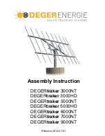
Assembly Instruction 


DEGER

traker

 3000NT 

DEGER

traker

 3000HD 

DEGER

traker 

5000NT 

DEGER

traker

 5000HD 

DEGER

traker

 6000NT 

DEGER

traker

 7000NT 

DEGER

traker

 9000NT 


Effective 2012-07-01 

Содержание DEGERtraker 3000HD

Страница 1: ...Assembly Instruction DEGERtraker 3000NT DEGERtraker 3000HD DEGERtraker 5000NT DEGERtraker 5000HD DEGERtraker 6000NT DEGERtraker 7000NT DEGERtraker 9000NT Effective 2012 07 01 ...

Страница 2: ... 6000NT Page IV 3 DEGERtraker 7000NT Page IV 4 DEGERtraker 9000NT Page IV 5 Assembly of aluminium profiles and the modules Page IV 6 Assembly of the modules Page IV 7 Assembly inverter holding optional Page IV 8 Part V Control unit Assembly control unit Page V 1 Data sheet energy converter 6 Page V 2 Data sheet Central Control Box II Page V 3 Data sheet Central Control Box III Page V 4 Connecting ...

Страница 3: ... A technology to rely on The fact that the patent protected control system and the utility model protected mechanical system were awarded the inventor s prize of the federal state of Baden Württemberg in South Germany in 2000 shows that the DEGERtraker meets the demands of both experts and investors Since this award the control unit and the mechanical system have been improved continuously The des...

Страница 4: ...upply When all electrical components fail the systems can be moved into the horizontal position by using standard tools see III 6 The development of the DEGERtrakers is based on the DIN 1055 4 Reducing the module surface the system will be able to resist higher demands than the values given in the norm The maximum mountable module surface depends on regional conditions and regulations To calculate...

Страница 5: ...________________________________________ 2nd step Assembly of integrated motor east west ______________________________________________________________________________________ 3rd step Assembly of base frame ______________________________________________________________________________________ 4th step Assembly of Elevation motor ____________________________________________________________________...

Страница 6: ...ar module A Nr Name of item p Pos A Nr Name of item p Mast 1 1 Mast 1 8100083 Rotating head 6000NT 1 2 8100006 Rotating head 7000NT 1 8100081 Base frame 6000NT 1 3 8100004 Base frame 7000NT 1 4100055 Elevation motor EMO V HD 1 4 4100038 Elevation motor EMO V 1 8100019 Boltpack rotating head 1 5 8100019 Boltpack rotating head 1 6800003 Tread locking fluid 5g 1 6 6800003 Tread locking fluid 5g 1 810...

Страница 7: ...ame CentralControlBox for 9000NT additional Wind guard 2x Thread rod BASIC STANDARD ADVANCED Pendulum for Wind guard Pos 4 Elevation motor EMO Pos 4a Bolt pack EMO Pos 5 Bolt pack rotating head Pos 7 Boomerang II Pos 9 Energy converter 6 Pos 10 Aluminum profiles Pos 11 Clamp MTH M10 Pos 12 Sliding nut M10 Pos 13 Bolt Pos 14 Bolt M10x35 M10x140 Pos 15 End Clamp Pos 16 Sliding nut M8 Pos 17 Bolt M8 ...

Страница 8: ...any uncertainty In regions and with soils at risk of frost further measures must be taken to ensure frost protection e g frost proof sub base or lean mixed concrete fill down to the frost line A formwork and reinforcement diagram for the particular foundation as shown below can be obtained for each DEGERtraker on request you must observe the instructions given in the diagrams This diagram will be ...

Страница 9: ...ng C20 30 concrete 4th Step Affix mast with 2 reinforcement against rotation Insert mast into the foundation receiving part You do not have to take account of the location of the bores in the flange ATTENTION Conduit must be inside the mast until min 10 cm above foundation top edge Align mast vertically Fill up receiving part and mast base up to the top edge of the foundation using grout concrete ...

Страница 10: ...000NT 2012 07 01 Page II 3 Example for mounting on concrete wall C20 25 Dimensions Free standing tracker Tracker building integrated ATTENTION It is necessary to dimension the mounting for every system separately according to the conditions on site The calculations are to be assigned to a local structural engineer who is responsible for the present building ...

Страница 11: ...0 7 3 0 7 tube 323 9 x 17 5 989 Ø340x85 300x300x85 modul total length free length length of mast cross section mast foundation foundation area of the mastof the mast restraint Ø w all thickness w eight dimensions dimensions m m m m mm kg cm cm 53 4 0 3 3 0 7 tube 323 9 x 7 1 205 Ø255x85 225x225x85 53 4 5 3 8 0 7 tube 323 9 x 7 1 233 Ø260x85 230x230x85 53 5 0 4 3 0 7 tube 323 9 x 8 0 292 Ø265x85 23...

Страница 12: ... the flange by using bolts M16x75 and washers M16 torque 200Nm 3rd step Mounting boomerang at the mast flange The tip of the boomerang must point in a southward direction 3 Use a GPS device or refer to the surveyor s plan of the property to determine the south position A compass is not precise enough As the boomerang is operating the end limit switch and with this the final position of the east we...

Страница 13: ...6000NT 7000NT 9000NT 2012 07 01 Page III 2 Push the boomerang as shown at the mast flange and fix it with the screws M5x18 torque 6 5Nm 4th Step Attach the limit switch setting azimuth in the free bore on the rotating head Make sure that the switch flag terminals make contact upon operation of the boomerang and that the rotation movement is stopped ...

Страница 14: ...sembling the DEGERtrakers 9000NT base frame onto the rotating head To do this push the tension rods through the longitudinal holes of the upper and lower cross member and secure each with an Washer M12 an M12 nut and an M12 self locking nut torque 15Nm Detailed view from above sectional view Lock nut M12 Nut M12 Washer M12 Tension rod with M12 thread on both sides top bottom Detailed view from bel...

Страница 15: ... always be from the centre of the cross brace to the outside 1st step Suspend the base frame by using a crane in such a way that the bore holes at the tip of rotation of the base frame are at the top and the connection for the Elevation motor EMO is on the left 5000NT 5000HD 6000NT 7000NT 9000NT 3000NT 3000HD Weight of base frame DEGERtraker 3000NT 217 kg DEGERtraker 3000HD 328 kg DEGERtraker 5000...

Страница 16: ...s with the nut too tightly to ensure that the shackles at the rotating head are not pressed together Detail ATTENTION Slide bearing bushings are installed at the rotation point of the base frame these must be slightly lubricated in the initial installation Later on lubrication is possible at any time through a lubricating nipple in the bolt M24x180 A list of suitable lubricants you find on page VI...

Страница 17: ...nd step Fix Elevation motor EMO at the base frame by using Fix Elevation motor EMO HD at the base frame by bolt M14x80 and self locking nut M14 The bolt should using bolt M20x80 and self locking nut M20 The bolt not turn during operation should not turn during operation special screw EMO special screw EMO ATTENTION Do not use any other screws except those included in the delivery Apply max one dro...

Страница 18: ...MPORTANT OPERATING INSTRUCTIONS The expansion bellows may not be pinched blocked or compressed since this can lead to damage to the internal parts A mechanical blockage of the movement of the piston rods is to be avoided since this can lead to damage to the drive system The linear actuator must come to a complete stop before changing the movement direction A fast reversal of the travel direction o...

Страница 19: ...ith the aid of the DEGERenergie dimensioning tool and may in no case be greater than 25m 1st step Arrangement of aluminium profiles Following points have to be attended in both axis modules have to be arranged symmetrically to the center of gravity 2 aluminium profiles for each row of modules attend the connecting socket on the backside of the modules Overhang of the aluminium profile y length of ...

Страница 20: ... than 40m 1st step Arrangement of aluminium profiles Distance between 2 aluminium profiles x width of module 2 attend the point of fastening from the modul manufacturer Overhang of the aluminium profile y length of aluminium profile 2 60m 2 Following points have to be attended assemble aluminium profile from the middle to the outsite in both axis modules have to be arranged symmetrically to the ce...

Страница 21: ...luminium profiles Distance between 2 aluminium profiles x width of module 2 attend the point of fastening from the modul manufacturer Overhang of the aluminium profile y length of aluminium profile 2 60m 2 Following points have to be attended assemble aluminium profile from the middle to the outsite in both axis modules have to be arranged symmetrically to the center of gravity 2 aluminium profile...

Страница 22: ...luminium profiles Distance between 2 aluminium profiles x width of module 2 attend the point of fastening from the modul manufacturer Overhang of the aluminium profile y length of aluminium profile 2 60m 2 Following points have to be attended assemble aluminium profile from the middle to the outsite in both axis modules have to be arranged symmetrically to the center of gravity 2 aluminium profile...

Страница 23: ...the point of fastening from the modul manufacturer Overhang of the aluminium profile y length of aluminium profile 2 60m 2 Following points have to be attended assemble aluminium profile from the middle to the outsite in both axis modules have to be arranged symmetrically to the center of gravity Recommendation Move the modulesurface 3 cm towards the top to reduce the self consumption of the syste...

Страница 24: ...rgie dimensioning tool and may in no case exceed the maximum allowable total module surface Maximum total module surface DEGERtraker 3000NT 3000HD 25m DEGERtraker 5000NT 5000HD 40m DEGERtraker 6000NT 53m DEGERtraker 7000NT 60m DEGERtraker 9000NT 70m Defects resulting from a too large module surface are not covered by the warranty As soon as the solar modules are installed you have to install a fun...

Страница 25: ...ce between the modules must not be more than the thickness of the bolt torque 8NM sectional view At the end of the module surface Mount the modules onto the aluminum profiles using end clamp bolt M8 and sliding nut M8 torque 20NM AFFIX WARNING NOTICE The delivered warning notice has to be affixed to the mast of every system well observable ATTENTION We strongly recommend that a gap of approximatel...

Страница 26: ...ing plate 3000NT 3000HD 5000NT 7000NT Hang up the inverter holding plate directly at the traverse of the rotating head Save the plate against lift off by using bolts M8x30 and nut M8 5000HD 6000NT 9000NT Hang up the inverter holding plate directly at the traverse of the rotating head Save the plate against lift off by using the framing square bolts M8x20 and nut M8 and washer bolt M8x30 and nut M8...

Страница 27: ...face towards the brightest spot in the sky If you are not sure you can cover a sensor cell at the DEGERconecter with your hand now the module surface should rotate in the direction of the non covered sensor cell Otherwise change connection 3 4 3rd step Controlling the elevation axis Mount the DEGERconecter with the inscription elevation LATERALLY at the solar module surface left side seen from the...

Страница 28: ...A Terminal 1 Wire blue or 2 depending on motor Terminal 2 Wire brown or 1 depending on motor 11 12 Output for DEGERconecter EL 23 V DC 0 25 A Terminal 11 Wire green Terminal 12 Wire yellow 3 4 Output for AZ motor 24 V DC 2 5 A Terminal 3 Wire blue Terminal 4 Wire brown 13 14 Output for DEGERconecter AZ 23 V DC 0 25 A Terminal 13 Wire green Terminal 14 Wire yellow 20 21 Input for safety position 21...

Страница 29: ... 7 mm monitor Grid connection Energy converter connection not included in delivery Terminal Function Terminal Function 20 Input for control input flat for special sensors 21 V DC A B Uin Input for power supply 80 380 V DC 100 265 V AC 1 A 21 Input for control input upright for special sensors 21 V DC 1 2 Remote control for EL axis 21 V DC 1 4 A Auxiliary supply output for special sensors 21 V DC 1...

Страница 30: ...ight for special sensors 21 V DC 1 2 Remote control for EL axis 21 V DC 1 4 A 22 Control input for wind monitor ADVANCED wind monitor STANDARD 3 4 Remote control for AZ axis 21 V DC 1 4 A 23 Terminal for wind monitor ADVANCED wind monitor STANDARD Auxiliary supply output for special sensors 21 V DC 1 4 A Auxiliary supply output for special sensors 21 V DC 1 4 A The clamping area on the cable fitti...

Страница 31: ...ection of the control cable has to be appropriate for the number of energy converters connected to the Central Control Box and the cable length The cable for connecting to EK 6 to CCB is not included To connect the remote control a 4 wire cable is enough to connect the optional SAFE POS a 6 wire cable is required The power supply 100 240 V for the energy converter PE L N and Central Control Box A ...

Страница 32: ... 7000NT 9000NT 2012 07 01 Page V 6 The complete control system in overview 3x0 5mm 7x0 5mm 3x1mm 4x0 5mm 7x0 5mm 3x1mm Anemometer DEGERconecter Azimuth Motor Elevation axis DEGERconecter Elevation Motor Azimuth axis Snow Sensor Energy Converter next Energy Converter next Energy Converter Evaluation unit Central Control Box Power distribution 100 240 V AC ...

Страница 33: ...to install the CCB within a building at an inaccessible place for unauthorized people A detailed assembly instruction is appended to the CCB The wind guard should be assembled at a point exposed to the wind near the DEGERtraker above the upper edge of the module An installation on the DEGERtraker is possible with the optional Pendulum for wind guard A detailed assembly instruction is appended to t...

Страница 34: ...s the brightest spot in the sky and adjusts the module surface s position to face it The DEGERtraker s mechanical system allows the accurate adjustment of the module surface to the sun all year round This technology also works in cloudy rainy or foggy conditions If for example a day starts off sunny with clouds moving in from the west in the afternoon the module surface will then move back slightl...

Страница 35: ...or changed in any kind and or accessories not from DEGERenergy are used and in case of inappropriate assembling or installation or not intended use improper use without our express permission marking of the systems DEGERtraker 3000NT 3000HD 5000NT 5000HD 6000NT 7000NT 9000NT EC directives EC machine directive 2006 42 EC EC Low Voltage Directive 73 23 EEC EC EMV directive 89 336 EWG i d F 93 31 EWG...

Страница 36: ... under an obligation to repair the damaged part or replace it with a spare part unless DEGERenergie GmbH is entitled to refuse the supplementary performance on account of statutory regulations Any replacement of individual parts within the defect period does not give rise to an extension to the validity period neither for the liability for defects in the system nor for the replaced spare part The ...

Страница 37: ...m Inplementing A A conecter East West axle is mounted pointed upwards above the solar module surface conecter elevation axle is mounted laterally at the solar module surface Measured data current consumption motor elevation current consumption motor east west locking fluid EL motor is applied Control of the assembly reinforcement of the foundation was build in due to the plan hole sphere of action...

Страница 38: ... separator or breaker It is important to ensure the technical security and the absence of voltage has been verified When voltage supply is imperative for checking the system injuries of persons have to be prevented by appropriate actions The application of the troubleshooting plan presented above enables a target oriented troubleshooting To exchange defective parts please contact us with the fault...

Страница 39: ...O For this you can find some lubricate nipples at the IMO and at the bolt M24 Fixation base frame You find recommended lubricants in the list below Addapted Lubricants for DEGERtraker Supplier Product name Art Nr Applicable temperature range DEGERenergie Grease in cartridge KG 2 3 B 6800022 40 C until 140 C ATTENTION The systems are filled up ex works with a specially grease which is not mixable w...

Страница 40: ...systems it is necessary to have this fault report on hand Without a completely filled out fault report there can not be any support provided Please send this report to the following fax number 49 7451 5391410 or scan and email to service degerenergie com Please provide a phone number to contact you RECALL NUMBER ________________________ required Fault report from ___ ___ ______ ...

Отзывы: