


Q U I C K R E F E R E N C E G U I D E
Digital Input Control
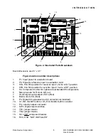
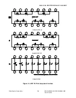
(SW1) (Refer to Figure 2, location 12)
The 10 position Switch SW1 is used to control the digital inputs of the
resolver to digital converter. When left floating (SW1 off position)
,
these
inputs are pulled up to +5V internally and can be set to a “logic 0” by setting
the appropriate SW1 switch to the “On” position.
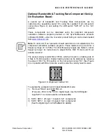
Tp6 (SW1-9) (refer to Figure 2, location 12) is an internal digital input control
used for factory testing. This input disables the digital output bits and must be
kept in the “Off” (Floating) position.
(TB2) (Refer to Figure 2, location 14)
Digital inputs DO, D1, &
Up
/ Dn are set to –5vdc using a combination of TB2
jumper settings to disable the appropriate SW1 and apply –5vdc to the
specific digital input. (See table 4 for details.)
Example: SW1 control of D0, D1 &
Up
/ Dn requires the following
configuration, TB2-J3, J5, J7 must be installed and TB2-J4, J6, J8 removed.
Table 4. Digital Input Control
RD19230 Digital Input
Logic 1 (+5vdc)
Logic 0 (Ground) -5vdc
D1 *SW1-S5
off
*TB2-J5 in, J6 out
SW1-S5 on
TB2-J5 in, J6 out
SW1-S5 don’t care
TB2-J5 out, J6 in
D0 *SW1-S6
off
*TB2-J7 in, J8 out
SW1-S6 on
TB2-J7 in, J8 out
SW1-S6 don’t care
TB2-J7 out, J8 in
up
/ Dn
*SW1-S7 off
*TB2-J3 in, J4 out
SW1-S7 on
TB2-J3 in, J4 out
SW1-S7 don’t care
TB2-J3 out, J4 in
*Factory Pre-Settings
Data Device Corporation
RD-19230EX-300 / RD-19240EX-300
User’s
Guide
11
Содержание RD-19230EX-300
Страница 8: ......


