5: Mixer Board
PRC1099A-MS
5-5
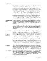
The 1650 kHz output receive signal is coupled through transformer T3 to the
1650 KHZ terminal. From the 1650 kHz IF board, the 1650 kHz receive
signal is routed to the 1650 kHz IF board.
Transmit/Receive
Switch
Transistor Q9 acts as a T/R switch, grounding the T3 secondary in receive
mode. In receive mode, Q9 is biased on from R8 (+8V); in transmit mode, R8
is 0V so Q9 is biased off, leaving the T3 secondary open. In receive mode, T3
connects the output of Q8 to the 1560 KHZ terminal.
5.1.3
ALC Circuit
The automatic level control (ALC) circuit controls the transmit power output
signal to maintain a stable radio output power. Potentiometer R37 sets the
double-balanced mixer U2 gain. It is adjusted to provide an output signal from
the Mixer board that produces a minimum transmit signal of 20W from the RF
power amplifiers on the PA board in lowest output channels—typically the
higher frequency channels (around 30 MHz).
The ALC circuit monitors the RF output power on the Audio/Filter board to
maintain the 20W output in channels where the transmit signal may exceed
20W—typically the lower frequency channels (around 2 MHz). If the output
exceeds 20W by a preset value, the ALC circuit reduces the transmit signal
level output at dual-gate FET Q11 on the Mixer board.
The ALC circuit begins on the Audio/Filter board by sampling the transmit
output power and then rectifying and amplifying the sampled current before
sending it to the Mixer board.
On the Mixer board, the ALC signal is amplified by bipolar transistor Q12 and
injected into the transmit amplifier N-channel dual-gate MOSFET Q11. If the
transmit output power signal (current) exceeds a preset level set by
Figure 5-2 ALC Frequency vs PA Output Power
40
20
Frequency (MHz)
30
20
10
5
2
U2 Gain
R37
ALC
R83
20W PA Amplifier Output
Содержание PRC1099A
Страница 4: ......
Страница 8: ......
Страница 35: ......
Страница 49: ...3 Audio Filter Board 3 14 PRC1099A MS Figure 3 2 Audio Filter Board Component Locations 738221 Rev J ...
Страница 65: ......
Страница 71: ...4 1650 kHz IF Board 4 6 PRC1099A MS Figure 4 2 1650 kHz IF Board Component Locations 738028 Rev D ...
Страница 76: ......
Страница 86: ...5 Mixer Board 5 10 PRC1099A MS Figure 5 4 Mixer Board Component Locations 738217 Rev H ...
Страница 97: ......
Страница 103: ...6 Power Amplifier Board 6 6 PRC1099A MS Figure 6 2 Power Amplifier Board Component Locations 738617 Rev C ...
Страница 117: ...7 Antenna Tuner Board PRC1099A MS 7 9 Figure 7 2 Antenna Tuner Driver Board Component Locations 738346 Rev B ...
Страница 118: ...7 Antenna Tuner Board 7 10 PRC1099A MS Figure 7 3 Antenna Tuner Board Component Locations 738027 Rev D ...
Страница 125: ......
Страница 131: ...8 Synthesizer Board 8 6 PRC1099A MS Figure 8 2 Synthesizer Board Component Locations 738025 Rev A ...
Страница 163: ...9 Processor Board 9 14 PRC1099A MS Figure 9 2 Processor Board Component Locations 738218 Rev B ...
Страница 178: ...10 Display Board 10 8 PRC1099A MS Figure 10 1 Display Board Component Location Diagram 738220 Rev G ...
Страница 181: ......
Страница 185: ...11 Junction Board 11 4 PRC1099A MS Figure 11 1 Junction Board Component Locations 738222 Rev F ...
Страница 200: ......
Страница 207: ...13 Internal Options PRC1099A MS 13 7 Figure 13 3 ALE Board Component Locations 1 of 2 738215 Rev B ...
Страница 208: ...13 Internal Options 13 8 PRC1099A MS Figure 13 4 ALE Board Component Locations 2 of 2 738215 Rev B ...
Страница 241: ......
Страница 247: ...Index 6 T Technical specifications 1 2 Transmit path 2 4 U USB 1 4 see also Modulation modes USB LSB mode V VSWR 1 4 ...


