


10: Display Board
PRC1099A-MS
10-5
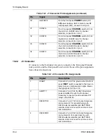
10.2.3
J3 Connector
J3 connects to the front panel Accessory connector, Audio connector, Channel
tune switch. None of the pin assignments have onboard connections.
5
EXTAMP
Connects J1 pin 30 to ground through the
front panel
POWER
switch (S7)
LO
power
position. Sets to radio to low RF output power
(5W) for use with external amplifier RA100.
6
LOPWR
Connects J1 pin 30 to ground through the
front panel
POWER
switch (S7)
LO
power
position. Sets to radio to low RF output power
(5W).
7
CHSWA
Connects J1 pin 31 to front panel
CHANNEL
switch (S1) for the A-bit in 4-bit
BCD code for channel selection.
8
CHSWB
Connects J1 pin 32 to front panel
CHANNEL
switch (S1) for the B-bit in 4-bit
BCD code for channel selection.
9
CHSWC
Connects J1 pin 33 to front panel
CHANNEL
switch (S1) for the C-bit in 4-bit
BCD code for channel selection.
10
CHSWD
Connects J1 pin 34 to front panel
CHANNEL
switch (S1) for the D -bit in 4-bit
BCD code for channel selection.
Table 10-2 J2 Connector Pin Assignments (continued)
Pin
Signal
Description
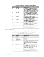
Table 10-3 J3 Connect Pin Assignments
Pin
Signal
Description
1
GND
Ground.
2
BC IN
Not used.
3
OPTION PIN
Not used.
4
EXTSEL
Connects J1 pin 18 to the RA100 external RF
amplifier through front panel Accessory
connector pin M to select the appropriate
filter.
5
DIGDN
Connects J1 pin 19 to ground when the front
panel
DIGIT
switch is pushed to the down to
select menus or alphanumeric digits. Moves
the highlight left on the LCD.
6
TUNEINIT
Connects to J1 pin 20 to a RAT7000B
antenna tuner through front panel Accessory
connector pin D to initiate a tune cycle.
Содержание PRC1099A
Страница 4: ......
Страница 8: ......
Страница 35: ......
Страница 49: ...3 Audio Filter Board 3 14 PRC1099A MS Figure 3 2 Audio Filter Board Component Locations 738221 Rev J ...
Страница 65: ......
Страница 71: ...4 1650 kHz IF Board 4 6 PRC1099A MS Figure 4 2 1650 kHz IF Board Component Locations 738028 Rev D ...
Страница 76: ......
Страница 86: ...5 Mixer Board 5 10 PRC1099A MS Figure 5 4 Mixer Board Component Locations 738217 Rev H ...
Страница 97: ......
Страница 103: ...6 Power Amplifier Board 6 6 PRC1099A MS Figure 6 2 Power Amplifier Board Component Locations 738617 Rev C ...
Страница 117: ...7 Antenna Tuner Board PRC1099A MS 7 9 Figure 7 2 Antenna Tuner Driver Board Component Locations 738346 Rev B ...
Страница 118: ...7 Antenna Tuner Board 7 10 PRC1099A MS Figure 7 3 Antenna Tuner Board Component Locations 738027 Rev D ...
Страница 125: ......
Страница 131: ...8 Synthesizer Board 8 6 PRC1099A MS Figure 8 2 Synthesizer Board Component Locations 738025 Rev A ...
Страница 163: ...9 Processor Board 9 14 PRC1099A MS Figure 9 2 Processor Board Component Locations 738218 Rev B ...
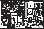
Страница 178: ...10 Display Board 10 8 PRC1099A MS Figure 10 1 Display Board Component Location Diagram 738220 Rev G ...
Страница 181: ......
Страница 185: ...11 Junction Board 11 4 PRC1099A MS Figure 11 1 Junction Board Component Locations 738222 Rev F ...
Страница 200: ......
Страница 207: ...13 Internal Options PRC1099A MS 13 7 Figure 13 3 ALE Board Component Locations 1 of 2 738215 Rev B ...
Страница 208: ...13 Internal Options 13 8 PRC1099A MS Figure 13 4 ALE Board Component Locations 2 of 2 738215 Rev B ...
Страница 241: ......
Страница 247: ...Index 6 T Technical specifications 1 2 Transmit path 2 4 U USB 1 4 see also Modulation modes USB LSB mode V VSWR 1 4 ...