9: Processor Board
9-8
PRC1099A-MS
9.1.20
Specifications
Note:
These specifications are subject to change without notice or
obligation.
LSB Receiver
Tests the receiver circuitry in lower sideband mode. An audible
tone is heard for at least two seconds in the handset. If BITE
does not detect the tone,
LSB FAIL
displays and BITE stops.
Otherwise,
LSB PASS
is displayed and BITE proceeds to next
step.
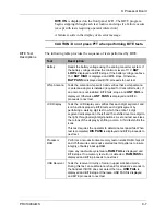
Transmitter
Exercises the transmitter functions. It begins by tuning the
Synthesizer to one of six test frequencies in USB mode (see
table below). It sets the radio to low power and attempts to tune
the antenna to the current test frequency. An audible test tone is
generated through the handset for two seconds and verified by
the operator. If radio passes, BITE switches the transmitter to
high power for two seconds (if the resulting antenna tune setting
includes L8, L9, or L10, transmitter stays in low power).
Operator verifies the test tone is audible. If the antenna tuning
fails to tune during transmitter test sequence, BITE displays
XXX
FAIL
(XXX = current test frequency). If the test tone is not
present or fades during the low/high power sections of any
transmitter tests, the current test is failed by the operator.
Test
Description
29.9 Test
29.9000 MHz
19.9 Test
19.9000 MHz
12.9 Test
12.9000 MHz
7.9 Test
7.9000 MHz
4.9 Test
4.9000 MHz
2.9 Test
2.9000 MHz
Table 9-1 Processor Board Specifications
Characteristic
Specification
Current Drain
Static: 20 mA typical at 5V
Operating: 40 mA typical at 5V
Lithium Cell:
A typical at 2.5V
Lithium Cell Life
5 years minimum, 10 years typical
Содержание PRC1099A
Страница 4: ......
Страница 8: ......
Страница 35: ......
Страница 49: ...3 Audio Filter Board 3 14 PRC1099A MS Figure 3 2 Audio Filter Board Component Locations 738221 Rev J ...
Страница 65: ......
Страница 71: ...4 1650 kHz IF Board 4 6 PRC1099A MS Figure 4 2 1650 kHz IF Board Component Locations 738028 Rev D ...
Страница 76: ......
Страница 86: ...5 Mixer Board 5 10 PRC1099A MS Figure 5 4 Mixer Board Component Locations 738217 Rev H ...
Страница 97: ......
Страница 103: ...6 Power Amplifier Board 6 6 PRC1099A MS Figure 6 2 Power Amplifier Board Component Locations 738617 Rev C ...
Страница 117: ...7 Antenna Tuner Board PRC1099A MS 7 9 Figure 7 2 Antenna Tuner Driver Board Component Locations 738346 Rev B ...
Страница 118: ...7 Antenna Tuner Board 7 10 PRC1099A MS Figure 7 3 Antenna Tuner Board Component Locations 738027 Rev D ...
Страница 125: ......
Страница 131: ...8 Synthesizer Board 8 6 PRC1099A MS Figure 8 2 Synthesizer Board Component Locations 738025 Rev A ...
Страница 163: ...9 Processor Board 9 14 PRC1099A MS Figure 9 2 Processor Board Component Locations 738218 Rev B ...
Страница 178: ...10 Display Board 10 8 PRC1099A MS Figure 10 1 Display Board Component Location Diagram 738220 Rev G ...
Страница 181: ......
Страница 185: ...11 Junction Board 11 4 PRC1099A MS Figure 11 1 Junction Board Component Locations 738222 Rev F ...
Страница 200: ......
Страница 207: ...13 Internal Options PRC1099A MS 13 7 Figure 13 3 ALE Board Component Locations 1 of 2 738215 Rev B ...
Страница 208: ...13 Internal Options 13 8 PRC1099A MS Figure 13 4 ALE Board Component Locations 2 of 2 738215 Rev B ...
Страница 241: ......
Страница 247: ...Index 6 T Technical specifications 1 2 Transmit path 2 4 U USB 1 4 see also Modulation modes USB LSB mode V VSWR 1 4 ...


