Aespire View
5-10
M1132382
WARNING
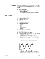
Agent mixtures from the low-pressure leak test stay in the
system. Clear the system by flowing O2 at 1 l/min for one
minute.
8. Clear the system of agent.
•
Set the System switch to On.
•
Set the O2 flow to 1 l/min.
•
Flow O2 for one minute.
•
Turn the O2 flow control fully clockwise for minimum flow.
Positive low-
pressure leak test
1. Connect the test device to the ACGO port with the positive-
pressure leak test adapter.
Note
Push the positive-pressure leak test adapter into the ACGO port
throughout the test to maintain a tight seal.
CAUTION
Do a positive low-pressure leak test at the ACGO port
only.
2. Turn the ACGO switch to the ACGO position.
3. Turn all flow controls fully clockwise for minimum flow.
4. Turn all vaporizers off.
5. Fully open the needle valve on the test device.
Note
Keep the test device flow tube vertical for accurate results.
CAUTION
If the needle valve is not fully open, this test can damage
the pressure gauge on the test device.
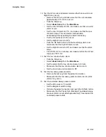
6. Open the O2 flow control and set for a total flow on the test
device of 0.4 l/min.
7. Make sure that the pressure gauge on the test device is at zero,
and make sure that all other flow controls are fully closed.
8. Close the needle valve on the test device until the gauge reads
20 kPa (3 psi) for (BSI) or 3 kPa (.4 psi) for ISO.
9. If the flow through the test device is less than 0.35 l/min ISO or
0.3 l/min (BSI), there is a low pressure leak in the system. See
in the
section.
10. Test each vaporizer.
•
Turn on the vaporizer being tested, and set it to 1%.
•
Perform steps 5 through 9 of this test for each vaporizer.
11. Make sure all vaporizers are turned off.
Содержание Aespire View
Страница 1: ...Aespire View User s Reference Manual Software Revision 6 X...
Страница 16: ...Aespire View 1 8 M1132382...
Страница 46: ...Aespire View 3 16 M1132382...
Страница 50: ...Aespire View 4 4 M1132382...
Страница 88: ...Aespire View 7 8 M1132382...
Страница 112: ...Aespire View 9 10 M1132382...
Страница 114: ...Aespire View 10 2 M1132382 System pneumatic circuits Figure 10 1 Pneumatic circuit diagram AC 20 001...
Страница 118: ...Aespire View 10 6 M1132382 Electrical block diagram Figure 10 2 Electrical block diagram AC 20 008...
Страница 137: ...10 Specifications and Theory of Operation M1132382 10 25 Figure 10 9 Gas composition related errors AB 74 027...
Страница 148: ...Aespire View I 4 M1132382...


