background image

Aespire View

3-8

M1132382

Cardiac Bypass

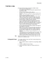
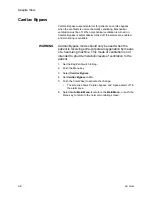
Cardiac Bypass suspends alarms for patients on cardiac bypass 
when the ventilator is not mechanically ventilating. Mechanical 
ventilation must be off. When mechanical ventilation is turned on, 
Cardiac Bypass is automatically turned off, the alarms are enabled, 
and monitoring is available.

WARNING

Cardiac Bypass mode should only be used when the 

patient is receiving extra-corporeal oxygenation by means 

of a heart-lung machine. This mode of ventilation is not 

intended to provide metabolic levels of ventilation to the 

patient.

1. Set the Bag/Vent switch to Bag.

2. Push the Menu key.

3. Select 

Cardiac Bypass

.

4. Set 

Cardiac Bypass

 to 

On

.

5. Push the ComWheel to activate the change.

The screens shows ‘Cardiac bypass’ and ‘Apnea alarm off’ in 
the alarm area.

6. Select 

Go to Main Menu

 to return to the 

Main Menu

, or push the 

Menu key to return to the normal monitoring screen.

Содержание Aespire View

Страница 1: ...Aespire View User s Reference Manual Software Revision 6 X...

Страница 2: ...er of this Product shall have the sole responsibility for any malfunction which results from improper use faulty maintenance improper repair damage or alteration by anyone other than Datex Ohmeda CAUT...

Страница 3: ...er controls 2 8 ACGO 2 10 Scavenging the ACGO sample flow 2 11 Scavenging from an auxiliary manual breathing circuit 2 11 Scavenging a gas monitor sample flow 2 11 Ventilator controls 2 12 Ventilator...

Страница 4: ...onal 3 15 4 Preoperative Checkout Every day before your first patient 4 2 Before every patient 4 3 5 Preoperative Tests Inspect the system 5 2 Power failure alarm test 5 3 Pipeline test 5 3 Total flow...

Страница 5: ...tests 6 10 Breathing system problems 6 12 Electrical problems 6 13 Pneumatic problems 6 14 7 User Maintenance Repair policy 7 2 Maintenance summary and schedule 7 2 User maintenance 7 3 Datex Ohmeda a...

Страница 6: ...ts 8 10 Scavenging 8 11 Sample gas return port 8 11 Suction regulator optional 8 12 Auxiliary O2 flowmeter optional 8 12 How to install gas cylinders 8 13 Pin indexed cylinder yokes 8 13 DIN cylinder...

Страница 7: ...ower 10 7 Power cord 10 8 Battery information 10 8 Flow specifications 10 9 Pneumatic flow 10 9 Breathing system specifications 10 10 Gas scavenging 10 11 Physical specifications 10 12 Environmental r...

Страница 8: ...laration electromagnetic emissions 10 26 Guidance and manufacturer s declaration electromagnetic immunity 10 27 Recommended separation distances 10 29 Electrical safety 10 30 IEC 60601 1 Classificatio...

Страница 9: ...M1132382 1 1 1 Introduction In this section Intended use 1 2 Symbols used in the manual or on the equipment 1 3 Typeface conventions used 1 6 Abbreviations 1 6...

Страница 10: ...ures A serial interface permits communication to external monitoring This anesthesia system is not suitable for use in an MRI environment This system must only be operated by medical personnel authori...

Страница 11: ...tor or the patient Cautions tell about a condition that can cause damage to the equipment Read and follow all warnings and cautions On power Off power Standby O2 O2 flush button Type BF equipment Type...

Страница 12: ...sitive polarity Minus negative polarity Bag position manual ventilation Mechanical ventilation Inspiratory flow Expiratory flow Movement in one direction Movement in two directions Lock Unlock Isolati...

Страница 13: ...number of the Notified Body used by GE Healthcare s Quality Systems Authorized representative in the European Community Manufacturer Date of manufacture Indicates that the waste of electrical and elec...

Страница 14: ...lic typeface and enclosed in double quotes for example System Controls and Menus Abbreviations Abbreviation Definition A ABS Advanced breathing system ACGO Auxiliary common gas outlet AGSS Anesthetic...

Страница 15: ...pressure measured at the end of Tpause Ppeak Maximum airway pressure measured during patient breath Psupport Pressure support PSVPro Pressure supported ventilation with apnea backup R RR Respiratory...

Страница 16: ...Aespire View 1 8 M1132382...

Страница 17: ...ot use antistatic or electrically conductive breathing tubes or masks They can cause burns if used near high frequency surgical equipment In this section Anesthesia system controls 2 2 Advanced breath...

Страница 18: ...vetail rails 9 O2 flush button 3 Vaporizer 10 Auxiliary O2 flow control optional 4 Pipeline pressure gauge s upper row 11 Breathing system 5 Cylinder pressure gauge s lower row 12 Flow controls 6 Syst...

Страница 19: ...ble vacuum turn the knob clockwise to increase the vacuum and counterclockwise to decrease the vacuum 8 Brake Push down to lock Lift to release 9 O2 flush button Push the O2 flush button to supply hig...

Страница 20: ...1132382 Figure 2 2 Rear view 1 Outlet circuit breaker 5 Mains inlet 2 Electrical outlet 6 System circuit breaker 3 Suction items optional 7 Cylinder 4 Equipotential stud 8 Pipeline connections 1 2 4 5...

Страница 21: ...Manual bag port 3 Auxiliary common gas outlet ACGO switch 12 Adjustable pressure limiting APL valve 4 ACGO 13 Bag Vent switch 5 Inspiratory flow sensor 14 Bellows assembly 6 Expiratory flow sensor 15...

Страница 22: ...dal volume delivery 8 Absorber canister release Push to remove the canister This causes the breathing system to vent to the room unless the EZchange canister option is installed Be sure to hold the ca...

Страница 23: ...043 AB 74 120 1 2 3 4 5 Item Figure 2 4 Description 1 Bag support arm Squeeze the button to raise or lower the arm 3 EZchange canister release Push to drop the canister to EZchange position This seals...

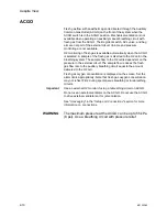
Страница 24: ...er s Reference manual for more detailed information on the vaporizer 1 Tec 6 series 2 Tec 7 3 Lock lever 4 Concentration control and release 5 Indicators Tec 6 series 6 Silence alarm touch key Tec 6 s...

Страница 25: ...The Tec 6 series concentration control does not turn as long as the warm up indicator is on 5 Indicators Tec 6 series All indictors come on briefly at the start The warm up indicator goes off after ap...

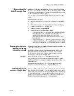
Страница 26: ...mple flow to the O2 cell is dependent on the pressure in the external circuit The sample flow reduces the fresh gas flow rate to the auxiliary breathing circuit equal to the amount delivered to the O2...

Страница 27: ...lowly with the sample flow When the bag is full the sample flow goes to the AGSS Scavenging from an auxiliary manual breathing circuit Scavenge the exhaust if an auxiliary manual breathing circuit is...

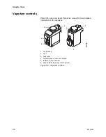
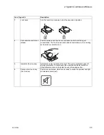
Страница 28: ...ical ventilation Figure 2 6 Ventilator controls 1 High priority alarm indicator 8 PEEP quick key 2 Low or medium priority alarm indicator 9 Pmax or Psupport quick key 3 Alarm silence key 10 I E or Tin...

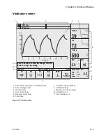
Страница 29: ...entilation status 4 Alarm limit settings 10 Ventilation mode 5 Measured values area 11 User message area 6 Circuit type AC 20 004 Total TV ml Vent On RR min I E Pmax cmH2O PEEP cmH2O More Settings VCV...

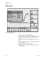
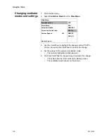
Страница 30: ...urn the ComWheel clockwise or counterclockwise to highlight the desired selection 5 Push the ComWheel to confirm the selection 6 Push the Menu key to exit the menu and return to the normal monitoring...

Страница 31: ...al ventilation 3 2 Start manual ventilation 3 2 Ventilator setup 3 3 Alarm Setup 3 5 Setup Calibration 3 6 Screen and audio setup 3 7 Cardiac Bypass 3 8 Measure circuit compliance 3 9 Pressure wavefor...

Страница 32: ...ided to show progress Start mechanical ventilation WARNING Make sure that the patient circuit is correctly assembled and that the ventilator settings are clinically appropriate before starting ventila...

Страница 33: ...ransitions to SIMV PC where it delivers a minimum number of mechanically controlled breaths Synchronized Intermittent Mandatory Ventilation with Pressure Control SIMV PC optional Sets a minimum number...

Страница 34: ...to confirm the change 4 Set the values for the selected ventilation mode The value is highlighted while being set 5 Push the ComWheel or the quick key to activate the change The system returns to the...

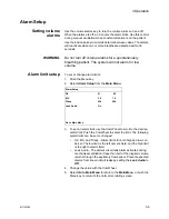
Страница 35: ...om the Main Menu 3 To set an alarm limit use the ComWheel to scroll to the desired alarm limit Push the ComWheel to select the limit The following alarm limits can be set or changed O2 MV and TVexp Al...

Страница 36: ...ow Trigger End of Breath Backup Mode Active Tpause Rise Rate Note See the Specifications and Theory of Operation section for more information on individual settings 4 After selecting a ventilator sett...

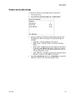
Страница 37: ...me or loudness of audible alarms Alarm Limits Simplifies the screen by hiding the alarm limits To do this select Hide for this option If the screen is set to hide the alarm limits the limits automatic...

Страница 38: ...mode should only be used when the patient is receiving extra corporeal oxygenation by means of a heart lung machine This mode of ventilation is not intended to provide metabolic levels of ventilation...

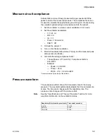
Страница 39: ...tidal volume TVexp and the measured peak airway pressure Ppeak 6 Calculate the tubing compliance factor TVexp Ppeak 2 5 cmH2O Compliance factor in ml cmH2O Example Ppeak 30 cmH2O TVexp 25 ml 25 30 2...

Страница 40: ...stems with EZchange canister have the following label on the canister holder When the system is in EZchange position the message No CO2 absorption shows on the ventilator display To return to absorber...

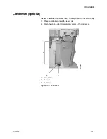
Страница 41: ...isually check the condenser reservoir daily Drain the reservoir daily 1 Place a container under the reservoir 2 Push the drain button to empty any water in the condenser 1 Drain button 2 Reservoir 3 C...

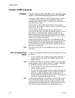
Страница 42: ...open connection essentially at atmospheric pressure such as to an exhaust grill Note See Setup and Connections for additional scavenging connection information Connecting passive AGSS To use the opti...

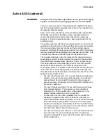
Страница 43: ...ng circuit If more than a small amount of negative pressure 0 3 cmH2O is applied to the scavenging system the negative relief valve opens allowing room air to be drawn into the scavenging system inste...

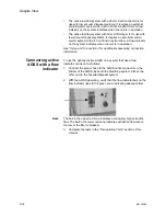
Страница 44: ...onnections for additional scavenging connection information Connecting active AGSS with a flow indicator To use the optional active AGSS on a system that has a flow indicator connect it as follows 1 C...

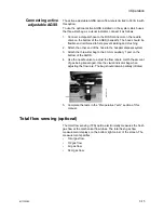
Страница 45: ...se to the hospital disposal system 3 Attach the three liter bag to the 30 mm auxiliary 1 port on the bottom of the AGSS 4 Use the needle valve to adjust the flow rate to match the amount of gas being...

Страница 46: ...Aespire View 3 16 M1132382...

Страница 47: ...system component How to test each system component w Before using this system Complete the preoperative checkout For in depth test instructions see the Preoperative Tests section Test all other syste...

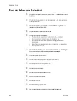
Страница 48: ...Each vaporizer is locked and cannot be removed The alarms and indicators operate correctly Tec 6 series vaporizers More than one vaporizer cannot be turned on at the same time All vaporizers are full...

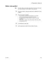
Страница 49: ...equipment is available and in good condition Check the vaporizer installation The top of each vaporizer is horizontal not on crooked Each vaporizer is locked and cannot be removed The alarms and indic...

Страница 50: ...Aespire View 4 4 M1132382...

Страница 51: ...ure alarm test 5 3 Pipeline test 5 3 Total flow sensing test if equipped 5 3 Cylinder test 5 4 Flow control test 5 5 Vaporizer installation 5 7 Vaporizer back pressure test 5 8 Low pressure leak test...

Страница 52: ...models with cylinder supplies Models with cylinder supplies have a cylinder wrench attached to the system Models with cylinder supplies have a reserve supply of O2 connected to the machine during syst...

Страница 53: ...ols to mid range Make sure that all of the gauges except for O2 go to zero Disconnect the O2 supply Make sure that the O2 gauge goes to zero As the pressure decreases the alarms for O2 supply failure...

Страница 54: ...upply Make sure that the O2 gauge goes to zero As the pressure decreases the alarms for O2 supply failure should occur 3 Make sure that the cylinders are full Open each cylinder valve Make sure that e...

Страница 55: ...lfunction of the Link 25 system It does not confirm the proper calibration of the Link 25 system Perform periodic calibrations using an accurate and properly calibrated O2 monitor as recommended in th...

Страница 56: ...table 8 Adjust the flow of all gases through the full range and make sure that the flow tube floats move smoothly 9 Disconnect the O2 pipeline supply or close the O2 cylinder valve 10 Make sure that T...

Страница 57: ...izer lock lever to the locked position 4 Try to lift each vaporizer straight up off the manifold Do not pull forward on the vaporizer Do not rotate the vaporizer on the manifold 5 If the vaporizer lif...

Страница 58: ...ure that the O2 flow stays constant and the float moves freely 4 Adjust the vaporizer concentration from 0 to 1 The O2 flow must not decrease more than 1 l min through the full range If the O2 flow de...

Страница 59: ...est device inflates in less than 60 seconds use a different test device 5 Test the system for low pressure leaks Turn the flow controls one and a half turns counterclockwise Connect the test device to...

Страница 60: ...urn all vaporizers off 5 Fully open the needle valve on the test device Note Keep the test device flow tube vertical for accurate results CAUTION If the needle valve is not fully open this test can da...

Страница 61: ...400 ml Rate 12 I E 1 2 Pmax 40 cmH2O PEEP Off 7 Set the O2 flow to the minimum flow 8 Turn off all other gases 9 Push the O2 flush button to fill the bellows 10 Set the Bag Vent switch to Bag and the...

Страница 62: ...et the High O2 alarm to Off and make sure that the alarm stops Flow 100 O2 for 2 minutes and make sure that the O2 cell measures 100 O2 13 Test the low minute volume alarm Push the Menu key Select Ala...

Страница 63: ...cts in the breathing system can stop gas flow to the patient causing injury or death Use a test plug that is the appropriate size so that it will not fall into the breathing system After performing th...

Страница 64: ...n the breathing circuit APL valve test 1 Set the System switch to On 2 Occlude the patient connection 3 Occlude the bag port 4 Set the APL valve to 70 cmH2O 5 Set the O2 flow to 3 l min Make sure that...

Страница 65: ...e bellows 9 Make sure that Mechanical ventilation starts A subatmospheric pressure alarm does not occur The ventilator shows the correct data based on settings The bellows inflate and deflate during m...

Страница 66: ...l vaporizers off Set the APL valve to MIN Set the Bag Vent switch to Bag Set all flow controls to minimum Set sufficient patient suction Make sure that the breathing system is correctly connected and...

Страница 67: ...rocedures w Do not use malfunctioning equipment Contact a Datex Ohmeda trained representative for service w No repair should ever be attempted by anyone not having experience in the repair of devices...

Страница 68: ...e level of risk to the patient A high priority alarm tone sounds in two bursts of five tones a 10 second pause and then repeats Some high priority alarms can be silenced for 120 seconds Medium priorit...

Страница 69: ...in this condition until it is acknowledged by pushing the Alarm silence key or until the alarm reoccurs When the alarm is acknowledged it is removed from the screen If an alarm has latched and the al...

Страница 70: ...r mechanical ventilation or ventilation with monitoring select the circle system setting Apnea 120 s High No mechanical breaths or spontaneous breaths greater than 5 ml in last 120 seconds Check the p...

Страница 71: ...it leak audio can be turned off in the Alarm Setup menu Circuit leak audio off Informational Leak Audio is set to Off on the Alarm Setup menu Turn Leak Audio to On on the Alarm Setup menu Connect O2 s...

Страница 72: ...ater after the ventilator settings are changed Check patient for spontaneous breathing Adjust control settings MVexp low Medium Exhaled minute volume less than the low limit alarm setting This alarm i...

Страница 73: ...ntinues with reduced accuracy Replace the flow sensor Replace insp flow sensor Informational The system cannot read the calibration data stored in the sensor Operation continues with reduced accuracy...

Страница 74: ...ossible leak Modify settings or check for system leaks Unable to drive bellows Informational Manifold pressure is greater than Paw Check the drive gas Increase fresh gas flow or push the O2 flush butt...

Страница 75: ...only appears in the Alarm message area and a specific failure message appears in the User message area The following are minimum system monitoring alarms Manifold pressure sensor failure Pressure limi...

Страница 76: ...2 Plimit 40 cmH2O PEEP Off Anesthesia machine O2 flow minimum flow 25 75 ml min All other gases Off Push O2 flush button to fill bellows 5 Set the O2 concentration to 30 and allow the O2 reading to st...

Страница 77: ...Test the MVexp low alarm Go to the Alarm Setup menu Set the MV low alarm limit to 6 0 l min Make sure the MVexp low alarm occurs Set the MV low alarm limit to Off 8 Test the Ppeak high alarm Set Pmax...

Страница 78: ...ir the system The ventilator does not read the position of the Bag Vent switch Ventilator or absorber malfunction Ventilate manually Contact a Datex Ohmeda trained service representative to repair the...

Страница 79: ...to had no power Use a different electrical socket An internal fuse is open Have a Datex Ohmeda trained service representative repair the system One electrical outlet does not have power The outlet ci...

Страница 80: ...ctly install the vaporizer The vaporizer filler is loose funnel fill type vaporizer Tighten the filler Vaporizer port o rings external are damaged or not installed Install new o rings A vaporizer malf...

Страница 81: ...hemical reactions when exposed to inhalation anesthetics Adequate precautions should be taken to ensure that absorbent does not dry out Turn off all gases when finished using the system w Obey infecti...

Страница 82: ...is nature Replace damaged parts with components manufactured or sold by Datex Ohmeda Then test the unit to ascertain that it complies with Datex Ohmeda s published specifications Contact a Datex Ohmed...

Страница 83: ...100 O2 During cleaning and setup Inspect the parts for damage Replace or repair as necessary Annually Replace the external o rings on the vaporizer ports As necessary Install new cylinder gaskets on c...

Страница 84: ...system 3 Remove the cable connector from the O2 cell and unscrew the cell counterclockwise Important Make sure that the o ring is on the replacement O2 cell before installation 4 Install the replaceme...

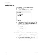
Страница 85: ...ion before performing the 100 O2 cell calibration 1 Push the Menu key 2 Select Setup Calibration 3 Select O2 Sensor Calibration 4 Select 21 O2 5 Remove the O2 cell from the circuit Pull the latch to u...

Страница 86: ...O2 cell calibration Then try a 100 O2 cell calibration again If the 100 O2 cell calibration does not pass replace the O2 cell 7 Perform the Breathing system tests in the Preoperative Tests section be...

Страница 87: ...w sensor or water in the sensing lines can cause inaccurate alarms Small beads of water or a foggy appearance in the flow sensors is acceptable To manage excess water Empty the water reservoir in the...

Страница 88: ...Aespire View 7 8 M1132382...

Страница 89: ...2 8 1 8 Setup and Connections In this section Canister setup 8 4 Electrical connections 8 9 Pneumatic connections 8 10 How to install gas cylinders 8 13 How to attach equipment to the top of the machi...

Страница 90: ...ll not Cause an allergic reaction in the patient React with the anesthetic gases or agent to produce dangerous by products w To prevent incorrect values or equipment malfunction use only cables hoses...

Страница 91: ...ctrosurgical equipment prevents safe use of the ventilator w Do not use antistatic or electrically conductive breathing tubes or masks They can cause burns if used near high frequency surgical equipme...

Страница 92: ...tup 1 Canister support pin 2 Canister handle 3 Disposable Multi Absorber canister 4 Absorbent 5 Expiratory water reservoir 6 Canister release latch 7 Reusable Multi Absorber canister Figure 8 1 Canist...

Страница 93: ...of a case During non use absorbent can go back to the original color Refer to the absorbent labeling for more information about color changes If the absorbent completely dries out it may give off carb...

Страница 94: ...to change the canister Discard the absorbent when it has changed color If left standing for several hours absorbent may regain its original color giving a misleading indication of activity Important...

Страница 95: ...nister cradle release latch to unlock the canister cradle 2 Slide the canister up and out of the cradle Reusable Multi Absorber canister filling 1 Turn the canister upside down and using your thumbs t...

Страница 96: ...r in the Cleaning and Sterilization manual 6 Assemble canister Place a new filter in the bottom of the canister Pour absorbent into the canister Place a new filter over the absorbent Align the cover s...

Страница 97: ...on the support pins or in the EZchange canister module before latching it into place Electrical connections Outlets Labels show outlet voltage ratings and circuit breaker amp ratings These are isolate...

Страница 98: ...quipment DCE configuration Pin 1 Monitor On Standby Pin 5 Signal ground Pin 6 Receive data Pin 9 Monitor On Standby Return Pin 13 Transmit data Pneumatic connections CAUTION Use only medical grade gas...

Страница 99: ...ing system Adapters may be necessary to interface to the scavenging connector See the Operation section for more scavenging information Sample gas return port Connect the sample gas exhaust tube from...

Страница 100: ...regulators must be connected to an external vacuum supply 1 External vacuum non venturi connection 2 Venturi muffler 3 Collection bottle connection 4 Splash guard 5 Overflow safety trap Auxiliary O2 f...

Страница 101: ...e the cap if equipped from the cylinder valve on the new cylinder WARNING Make sure there is only one gasket on the cylinder connection No gasket or more than one gasket can cause a leak 7 Install a n...

Страница 102: ...ir a leak install a new cylinder gasket and tighten the tee handle 8 Repeat the leak test If the leak continues do not use the system How to attach equipment to the top of the machine WARNING Do not e...

Страница 103: ...components refer to the Technical Reference manual In this section Flow sensor module 9 2 Exhalation valve assembly 9 2 Breathing circuit module 9 3 Bellows assembly 9 4 Absorber canister 9 5 AGSS 9...

Страница 104: ...ule does not include flow sensors 1407 7001 000 1 Flow sensor cover 1407 3000 000 2 Flow sensor cuff 1407 3004 000 3 Flow sensor disposable plastic non offset 1503 3858 000 Flow sensor disposable plas...

Страница 105: ...Stock number Breathing circuit module does not include O2 cell o ring or cable 1407 7002 000 1 Check valves circuit lens 1407 3101 000 2 Check valve assembly 1406 8219 000 3 O ring for O2 cell or plug...

Страница 106: ...Rim 1500 3351 000 4 Pressure relief valve assembly 1500 3377 000 5 Latch rim 1500 3352 000 6 Manifold bellows base 1407 3702 000 7 Bellows base with latch 1407 7006 000 8 Seal base 1500 3359 000 9 Di...

Страница 107: ...pack of foam does not include absorbent 1407 7004 000 2 Cover assembly CO2 canister 1009 8240 000 3 Foam CO2 canister pack of 40 1407 3201 000 4 O ring 1407 3204 000 5 Canister CO2 with handle 1407 3...

Страница 108: ...mbscrew M6 X 28 5 1406 3305 000 Thumbscrew M6 X 43 1406 3304 000 Valve unidirectional complete assembly 1406 8219 000 Passive AGSS Adapter outlet 30 mm female to 19 mm male pack of 5 1500 3376 000 Exh...

Страница 109: ...Item Description Stock number 1 EZchange canister module includes valve and cap 1407 7021 000 2 Valve 1407 3126 000 3 Cap 1407 3130 000 4 Condenser 1407 7024 000 EZchange canister module with condense...

Страница 110: ...espire View 9 8 M1132382 Condenser 1 2 AB 82 045 Item Description Stock number Condenser assembly includes module and condenser 1407 7026 000 1 Condenser module 1407 7025 000 2 Condenser 1407 7024 000...

Страница 111: ...ow pressure leak test device BSI 1001 8975 000 Positive low pressure leak test device ISO 1001 8976 000 Positive pressure leak test adapter 1009 3119 000 Ring sealing gasket for DIN 477 and O2 high pr...

Страница 112: ...Aespire View 9 10 M1132382...

Страница 113: ...5 Electrical block diagram 10 6 Electrical power 10 7 Flow specifications 10 9 Breathing system specifications 10 10 Physical specifications 10 12 Environmental requirements 10 12 Suction regulators o...

Страница 114: ...Aespire View 10 2 M1132382 System pneumatic circuits Figure 10 1 Pneumatic circuit diagram AC 20 001...

Страница 115: ...nt switch 18 Link 25 50 Bag 19 Flowmeter module single flow tubes optional 51 APL valve 20 Gas inlet valve assembly 52 Gas monitor optional external gas monitor 21 Air flow meter assembly optional 53...

Страница 116: ...ve supplies high flows of O2 to the fresh gas outlet when you push the flush button The flush switch uses pressure changes to monitor the position of the flush valve When the System switch is ON O2 fl...

Страница 117: ...tions CAUTION All gases supplied to the system must be medical grade Gas supplies ACGO Port relief Valve limits fresh gas pressure to 138 kPa 20 psi at the flush flow Pipeline gases O2 Air N2O Cylinde...

Страница 118: ...Aespire View 10 6 M1132382 Electrical block diagram Figure 10 2 Electrical block diagram AC 20 008...

Страница 119: ...optional 38 Left membrane switch 17 CPU board 39 Bottom membrane switch 18 LCD 40 Right membrane switch 19 ComWheel 41 USB I O port 20 Ventilator engine board 42 Network I O port Ethernet 21 Gas inle...

Страница 120: ...onditions The system functions to specifications through the transition to battery power CAUTION Contact a Datex Ohmeda trained service representative to replace or disconnect the battery if the equip...

Страница 121: ...te 14 7 psi flowmeter accuracy agrees with VDE 3513 Part 3 Accuracy Class 2 5 or better Different breathing circuit pressures barometric pressures or temperatures change the accuracy With some conditi...

Страница 122: ...iance bag mode only 1 82 ml 0 098 kPa 1 cmH2O 55 ml 3 kPa 30 cmH2O With EZchange canister system and condenser 2 67 ml 0 98 kPa 1 cmH2O 80 ml 3 kPa 30 cmH2O Pressure required to open Inspiratory or ex...

Страница 123: ...type Outlet connector Hospital waste gas disposal system requirements Adjustable flow high vacuum DISS EVAC 305 mmHg 12 inHg minimum at 36 l min flow High flow low vacuum BSI 30 mm threaded BS6834 50...

Страница 124: ...5 in Depth 74 cm 29 1 in Weight 136 kg 300 lb Top of machine weight limit 34 kg 75 lb Casters 12 5 cm 4 9 in with brakes on the front casters Drawers 17 5 cm x 33 cm x 26 5 cm 6 9 in x 13 in x 10 4 i...

Страница 125: ...29 l min with pipeline drive gas at 280 kPa 41 psi 32 l min with pipeline drive gas at 600 kPa 87 psi Vacuum Gauge Accuracy 5 of full scale Values are approximate Approximate values are at sea level P...

Страница 126: ...for volume related numerics and alarms The ventilator also uses the flow sensors to adjust its output for changes in fresh gas flow and small leaks in the breathing system In volume ventilation modes...

Страница 127: ...erature of the monitored gas mixture A thermistor in the cell s housing automatically compensates for temperature changes in the cell O2 monitoring uses signal processing and analyzing circuitry to co...

Страница 128: ...in the lungs A typical volume controlled pressure waveform increases throughout the entire inspiratory period and rapidly decreases at the start of expiration The ventilator adjusts gas flow to the b...

Страница 129: ...ratory pressure The flow then decreases to maintain the set pressure Pinsp Pressure sensors in the ventilator measure patient airway pressure The ventilator automatically adjusts the flow to maintain...

Страница 130: ...the patient The ventilator will always deliver the specific number of breaths per minute that the clinician has set In SIMV PSV the spontaneous breaths can be pressure supported to assist the patient...

Страница 131: ...the ventilator uses to end the inspiratory phase of the breath and to cycle into the expiratory phase If the inspiration termination is set to 30 then the ventilator will stop inspiration when the flo...

Страница 132: ...sp sets the target airway pressure RR sets the rate of mechanically driven breaths Tinsp sets the inspiration time for a mechanical breath Psupport sets the pressure support level Pmax sets the maximu...

Страница 133: ...g the expiratory phase a support for a spontaneous breath is provided with pressure support added as set by the clinician SIMV PC settings include Pinsp sets the target airway pressure RR sets the rat...

Страница 134: ...inspiratory pressure change between breaths is a maximum of 3 cmH2O This mode will deliver breaths with the efficiency of pressure controlled ventilation yet still compensate for changes in the patie...

Страница 135: ...arm range when PEEP high Blockage alarm occurs 6 to 42 cmH2O 1 cm increment mechanical ventilation 6 to 30 cmH2O 1 cm increment manual ventilation Tidal volume display range 5 to 9999 ml 1 ml resoluti...

Страница 136: ...ressure PEEP accuracy of 1 5 cmH2O Monitoring accuracy Volume control Greater than 210 ml tidal volume accuracy of 9 of TV 60 to 210 ml tidal volume accuracy of 18 ml Less than 60 ml tidal volume accu...

Страница 137: ...10 Specifications and Theory of Operation M1132382 10 25 Figure 10 9 Gas composition related errors AB 74 027...

Страница 138: ...ment in the system before use on patients Guidance and manufacturer s declaration electromagnetic emissions The system is suitable for use in the specified electromagnetic environment The customer and...

Страница 139: ...2 kV common mode Mains power quality should be that of a typical commercial and or hospital environment Voltage dips short interruptions and voltage variations on power supply input lines IEC 61000 4...

Страница 140: ...and 40 66 MHz to 40 70 MHz The compliance levels in the ISM frequency bands between 150 kHz and 80 MHz and in the frequency range 80 MHz to 2 5 GHz are intended to decrease the likelihood that a port...

Страница 141: ...er not listed above the recommended separation distance D in meters m can be determined using the equation applicable to the frequency of the transmitter where P is the maximum output power rating of...

Страница 142: ...le multiple socket outlet assembly is used as an AC power source it must comply with IEC 60601 1 The assembly must not be placed on the floor Using more than one portable multiple socket outlet assemb...

Страница 143: ...flammable anesthetics Continuous operation Standards Devices used with this anesthesia system shall comply with the following standards where applicable Breathing systems and breathing system componen...

Страница 144: ...r Breathing system Not integral These devices are not integral to this anesthesia system CO2 monitor Anesthetic agent monitor WARNING European international and national standards require the followin...

Страница 145: ...5 11 Auxiliary O2 flow control 2 3 B Battery information 10 8 Bellows assembly parts 9 4 test 5 13 Breathing system maintenance 7 3 troubleshooting 6 12 C Calibration flow sensor zeroing 7 6 Condenser...

Страница 146: ...5 9 pipeline 5 3 positive low pressure leak 5 10 power failure alarm 5 3 total flow sensing optional 5 3 vaporizer back pressure test 5 8 Problems breathing system 6 12 electrical 6 13 pneumatic 6 14...

Страница 147: ...M1132382 I 3 Ventilator accuracy data 10 24 modes 10 15 operating specifications 10 23 setup 3 3 theory 10 14 Ventilator screen 2 13 W Water buildup prevent 7 7 Z Zeroing flow sensor 7 6...

Страница 148: ...Aespire View I 4 M1132382...

Страница 149: ...foregoing warranties shall not apply if the Product has been repaired other than by Datex Ohmeda or in accordance with written instructions provided by Datex Ohmeda or altered by anyone other than Da...

Страница 150: ...Aespire View User s Reference Manual English M1132382 02 09 002 18 05 02 Printed in USA Datex Ohmeda Inc All rights reserved...

Отзывы: