


2 System Controls and Menus
M1132382
2-13
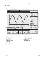
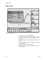
Ventilator screen
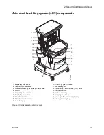
Figure 2-7 • Normal view
1. Alarm silence indicator and countdown clock
7. Total flow sensing (optional)
2. Alarm message areas
8. Ventilator settings
3. Waveform area
9. Mechanical ventilation status
4. Alarm limit settings
10. Ventilation mode
5. Measured values area
11. User message area
6. Circuit type
AC
.2
0.
004
Total
TV
ml
Vent On
RR
/min
I:E
Pmax
cmH2O
PEEP
cmH2O
More
Settings
VCV - Volume Control
Circle Fresh Gas Flow
l/min
O2
Air
N2O
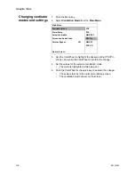
Push the knob to confirm the change. Turn the
knob to change the setting.
Time (sec)
Paw
O2% low
Ppeak
Pmean
Ppause
O2
%
TVexp
ml
MV
l/min
RR
/min
cmH2O
TVexp low
1
2
5
6
7
8
9
10
11
4
3
Содержание Aespire View
Страница 1: ...Aespire View User s Reference Manual Software Revision 6 X...
Страница 16: ...Aespire View 1 8 M1132382...
Страница 46: ...Aespire View 3 16 M1132382...
Страница 50: ...Aespire View 4 4 M1132382...
Страница 88: ...Aespire View 7 8 M1132382...
Страница 112: ...Aespire View 9 10 M1132382...
Страница 114: ...Aespire View 10 2 M1132382 System pneumatic circuits Figure 10 1 Pneumatic circuit diagram AC 20 001...
Страница 118: ...Aespire View 10 6 M1132382 Electrical block diagram Figure 10 2 Electrical block diagram AC 20 008...
Страница 137: ...10 Specifications and Theory of Operation M1132382 10 25 Figure 10 9 Gas composition related errors AB 74 027...
Страница 148: ...Aespire View I 4 M1132382...