10 Specifications and Theory of Operation
M1132382
10-23
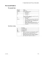
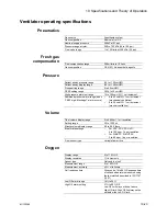
Ventilator operating specifications
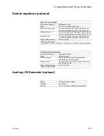
Pneumatics
Fresh gas
compensation
Pressure
Volume
Oxygen
Gas source
Anesthesia system
Gas composition
Medical air or O2
Nominal supply pressure
350 kPa (51 psi)
Pressure range at inlet
240 to 700 kPa (35 to 102 psi)
Flow valve range
1 to 120 l/min at 240 kPa (35 psi)
Flow compensation range
200 ml/min to 15 l/min
Gas composition
O2, N2O, Air, anesthetic agents
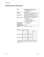
Patient airway pressure range
-20 to +120 cmH2O
Patient airway display range
-20 to +120 cmH2O
Pinsp setting range
5 to 60 cmH2O
PEEP setting range
Off, 4 to 30 cmH2O
High pressure alarm set range
12 to 100 cmH2O, 1 cm increment
Sustained pressure alarm range (when
‘PEEP high. Blockage?’ alarm occurs)
•
6 to 42 cmH2O, 1 cm increment
(mechanical ventilation)
•
6 to 30 cmH2O, 1 cm increment
(manual ventilation)
Tidal volume display range
5 to 9999 ml, 1 ml resolution
Setting range
20 to 1500 ml
Minute volume display range
0.0 to 99.9 liters
Breath rate settings
•
For VCV, PCV, PCV-VG:
4 to 100 bpm, 1 bpm resolution
•
For SIMV-PC, SIMV/PSV:
2 to 60 bpm, 1 bpm resolution
Flow sensor type
Variable flow orifice
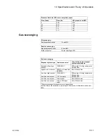
Display range
5 to 110% O2
Display resolution
1% increments
Sensor type
Galvanic fuel cell
Measurement range
0 to 100% O2
Measurement accuracy
± 3% of full scale
Cell response time
35 seconds, 10 to 90%. Response time
of cell and adapters is measured using
the test method described in ISO 7767
(1997)
Low O2 alarm range
18% to 99%
High O2 alarm setting
21% to 99%, Off
Low O2 limit may not be set above
High O2 limit. High O2 limit may not be
set below the Low O2 limit.
Содержание Aespire View
Страница 1: ...Aespire View User s Reference Manual Software Revision 6 X...
Страница 16: ...Aespire View 1 8 M1132382...
Страница 46: ...Aespire View 3 16 M1132382...
Страница 50: ...Aespire View 4 4 M1132382...
Страница 88: ...Aespire View 7 8 M1132382...
Страница 112: ...Aespire View 9 10 M1132382...
Страница 114: ...Aespire View 10 2 M1132382 System pneumatic circuits Figure 10 1 Pneumatic circuit diagram AC 20 001...
Страница 118: ...Aespire View 10 6 M1132382 Electrical block diagram Figure 10 2 Electrical block diagram AC 20 008...
Страница 137: ...10 Specifications and Theory of Operation M1132382 10 25 Figure 10 9 Gas composition related errors AB 74 027...
Страница 148: ...Aespire View I 4 M1132382...

