10 Specifications and Theory of Operation
M1132382
10-5
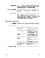
Mixed gas
The mixed gas goes from the flowmeter outlet through the vaporizer
that is ON, to the fresh gas outlet, and into the breathing system. A
pressure relief valve sets the maximum outlet pressure.
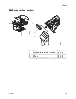
EZchange canister
When activated, this module permits continued ventilation and
rebreathing of exhaled gases without any gas passing through the
absorbent.
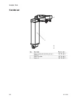
Condenser
The condenser removes water in the system that is produced from
the reaction of CO2 gas with the absorbent during low flow
anesthesia (fresh gas flows less than 1.5 l/min). The condenser is
connected between the outlet of the absorber canister and the inlet of
the circuit module. Moisture in the gas is condensed into water
droplets, which run into the condenser’s reservoir.
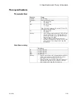
Pneumatic specifications
CAUTION
All gases supplied to the system must be medical grade.
Gas supplies
ACGO Port relief
Valve limits fresh gas pressure to 138 kPa (20 psi) at the flush flow.
Pipeline gases
O2, Air, N2O
Cylinder gases
•
O2, Air, N2O (maximum: 2 cylinders of
each gas) with 3 cylinders total.
•
1 cylinder maximum on pendant model
Cylinder connections
•
Pin indexed (all gases).
•
Nut and gland DIN-477 (O2, N2O, Air)
•
Large cylinder kit available for O2 and
N2O
Primary regulator output
pressure
•
Pin indexed: The primary regulator is set
to pressure less than 345 kPa (50 psi).
•
DIN-477: The primary regulator is set to
pressure less than 414kPa (60 psi).
Pressure-relief valve
Approximately 758 kPa (110 psi)
Pipeline connections
(filtered)
•
DISS - Male; DISS-Female; AS 4059
(Australian).
•
S90-116 (French Air Liquide)
•
BSPP 3/8 (Scandinavian) or NIST (ISO
5359).
•
All fittings available for O2, Air, and N2O.
Pressure displays
Color coded gauges
Pipeline inlet pressure
280-600 kPa (41-87 psi)
O2 supply failure alarm
193 to 221 kPa (28 to 32 psi)
N2O shutoff
3.5 kPa (0.5 psi)
Содержание Aespire View
Страница 1: ...Aespire View User s Reference Manual Software Revision 6 X...
Страница 16: ...Aespire View 1 8 M1132382...
Страница 46: ...Aespire View 3 16 M1132382...
Страница 50: ...Aespire View 4 4 M1132382...
Страница 88: ...Aespire View 7 8 M1132382...
Страница 112: ...Aespire View 9 10 M1132382...
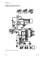
Страница 114: ...Aespire View 10 2 M1132382 System pneumatic circuits Figure 10 1 Pneumatic circuit diagram AC 20 001...
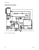
Страница 118: ...Aespire View 10 6 M1132382 Electrical block diagram Figure 10 2 Electrical block diagram AC 20 008...
Страница 137: ...10 Specifications and Theory of Operation M1132382 10 25 Figure 10 9 Gas composition related errors AB 74 027...
Страница 148: ...Aespire View I 4 M1132382...

