11
3.2 Multiple Cameras Cascade
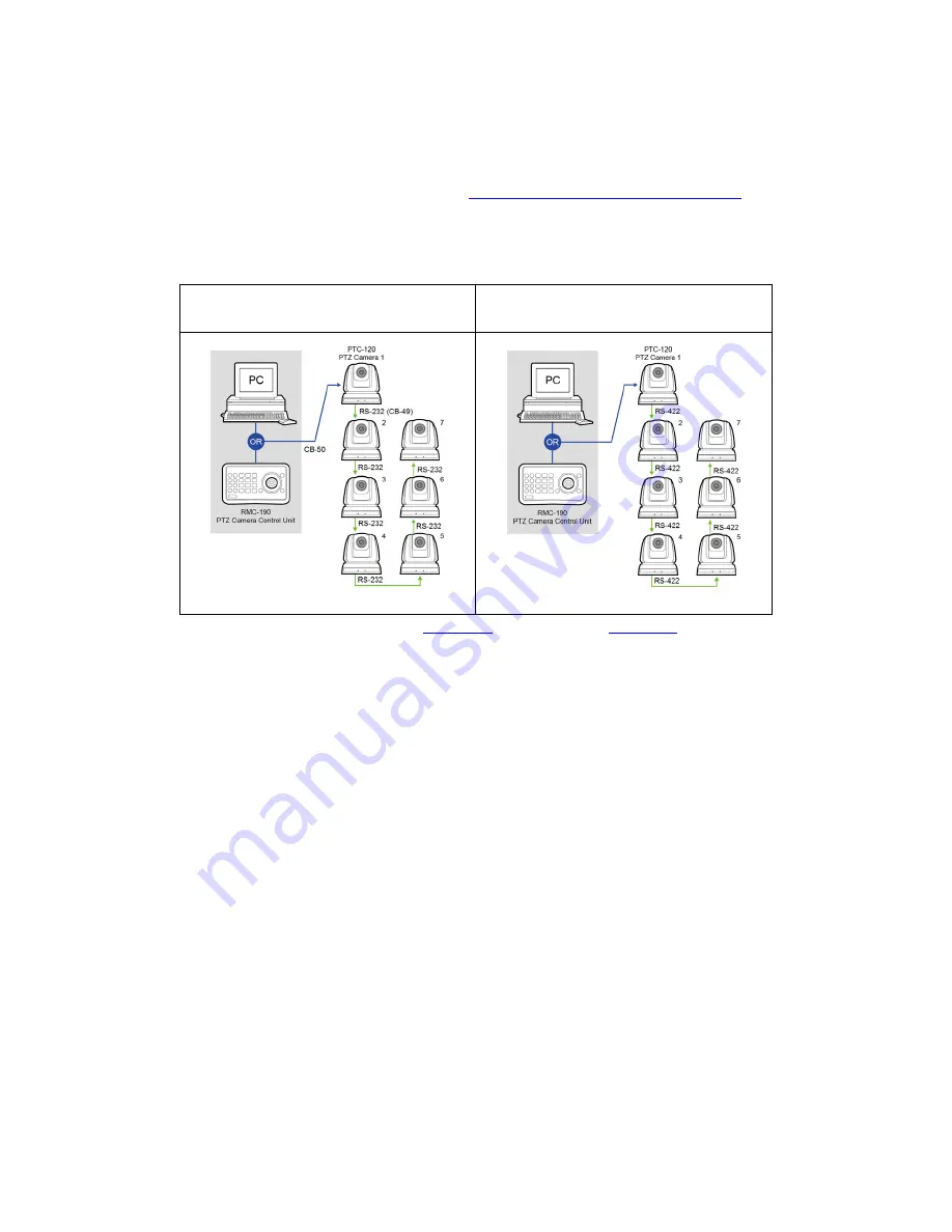
The PTC-120 camera can also be used in an environment where multiple cameras
are required. With RS-232 INPUT/OUTPUT ports, the user is allowed to cascade up
to seven cameras, which are subsequently controlled by either a computer (Please
download a utility program first from
http://www.serialporttool.com/PTZ.htm
in
case you need to control the camera via a PC) or a SONY VISCA compatible
controller. RS-232C and RS-422 system setups for connection of multiple cameras
are illustrated in the respective diagrams below.
RS-232C Cascade Connection
RS-422 Cascade Connection
For wiring information, please see
section 11
for RS-232C and
section 12
for RS-422.
However, the connection will be broken if one unit is powered off. In other words,
the cameras connected subsequent to the broken one will become uncontrollable
by RMC-190. For example, in the above diagram, if cameras #2 and #3 are defective
or powered off, all camera connections (4/5/6/7) after camera #3 will be cut off
from the daisy chain and RMC-190 will not be able to control them even if the
cameras are still operable.
The cameras have to be at least in the standby mode for the entire daisy chain
connection to stay controllable by RMC-190. In the above example, if cameras #2
and #3 are in standby mode, the user will still be able to control all cameras after
camera #3 from RMC-190.
If the camera is powered off or defective, there will be no LED lighting in standby
mode. The user should check the LED lighting first if the daisy chain is found to be
broken.
Содержание PTC-120
Страница 1: ...1 ...
Страница 14: ...14 16 Service Switch Page 43 Service switch is used to set the respective firmware upgrades ...
Страница 32: ...32 Metal plate A Machine Side Metal plate A Locking Screw Metal plate A Machine Side ...
Страница 35: ...35 Finally remove the screws on the hanger and the device ...
Страница 53: ...53 ...
Страница 62: ...62 Notes ...
Страница 63: ...63 Notes ...
Страница 64: ...64 15 Service Support ...


