background image


120 20191-001


 Paragon-III


 Technical Manual


17

Table 3 - Checklist A (After installation)

CHECKLIST A 

(

Paragon-III

Recommended Check out after Installation


Step 

ACTION 

EXPECTED RESULTS 

at 25

°

MEASURE WITH 

IF NOT? 

Normal Power-up  
Sequence 

BDLC-III beeps once, all LEDs come ON for about four seconds, the green 
LEDs then flash in a “ripple” pattern for close to two seconds. All LEDs go OFF 
except the CK that should flash 6 to 8 times per second.  

Connect and save unit 
config


Press CDip 

Get

 button 

as per CDip Help content 

Transmitter Output 
Power 

Press 

TXON (Unmod)


5

 watts


+0%, -10% 
 

Service monitor set 
to read power 
or 
10W in-line wattme-
ter installed as close 
as possible to the 
unit antenna con-
nector. 

Check for bad connections, 
damaged coax cable, etc. 

Transmitter Reflected 
Power 

Press 

TXON (Unmod)


< 5% of forward power or 
as specified by System 
Engineering.  

10W in-line wattme-
ter 

Check for bad connections, 
damaged coax cable, etc. 

RF Link test


Use the mobile address 
function and “Send” but-
ton to dynamically test 
the link 

Look for  

“Delivery confirmed” on 

the Status bar 

Refer to 4.3.1 and to 

CDip Help content. 

Mobile is out of  range 

Refer to factory technical 

support. 


Содержание Paragon-III

Страница 1: ...tion Technical Manual Version 0 02 preliminary The entire contents of this manual and the Radio Installation Software described in this manual are copyright 2004 by DATARADIO Inc Copyright DATARADIO Inc April 2004 Part no 120 20191 001 ...

Страница 2: ...mitter module 12 3 1 4 BDLC III module 13 3 1 5 Speaker panel 13 3 1 6 Dual Power Supply module 14 3 1 7 Radio Backplane Assembly 15 4 TROUBLE SHOOTING AND TESTING 16 4 1 EQUIPMENT REQUIRED 16 4 2 RECOMMENDED CHECKS 16 4 3 ADDITIONAL TEST DETAILS 20 4 3 1 RF Data Link Test 20 5 RADIO PROGRAMMING AND ADJUSTMENTS 21 5 1 SERIES II RADIO PROGRAMMING 21 5 1 1 Recommended Items 21 5 1 2 Module Programmi...

Страница 3: ...TEM INFORMATION SAMPLE 22 FIGURE 15 RECEIVER CHANNEL INFORMATION SAMPLE 22 FIGURE 16 EXCITER SYSTEM INFOMATION SAMPLE 23 FIGURE 17 EXCITER CHANNEL INFORMATION SAMPLE 23 FIGURE 18 BACKPLANE DIP SWITCHES EXAMPLE CHANNEL 1 SELECTED 24 FIGURE 19 T885 TYPICAL RSSI CURVE VOLT TO DBM 27 FIGURE 20 T885 0200 RECEIVER TUNING CONTROLS LOCATION 30 FIGURE 22 T881 0200 EXCITER TUNING CONTROLS LOCATION 31 TABLE ...

Страница 4: ...20191 002 Paragon III Technical Manual iv WHAT S NEW History Version 0 02 October 2004 issue 0 02 preliminary had appended data about 50W PA option Aethercomm Version 0 01 April 2004 first issue preliminary ...

Страница 5: ...E DTE Data Terminal Equipment This designation defines the direction input or out put of the various RS 232 interface signals Most user equipment as well as PCs are wired as DTE Gemini III High specs dual DSP mobile radiomodem with Dataradio PD technology Paral lel Decode IP Network Speed This is the bit rate on the RF link between units Could be different from COM port baud rate Paragon III Next ...

Страница 6: ...ations It features dual receivers for added data decode sensitivity in multi path and fading environments When used with Dataradio s state of the art Gemini III G3 mobile IP data solution the system delivers unequaled high speed data performance and unmatched effective throughput All Paragon III models are supplied in a rackmount configuration that includes A Paragon III full duplex Radio modem as...

Страница 7: ...rocess A 50 Watts Power Amplifier model is intended for future availability Models with on air data speeds and modulation types as follows Table 1 On air data speeds and modulation types Channel spacing Modulation type 50 kHz SRC4FSK 64 kb s SRC8FSK 96 kb s SRC16FSK 128 kb s Uses the Next generation high efficiency Dataradio Enhanced DBA over the air protocol Over the air compatible with Gemini II...

Страница 8: ...ional customers DATARADIO Inc 5500 Royalmount Ave suite 200 Town of Mount Royal Quebec Canada H4P 1H7 Technical support hours Monday to Friday 9 00 AM to 5 00 PM Eastern Time phone 1 514 737 0020 fax 1 514 737 7883 Email address support dataradio com or For U S customers DATARADIO Corp 6160 Peachtree Dunwoody RD suite C 200 Atlanta Georgia 30328 Technical support hours Monday to Friday 8 30 AM to ...

Страница 9: ...a question arise during servicing of the unit Customers are responsible for shipping charges for returned units Units in warranty will be repaired free of charge unless there is evidence of abuse or damage beyond the terms of the warranty Units out of warranty will be subject to service charges Information about these charges is available from Technical Support 1 6 Packaging Each Paragon III produ...

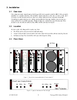
Страница 10: ... modem 2 2 Location Be sure to place the Paragon III in such a way that The LEDs can be seen as an aid in troubleshooting Access to the antenna connector and to the back connectors is possible without removing the unit Sufficient air may flow around the unit to provide adequate cooling 2 3 Front View Figure 1 Typical rack mount multi modules Radio Assembly Figure 2 Typical rack mount dual Power Su...

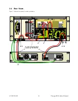
Страница 11: ...120 20191 002 Paragon III Technical Manual 6 2 4 Rear Views Figure 3 Base Station standard assembly preliminary 1 18 15 18 18 18 For Cable Assembly details see drawing 730 03439 002 RTB2 RTB1 ...

Страница 12: ...Technical Manual 7 Figure 4 Base Station standard assembly with 3rd party DC supply module preliminary For Cable Assembly details see drawing 730 03439 002 1 1 18 15 As required Third Party Power Supply 13 8VDC Nominal RTB2 RTB1 ...

Страница 13: ...us Both power supply modules are internally connected to ground via their individual rear connected seven foot standard 120 VAC power cords Nevertheless each requires a separate secure electrical ground connection Individual grounding tabs are provided next to the power connectors Similarly the Radio Assembly chassis requires a secure ground connection A threaded grounding binding post fitted with...

Страница 14: ...ff the cable DO NOT TWIST THE WIRE STRANDS Insert the DC cable into the screw terminal and tighten the screw to secure the cable as per the torque settings given below Torque Settings The manufacturer recommends torque setting all power supply terminal screws to 0 5 to 0 6 Nm or 4 5 to 5 3 In lb or to 37 to 44 ft lb Note Dataradio uses a Sturtuvan Richmond 29 pieces adjustable torque screwdriver m...

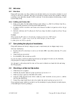
Страница 15: ...liers are NOT acceptable 2 7 Completing the physical Installation Paragon III products are factory configured to user s requirements and are shipped ready to run After new installations Re check that all connections are secure on the radio BDLC assemblies antennas PC power cords etc Check that fuses are inserted Turn both BDLC III and radio power ON You are now ready to check for normal operation ...

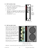
Страница 16: ...speaker1 Gate LED indicates the status of the mute circuit It is lit when a signal above the mute threshold is received1 Supply LED is lit when DC power is applied Fast Flashes when linked with PGM800Win Slow Flashes indicates VCO synthesizer out of lock Unequal Flashes indicates internal communication error Line Level Not used Monitor Volume The audio output delivers up to 1 watt to the speaker A...

Страница 17: ...front panel only has the grills for the input of the airflow used to cool the heat sink while it is not mechanically attached to the PA module The rear side of the PA module yields access to the screws that lock the module onto the base station frame and the 4 connectors of the PA module as follows N female RF output connector supplies 10 50W RF power for a fixed gain of 10dB over the input power ...

Страница 18: ... 5 Speaker panel The speaker panel is fitted with a four Ω speaker Both series of radio assemblies share the same front panel fitted with an RJ11 connector This connector is used to allow programming the radio from the front of the unit via a programming lead This feature is exclu sive to the Series II modules If the speaker panel needs to be removed a mirror programming port connector is provided...

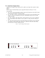
Страница 19: ... is are ON DC power is distributed to radio modules Flash green in conjunction with the OL LED flashing red when an over voltage condition is present Two Stby Standby voltage LED lights red when push button is off AC power is applied but DC is not distributed to radio modules To remove presence of voltage disconnect both power cords Two OL LEDs Monitor current overload light steady red when supply...

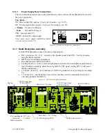
Страница 20: ...the Speaker panel front RJ11 Used for program ming the Radio modules DB 25F port to ancillary equipement One channel select DIP switch SW1 Cooling fan driver TB 3 located on backplane connects to the horizontally mounted fan on top of the Radio assembly and activated by BDLC s PTT signal setting JP1 2 3 will power the fan continuously 30 A Fuse F2 F3 two blade fuses 15ADC in parallel are used for ...

Страница 21: ...adequately warmed up This is particularly likely when field service is done during winter months 4 2 Recommended Checks A After an installation 1 LED Indications 2 Using CDip Save unit config to a file 3 Transmitter Output Power 4 Transmitter Reflected Power 5 RF Link test between Paragon III and mobile unit s B For annual maintenance trouble shooting Same checks as A plus 6 Carrier Frequency Erro...

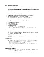
Страница 22: ...p Get button as per CDip Help content 3 Transmitter Output Power Press TXON Unmod 5 watts 0 10 Service monitor set to read power or 10W in line wattme ter installed as close as possible to the unit antenna con nector Check for bad connections damaged coax cable etc 4 Transmitter Reflected Power Press TXON Unmod 5 of forward power or as specified by System Engineering 10W in line wattme ter Check f...

Страница 23: ...Press TX ON Unmod 50 watts 0 10 Service monitor set to read power or 50W in line wattme ter installed as close as possible to the unit antenna connector Adjust Power on the front panel of the Power Amp 4 Transmitter Reflected Power Press TXON Unmod 5 of forward power or as specified by System Engineer ing 50 W in line wattmeter Check for bad connections damaged coax cable etc 5 Carrier Frequency E...

Страница 24: ...than 108 dBm including cable loss Typically 109 to 110 dBm Backplane correspond ing to the receiver be ing verified J1 RX1 or J5 RX2 Pin 6 see Figure 13 page 15 Service monitor IFR set to SINAD IFR IF filter set to MID position or 300 kHz wide filter Refer to section 5 2 2 9 Receiver distortion Dataradio wide band measurement method no audio filtering Set service monitor RF Gen output to 70 dBm De...

Страница 25: ... address range is 1 126 As an Alpha Mapped Nibble AMN address consisting of upper case letters in the range A P The valid address range is A to GN The base address is usually 1 The program may display one of the following messages on the status bar For Paragon III products address is not in AMN or number format For mobile products address is not in the range A GN In either case check that the addr...

Страница 26: ... Press and hold the Alt key while pressing at the same time the relevant hotkey as indicated by an underlined letter on the menu command On a drop down menu press only the hotkey without pressing the Alt key Use the Tab key to cycle available fields and the Enter key to validate entries E g Pressing Alt F opens the File drop down menu and pressing A opens the Save As directory service box Receiver...

Страница 27: ...120 20191 001 Paragon III Technical Manual 22 Figure 14 Receiver System Information Sample Figure 15 Receiver Channel Information Sample ...

Страница 28: ...120 20191 001 Paragon III Technical Manual 23 Figure 16 Exciter System Infomation Sample Figure 17 Exciter Channel Information Sample ...

Страница 29: ... its binary count is inactive The various DIP switch combinations of ON or OFF make up a binary total which identifies the channel number To select a channel set the appropriate DIP switch or switches to OFF to make the binary count total the channel number you want Set all other switches to ON Example To select channel 1 set the DIP switches as shown below Figure 18 Backplane DIP switches example...

Страница 30: ... wrench RF tuning trimming tools Extender Rail Kit for Series II chassis T800 13 0000 1x 6 coax cable N M to BNC M comes with the radio to connect the exciter to the PA 5 2 2 Receiver module Note 1 Refer to Figure 20 T885 Note 2 When the synthesizer is unlocked the front panel green LED called Supply will flash indicating that it needs re tuning Warning The LED will also flash when the unit is in ...

Страница 31: ...contact your Dataradio technical support WARNING Do NOT attempt to re tune the IF stages I e L300 and L301 for T885 These adjustments do not need to be re adjusted after frequency re programming Touching these coils will have a direct impact on the modem DSP ISI coefficient settings and may reduce signifi cantly the radio performances over data 5 2 2 4 SINAD and Linearity Check 1 Apply the followi...

Страница 32: ... test point location The following RSSI graphics are given as general information only Refer to factory technical support only if RX data performance degradation is noticed combined with something that does not look like those RSSI curves Figure 19 T885 Typical RSSI Curve volt to dBm 5 2 3 Exciter Module T881 xx 0200 Note 1 Refer to Figure 21 T881 Note 2 When the synthesizer is unlocked the front ...

Страница 33: ... channel All channels should lie within the upper and lower limits of 16V and 3V respectively for the T881 Note Normally the fast TX key option is installed and the synthesizer is always ener gized In the case where that option was not fitted key the transmitter by pressing the front panel Carrier button to make the above adjustment possible 5 2 3 3 TX Frequency Error Adjustment 1 Apply the follow...

Страница 34: ...Record deviation again 7 The difference in deviation between the two channels should be less than 300Hz If not re adjust IC220 to average the square wave shape on both channels until the spec is met 8 To confirm the adjustment select the active or the lowest frequency channel Compare the devia tion produced between 1000 Hz sine wave test tone and Random data test pattern The difference between the...

Страница 35: ...120 20191 001 Paragon III Technical Manual 30 Figure 20 T885 0200 Receiver Tuning Controls location ...

Страница 36: ...120 20191 001 Paragon III Technical Manual 31 Figure 21 T881 0200 Exciter Tuning Controls location ...

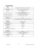
Страница 37: ...VAC TBD Channel spacing 50 kHz Operating Temperature Range 30 C to 60 C deleted power supply catalog number with 0 in second to last digit 10 C to 60 C with standard Dual Power Supply assy catalog number with 2 in second to last digit RECEIVER Selectivity 25 kHz 12 5 kHz 85 dB min 88 dB Typical 79 dB min 80 dB Typical Sensitivity 12 dB SINAD 116 dBm Spurious Response Rejection 100 dB Typical Inter...

Страница 38: ...nd Modulation type xRC16FSK 128 kb s xRC8FSK 92 kb s xRC4FSK 64 kb s Operating under Class I permissive change subset of 16 Level FSK FCC CERTIFICATIONS FCC IC DOC 762 764MHz and 767 773MHz EOTBDP3 T881 5W exciter T881 EOTBDP3 AET 50W PA option AET NA EMISSION DESIGNATORS Bit rate Baud rate Modulation 700MHz 128 kb s 32000 xRC16FSK 30K0F1D ...

Отзывы: