DI–710 Series and DI-715B Series Hardware Manual
Accessories
68
DI-5B45 Frequency Input Modules
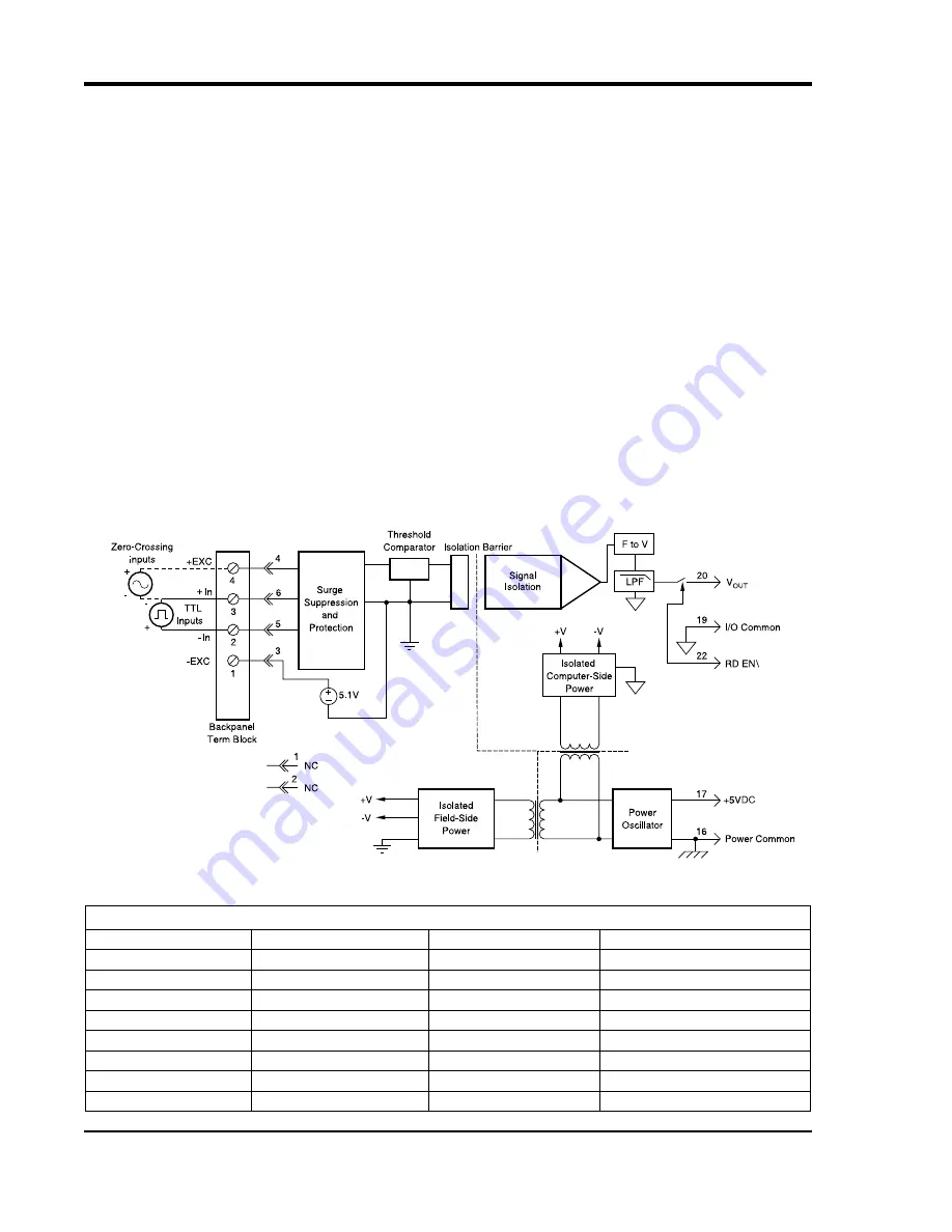
Each DI-5B45 frequency input module provides a single channel of frequency input which is isolated and converted
to a high level analog voltage output. This voltage output is logic switch controlled, which allows these modules to
share a common analog bus without the requirement of external multiplexers (see block diagram).
The frequency input signal can be a TTL level signal or a zero-crossing signal. Terminal 3 (+In) on the field-side ter-
minal block is the “common” or ground connection for input signals. A TTL signal is connected from terminal 2 (-In)
to terminal 3 (+In), while a zero-crossing signal is connected from terminal 4 (+EXC) to terminal 3 (+In). Input cir-
cuitry for each of the signal types has hysteresis built in. An input signal must cross entirely through the hysteresis
region in order to trigger the threshold comparator.
A 5.1V excitation is available for use with magnetic pickup or contact-closure type sensors. The excitation is avail-
able on pin 1 (-EXC) and the excitation common is pin 3 (+In).
The DI-5B modules are designed with a completely isolated computer side circuit which can be floated to ±50V from
Power Common, pin 16. This complete isolation means that no connection is required between I/O Common and
Power Common for proper operation of the output switch. If desired, the output switch can be turned on continuously
by simply connecting pin 22, the Read-Enable pin to I/O Common, pin 19.
A special circuit in the input stage of the module provides protection against accidental connection of power-line
voltages up to 240VAC.
Ordering Information
MODEL
INPUT RANGE
OUTPUT RANGE
EXCITATION
DI-5B45-01
0 to 500Hz
0 to +5V
+5.1Vdc @ 8mA
DI-5B45-02
0 to 1kHz
0 to +5V
+5.1Vdc @ 8mA
DI-5B45-03
0 to 3kHz
0 to +5V
+5.1Vdc @ 8mA
DI-5B45-04
0 to 5kHz
0 to +5V
+5.1Vdc @ 8mA
DI-5B45-05
0 to 10kHz
0 to +5V
+5.1Vdc @ 8mA
DI-5B45-06
0 to 25kHz
0 to +5V
+5.1Vdc @ 8mA
DI-5B45-07
0 to 50kHz
0 to +5V
+5.1Vdc @ 8mA
DI-5B45-08
0 to 100kHz
0 to +5V
+5.1Vdc @ 8mA
Содержание DI-710 Series
Страница 2: ......
Страница 4: ......
Страница 6: ......
Страница 10: ......
Страница 14: ......
Страница 18: ......
Страница 30: ......
Страница 48: ......
Страница 49: ...DI 710 Series and DI 715B Series Hardware Manual Block Diagram 39 6 Block Diagram DI 710 Models...
Страница 82: ......
Страница 83: ......


