Dataq DI-1000TC Скачать руководство пользователя страница 19

DI–1000TC User Manual

Module Configuration Software

13

4. Module Configuration 

Software

The following is a brief overview of how to get started with the DI-1000 Configuration Software.  A detailed expla-
nation of the configuration software is provided in the help files within the configuration program.

More than likely, you will not need to use the configuration software; it is only necessary when you wish to change 
the Baud Rate you will communicate at (the default Baud Rate is 9600), or - if you have multiple instruments that 
were shipped separately - to change the modules' addresses.  If you want to change the Baud Rate or if you have mul-
tiple devices daisy-chained together, you must run the configuration software.

When you install software from The W

IN

D

AQ

 Resource CD, The configuration software (config.exe) is downloaded 

in the same directory as W

IN

D

AQ

 in your Start > Programs menu.  To configure your device(s):
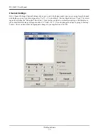
1.

Connect the device to your PC and then run the configuration software.  When the initial screen comes up, select 
Configure > Port or click on the Port icon.  Then select the port you are connected to.  

Note:  When using a USB 

Port it is important to know that Windows automatically assigns a Port that is not necessarily the next Port avail-
able on your PC.  To find out what Port has been assigned to your USB module check your Windows Device 
Manager or try assigning a Port until you get the correct one.
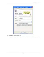
2.

To set your Baud Rate and your Address, select Configure > Setup or click on the Setup icon.  Here you can set 
your Baud Rate and your Address.  This must be done 

separately

 for each device.  Note that they all must have 

the same Baud Rate and the addresses must be synchronized (see below).  

Note:  Each device must be connected 

and configured separately - before daisy chaining.  Changes take effect when power is re-applied to the instru-
ment (i.e., you must disconnect and reconnect power for changes to take effect).

Setting up Addresses for Your Devices

The default address for all devices is 1.  This is the address for the master device.  You can leave it at this address if 
you are only running one device.  If you take a networked group of instruments and wish to run them all separately, 
you must change their addresses to 1 (the Master address).  If you then wish to re-create the network (or create a new 
network), you will need to change the addresses for all devices except the master.  This is done in the Setup window 
of the Configuration Software.  Each device beyond the master should be numbered sequentially (2, 3, 4, etc.).  Each 
device must be connected individually to set up its address.  In the Setup window, you will have to enter the desired 
address for the device you are configuring, the address of the master, and the address of the previous device on the 
chain.  See the diagram below for an example.

The use of master and previous addresses for each DI-1000 module allows the modules to synchronize their acquired 
readings. Essentially, the master paces the data acquisition scan rate, and each slave follows suit. A typical sequence 
is as follows:

Note:

  All modules’ addresses are pre-configured direct from the factory.  Setting addresses is only 

necessary when changing the configuration of your network (i.e., adding or (re)moving instruments).

Master

Slave 1

Slave 3

Slave 2

Address: 1
Previous: 1
Master: 1

Address: 2
Previous: 1
Master: 1

Address: 3
Previous: 2
Master: 1

Address: 4
Previous: 3
Master: 1

Содержание DI-1000TC

Страница 1: ...herwise without expressed written authorization from the com pany The distribution of this material outside the company may occur only as authorized by the company in writing DATAQ Instruments hardwar...

Страница 2: ......

Страница 3: ...products that have been repaired or altered by persons other than DATAQ Instru ments employees or products that have been subjected to misuse neglect improper installation or accident DATAQ Instrument...

Страница 4: ......

Страница 5: ...er to the DI 1000TC Instrument 5 Connecting the DI 1000TC Instrument to your Computer 5 RS 422 Interface Port Pin Out 6 Adapters 6 DI 1000TC Instrument Controls and Indicators 6 DI 1000TC Instrument F...

Страница 6: ......

Страница 7: ...1000TC s 1000VDC and Peak AC input to output and channel to channel isolation allows grounded TC measurements High Accuracy and Resolution Design Allows sharpened decisions with an overall accuracy o...

Страница 8: ......

Страница 9: ...n configuration Cold Junction Compensation Range 40 to 80 C Linearization Accomplished transparently by the software driver to deliver scaled tem perature values to the host program Input Impedance 1M...

Страница 10: ...in the field Supported Baud Rates 4800 9600 default 19200 38400 56800 115200 Data Bits 8 Stop Bits 1 Parity None Protocol ModBus ASCII Connector RJ 45 Pinout is as follows 1 Receive 2 Receive 3 XMIT 6...

Страница 11: ...wer to your DI 1000 Series instrument 1 Plug the DC power plug end of the power adapter cable into the DC power jack labeled POWER on the rear panel of the instrument There are two identical jacks eit...

Страница 12: ...000TC Instrument Controls and Indicators The following describes the user accessible items on the DI 1000TC Series instruments DI 1000TC Instrument Front Panel The DI 1000TC units are provided in 4 or...

Страница 13: ...if you would like to provide your own power source Installing the Software The software required to display and record data from the DI 1000TC can be easily installed directly from the WINDAQ Resource...

Страница 14: ...specify a destination or group window in the Start Menu for WinDaq software icons It is recommended that you accept the default 15 In the Installation Option dialog box specify whether you want all u...

Страница 15: ...are disconnected Click OK to continue 12 Connect the DI 1000 USB adapter to your computer s USB Port using the supplied cable 13 Connect the DI 1000TC to the DI 1000 USB adapter using a patch cable 1...

Страница 16: ...or each device incrementing Address and Previous Device by one for each subsequent instrument Each unit must be powered down after changing the device address or baud rate Master should always be 1 an...

Страница 17: ...DI 1000TC User Manual Getting Started 11 d Click OK to close the Properties dialog box Your distributed synchronous data acquisition system for thermocouple measurements is installed and ready to run...

Страница 18: ......

Страница 19: ...ice Note that they all must have the same Baud Rate and the addresses must be synchronized see below Note Each device must be connected and configured separately before daisy chaining Changes take eff...

Страница 20: ...ens for the module having a base address equal to the value programmed into it as Previous Address to send its data to the network After it detects that the module with Previous Address has sent its d...

Страница 21: ...sample rate per channel For example if you enter 5 as your sample rate per channel and you have all 8 channels enabled your current sample rate samples per sec ond would be 40 samples per channel tim...

Страница 22: ...want your data to appear in F or C C is the default You can toggle between F and C by select ing and deselecting the Fahrenheit check box Once you have selected your thermocouple type that thermocou p...

Страница 23: ...d be selected across from the 2 in the Addr column on the right of the window These channels are labeled 9 16 and they correspond with 1 8 on your device For example if you wanted to select channels 1...

Страница 24: ...han one device The section after the colon is an annota tion for the channel you have selected For example you may be comparing multiple engines in different locations You may want to label your first...

Страница 25: ......

Страница 26: ...41 Springside Drive Akron Ohio 44333 Telephone 330 668 1444 Fax 330 666 5434 E mail support dataq com Direct Product Links click on text to jump to page Data Acquisition Data Logger Chart Recorder The...

Отзывы: