background image

TC1100 

112 


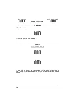
NOTE 

Since Test Mode is basically a diagnostic mode, it can 

only

 be 

enabled at run time and not saved to a non-volatile memory. 
For the same reason, this operating mode must be disabled 

only

 via RS232 interface by selecting another Operating Mode 

command, if you want to restore the previous state of the 
reader. 


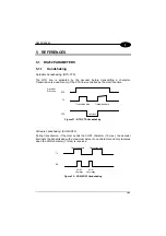
5.5.2 

Reads per Cycle 

 
In general, a 

reading cycle

 corresponds to the Phase ON / Phase OFF times of a 

device. 
The resulting effects of this parameter on code reading depend on other related 
configuration conditions. Here are the definitions of Phase ON and Phase OFF times. 
 
When 

one read per cycle

 is selected, the device decodes only one code during the 

Phase ON period and immediately turns to the Phase OFF. It is only possible to read 
another code when the next Phase ON time occurs. 
 
In 

multiple reads per cycle

, the Phase ON period is extended so that the device 

can continue decoding codes until an OFF event occurs. 


5.6 DECODING 

PARAMETERS 


CAUTION 

These parameters are intended to enhance the decoding capability 
of the reader for particular applications. Used incorrectly, they can 
degrade the reading performance or increase the possibility of a 
decoding error. 


5.6.1 Ink-Spread 

 
The ink-spread parameter allows the decoding of codes which are not perfectly 
printed because the page texture tends to absorb the ink. 


Содержание TC1100

Страница 1: ...TC1100 Installation Manual ...

Страница 2: ...TC1100 Reference Manual ...

Страница 3: ...TC1100 REFERENCE MANUAL ...

Страница 4: ...ts without prior notification Datalogic shall not be liable for technical or editorial errors or omissions contained herein nor for incidental or consequential damages resulting from the use of this material Product names mentioned herein are for identification purposes only and may be trademarks and or registered trademarks of their respective companies Datalogic S p A 2000 2004 821000702 Rev B ...

Страница 5: ...nputs 7 Outputs 8 External Beeper Connection 9 2 2 TC1100 CCD Scan Engine 10 2 2 1 Mechanical Installation 10 2 2 2 Electrical Connections 11 RS232 Interface 12 WEDGE Interface 12 PEN Emulation Interface 13 Inputs 13 Outputs 14 External Beeper Connection 15 2 3 Positioning 16 2 4 GFC TC1100 Accessory 17 3 SOFTWARE CONFIGURATION STRINGS 20 3 1 Default Configuration 20 3 2 TC1100 Configuration 22 Co...

Страница 6: ... 52 PEN EMULATION 53 Operating Mode 54 Minimum Output Pulse 55 Conversion To Code 39 56 Overflow 57 Output Level 57 Idle Level 58 Inter Block Delay 58 DATA FORMAT 59 Code Identifier 62 Custom Code Identifier 63 Header 64 Terminator 65 Field Adjustment 66 Field Adjustment Character 67 Code Length Tx 67 Character Replacement 68 No Read Character 70 POWER SAVE 71 Read Rate 72 Sleep State 72 Enter Sle...

Страница 7: ...odablock A 96 Codablock F 96 MSI 97 Plessey 98 Telepen 99 Delta IBM 100 Code 49 101 Pharmacode 101 PDF417 102 5 REFERENCES 103 5 1 RS232 Parameters 103 5 1 1 Handshaking 103 5 1 2 ACK NACK from Host Protocol 104 5 1 3 FIFO 104 5 1 4 RX Timeout 104 5 2 Pen Parameters 105 5 2 1 Minimum Output Pulse 105 5 2 2 Overflow 105 5 2 3 Output and Idle Levels 106 5 2 4 Inter Block Delay 106 5 3 Data Format 10...

Страница 8: ...rating Modes 110 5 5 2 Reads per Cycle 112 5 6 Decoding Parameters 112 5 6 1 Ink Spread 112 5 6 2 Overflow Control 113 5 6 3 Interdigit Control 113 5 7 Configuration Editing COmmands 113 6 TECHNICAL FEATURES 114 Reading Diagrams 115 A CODE IDENTIFIER TABLE 117 B HEX AND NUMERIC TABLE 121 ...

Страница 9: ... command strings to the TC1100 and Help On Line to explain configuration parameters This manual contains the complete set of command strings for TC1100 configuration These strings must be sent via the RS232 interface using a terminal emulator such as HyperTerminal or with the WinHost Terminal Configurations can also be sent as batch files Refer to paragraph 3 2 for configuration procedures 1 1 2 C...

Страница 10: ...describing the operation of the more complex parameters are given in chapter 5 1 2 STATUS INDICATORS The reader has two LED indicators signaling several operating conditions which are described in the tables below TC1100 Scanner Led2 Led1 TC1100 Scan Engine POWER UP POWER ON LED2 Meaning ON Power supply ON OFF Power supply OFF DATA ENTRY GOOD READ LED1 Meaning ON Good read LED1 will remain ON unti...

Страница 11: ...ard to the following characteristics Barcode type Enclosure The following models are therefore available TC1100 0100 CCD Scan Engine for linear codes TC1100 0200 CCD Scan Engine for linear and PDF417 codes TC1100 1100 CCD Scanner for linear codes TC1100 1200 CCD Scanner for linear and PDF417 codes ...

Страница 12: ...hanical Installation The diagram below gives the overall dimensions of the reader and may be used for its installation 54 2 13 7 6 0 30 30 5 1 20 31 6 1 25 24 0 94 9 5 0 37 10 4 0 41 70 7 2 78 68 6 2 70 mm in 17 7 0 70 Optical Axis Figure 1 Overall Dimensions ...

Страница 13: ...n Connector 1 Shield earth ground 2 TX transmit data 3 RX receive data 4 RTS request to send 5 CTS clear to send 6 nc not connected 7 SGND signal ground 8 EXT BEEPER external beeper connection 9 VCC 5 Vdc 10 nc not connected 11 OUT 12 OUT see Figure 10 13 VCC 5 Vdc 14 nc not connected 15 nc not connected 16 nc not connected 17 nc not connected 18 EXT TRIG 19 EXT TRIG See Figures 6 to 9 20 DATAIN_W...

Страница 14: ...5 pin 7 4 5 3 SGND RTS CTS RX TX 2 Host SGND DCD DTR TXD RXD Earth Ground Figure 3 RS232 Interface Connection to Host WEDGE Interface The TC1100 Scanner can communicate with the Host in a WEDGE Interface Keyboard Emulation using the signals provided on the 25 pin connector The pins are indicated in Table 1 and in the following diagram TC1100 25 pin 20 DATAIN 24 CLKOUT 21 DATAOUT 25 GND VCC 13 Host...

Страница 15: ...s always advisable to use shielded cables Inputs There is an input available on the TC1100 Scanner relative to the External Trigger The pins are indicated in Table 1 These inputs are optocoupled and can be driven by both an NPN or PNP type command The connections are indicated in the following diagrams EXT TRIG 18 19 5V TC1100 EXTERNAL TRIGGER Signal V 30 Vdc max Vext EXT TRIG Figure 6 Input NPN C...

Страница 16: ...cc 5Vdc 13 25 GND Ground V Signal EXT TRIG EXT TRIG Figure 9 Input PNP Command Using TC1100 Power Outputs There is an output available on the TC1100 Scanner relative to the Good Read event The pins are indicated in Table 1 The connections are indicated in the following diagram USER INTERFACE Vext 40 Vdc max OUT 11 12 OUT TC1100 Figure 10 Output Connection Good Read Example NPN ...

Страница 17: ...e built is shown in the schematic diagram below 5 Vdc pin 13 5 Vdc pin 13 R2 10K R1 1K Q1 BC337 BZ1 see below D1 1N4148 GND pin 25 BEEPER pin 8 Figure 11 TC1100 Scanner Beeper Connection The following list indicates several piezoelectric buzzers that can be used in the circuitry above part BZ1 Manufacturer Type MURATA PKB30SPC 2001 3001 DIGISOUND F TCW05 CITIZEN MEB 12C 5 BUJEON BS12 A See chapter...

Страница 18: ...e overall dimensions of the TC1100 Scan Engine and may be used for its installation 12 2 0 48 25 7 1 01 63 2 48 Veritcal Optical Axis 28 5 1 12 63 2 48 2 5 0 10 57 2 24 2 5 0 10 60 5 2 38 2 5 0 10 50 1 97 18 0 71 Ø2 7 Ø0 11 n 4 40 5 1 59 Horizontal Optical Axis mm in Figure 12 Overall Dimensions ...

Страница 19: ...ctor pins are indicated in the following table J2 J1 1 1 Figure 13 8 pin Connectors J1 1 SGND signal ground 2 OUT 3 OUT see Figure 21 4 EXT BEEPER beeper output signal 5 CTS clear to send 6 RX receive data 7 RTS request to send 8 TX transmit data J2 1 VCC 5 Vdc 2 GND power ground 3 CLKOUT 4 DATAOUT 5 DATAIN_WAND 6 CLKIN 7 EXT TRIG 8 EXT TRIG See Figures 17 to 20 Table 2 TC1100 Scan Engine Pinout ...

Страница 20: ...C1100 1 7 5 6 SGND RTS CTS RX TX 8 Host SGND DCD DTR TXD RXD Earth Ground J1 Figure 14 RS232 Interface Connection to Host WEDGE Interface The TC1100 Scan Engine can communicate with the Host in a WEDGE Interface Keyboard Emulation using the signals provided on the J2 connector The pins are indicated in Table 1 and in the following diagram TC1100 5 DATAIN 3 CLKOUT 4 DATAOUT 2 GND VCC 1 J2 6 CLKIN H...

Страница 21: ...ation Interface Connection to Host Inputs There is an input available on the TC1100 Scan Engine relative to the External Trigger The pins are indicated in Table 2 These inputs are optocoupled and can be driven by both an NPN or PNP type command The connections are indicated in the following diagrams EXT TRIG 7 8 5V TC1100 EXTERNAL TRIGGER Signal V 30 Vdc max Vext EXT TRIG J2 Figure 17 Input NPN Co...

Страница 22: ...Vdc 1 2 GND Ground V Signal EXT TRIG EXT TRIG J2 Figure 20 Input PNP Command Using TC1100 Power Outputs There is an output available on the TC1100 Scan Engine relative to the Good Read event The pins are indicated in Table 2 The connections are indicated in the following diagram USER INTERFACE Vext 40 Vdc max OUT 3 2 OUT TC1100 J1 Figure 21 Output Connection Good Read Example NPN ...

Страница 23: ...ilt is shown in the schematic diagram below 5 Vdc J2 pin 1 5 Vdc J2 pin 1 R2 10K R1 1K Q1 BC337 BZ1 see below D1 1N4148 GND J2 pin 2 BEEPER J1 pin 4 Figure 22 TC1100 Scan Engine Beeper Connection The following list indicates several piezoelectric buzzers that can be used in the circuitry above part BZ1 Manufacturer Type MURATA PKB30SPC 2001 3001 DIGISOUND F TCW05 CITIZEN MEB 12C 5 BUJEON BS12 A Se...

Страница 24: ...hree ideal label position angles Pitch 0 Skew 10 to 30 and Tilt 0 Follow the suggestions for the best orientation The Pitch angle is represented by the value P in Figure 23 Position the reader in order to minimize the Pitch angle Figure 23 Pitch Angle The Skew angle is represented by the value S in Figure 24 Position the reader to assure at least 10 for the Skew angle This avoids direct light refl...

Страница 25: ...in order to minimize the Tilt angle Figure 25 Tilt angle 2 4 GFC TC1100 ACCESSORY The GFC TC1100 is an 80 deflection mirror that is mounted directly to the TC1100 Scanner or Scan Engine Figure 26 GFC TC1100 The overall dimensions are provided in the figure below and can be used for its mounting T ...

Страница 26: ...9 20 0 79 20 0 79 10 0 39 4 5 0 18 84 5 3 33 Figure 27 GFC TC1100 Overall Dimensions To fix a TC1100 1xx Scanner to the GFC TC1100 use the 4 M 2 5x5 mm screws supplied with the GFC Kit Refer to the figure below Figure 28 Fixing TC1100 Scanner to GFC TC1100 ...

Страница 27: ...ts supplied with the GFC Kit Refer to the figure below Figure 29 Fixing TC1100 Scan Engine to GFC TC1100 The 80 deflection mirror assures that the minimum skew angle is maintained to avoid direct light reflection which can degrade reading performance 5 0 80 10 Code Surface TC1100 0x00 or TC1100 1x00 Figure 30 Maintaining Minimum Skew Angle ...

Страница 28: ...e 39 disabled output level normal idle level normal minimum output pulse 600 µs overflow medium inter block delay disabled DATA FORMAT Code identifier disabled field adjustment disabled code length TX disabled character replacement disabled header STX terminator CR LF no read character CAN POWER SAVE 270 read sec sleep disabled standby disabled READING PARAMETERS On Line mode beeper intensity high...

Страница 29: ... Check digit transmitted no conversions Code 39 variable length code 1 99 characters Code 128 Check digit not transmitted variable length code 1 99 characters PDF417 TC1100 x200 only disabled codes EAN 128 ISBT128 Code 93 Codabar pharmaceutical codes Delta IBM Code 16K Code 49 MSI Plessey Telepen Pharmacode only TC1100 x100 Codablock A Codablock F Standard and EAN only TC1100 x200 ...

Страница 30: ...e PC serial port to the TC1100 default RS232 communication parameters 2 Using a Terminal Emulation Program send the Restore Default string to the reader using the syntax described on the next page 3 Send all the necessary command strings according to your application s requirements CAUTION The WEDGE or PEN Emulation interface selections must be sent last since they will cause the reader to no long...

Страница 31: ...atrix 2 5 3 bars no check digit variable length code from 1 to 32 characters Enter configuration environment Multiple command programming sequence Each configuration parameter setting removes the condition previously active for that parameter NOTE The device buffer can contain about 400 characters If your programming string goes over this value you must split it into separate groups and send each ...

Страница 32: ...ls 31xx 32xx 34xx 37xx make break keyboard CP501 for IBM Terminals 31xx 32xx 34xx 37xx make only keyboard CP502 typewriter FK0 Keyboard Type for IBM Terminals 31xx 32xx 34xx 37xx advanced FK1 for IBM XT CP503 for IBM Terminal 3153 CP504 for IBM PC Notebook CP505 for IBM SURE1 CP506 for IBM AT ALT mode CP507 for IBM PC Notebook ALT mode CP508 for Wyse Terminal ANSI Keyboard CP509 for Wyse Terminal ...

Страница 33: ... Data bits 7 CA0 8 CA1 9 CA2 Stop bits 1 CB0 2 CB1 Handshaking disable CE0 RTS CTS CE1 XON XOFF CE2 RTS always On CE3 ACK NACK Protocol disable CF0 enable CF3 FIFO disable EC0 enable EC1 Inter character delay ms CK00 CK99 RX Timeout 100 ms CL00 CL99 WEDGE DESCRIPTION STRING Keyboard nationality Belgian FJ7 English FJ4 French FJ2 German FJ3 Italian FJ1 Spanish FJ6 Swedish FJ5 USA FJ0 ...

Страница 34: ...rl Key FO1 PEN DESCRIPTION STRING Operating mode interpret does not require or transparent does not require or Minimum output pulse 200µs DG0 400µs DG1 600µs DG2 800µs DG3 1 ms DG4 1 2 ms DG5 Conversion to Code 39 disable conversion to Code 39 DA0 enable conversion to Code 39 DA1 Output level normal DD0 inverted DD1 Idle level normal DE0 inverted DE1 Overflow narrow overflow DH0 medium overflow DH...

Страница 35: ...tor EA10 one character EA11x two characters EA12xx three characters EA13xxx four characters EA14xxxx five characters EA15xxxxx six characters EA16xxxxxx seven characters EA17xxxxxxx eight characters EA18xxxxxxxx No Read Character disable EP0 enable EP1x a ASCII character b c x HEX values representing an ASCII character a ASCII character of the DATALOGIC STANDARD Code Identifier from the table on p...

Страница 36: ...d character replacement EO3afg a ASCII character d a number from the Hex Numeric Table e f g HEX values representing an ASCII character a ASCII character of the DATALOGIC STANDARD Code Identifier from the table on page 60 d a number in the range 01 32 from the Hex Numeric Table e Hex value from 00 to FE f Hex value of the character to be replaced from 00 to FE g Hex value of the new character to i...

Страница 37: ... Tone 4 BH3 Beeper Type monotone BJ0 bitonal BJ1 Beeper Length long BI0 short BI1 PDF Decoding Recognition low BW0 Intensity high BW1 DECODING PARAMETERS DESCRIPTION STRING Ink Spread disable AX0 enable AX1 Overflow Control disable AW1 enable AW0 Interdigit Control disable AV0 enable AV1 Puzzle SolverTM disable AU0 enable AU1 Decoding Safety one read ED0 two reads ED1 three reads ED2 four reads ED...

Страница 38: ...AP1 enable ISSN AP2 enable ISBN and ISSN AP3 ISBN Conversion codes disable ISBN and ISSN AP0 Code 39 disable Code 39 family AB0 Standard no check digit control AB11 check digit control and transmission AB12 check digit control without transmission AB13 Full ASCII no check digit control AB21 check digit control and transmission AB22 check digit control without transmission AB23 CIP 39 AB3 Code 32 A...

Страница 39: ...43xxxx CIP HR AC5 Codabar disable Codabar family AD0 Standard no start stop character equality control nor transmission AD111 no start stop character equality control but transmission AD112 start stop character equality control but no transmission AD121 start stop character equality control and transmission AD122 ABC Codabar no start stop character equality control but transmission AD212 Codabar A...

Страница 40: ...e Standard AN1 enable EAN AN2 MSI disable the family AE0 TC1100 x100 only no check AE1 MOD10 no tx AE2 MOD10 with tx AE3 MOD11 MOD10 no tx AE4 MOD11 MOD10 with tx AE5 MOD10 MOD10 no tx AE6 MOD10 MOD10 with tx AE7 Plessey disable the family AF0 TC1100 x100 only Standard no check AF11 Standard check with tx AF12 Standard check no tx AF13 Anker no check AF21 Anker check with tx AF22 Anker check no tx...

Страница 41: ...R0 TC1100 x200 only enable AR1 Pharmacode disable AQ0 TC1100 x100 only forward code TX direction AQ1xxyy reverse code TX direction AQ2xxyy overflow ratio AQAzz xx ASCII numbers that define the minimum acceptable code length yy ASCII numbers that define the maximum acceptable code length The minimum code length is 2 characters The maximum code length is 16 characters zz ASCII numbers that define th...

Страница 42: ... INITIAL SETUP The following procedure allows preparing your TC1100 to read barcodes by using the default settings RESTORE DEFAULT 1 Read the restore default parameters code below Restore TC1100 Default i Pk i Pk i Pk INTERFACE SELECTION 2 Read the interface selection code for your application RS232 i 1 k i 1 k i 1 k PEN i 1 k i 1 k i 1 k ...

Страница 43: ...BARCODE CONFIGURATION 35 4 WEDGE IBM AT or PS 2 PCs i 1 Bk i 1 Bk i 1 Bk IBM XT i 1 Wk i 1 Wk i 1 Wk PC Notebook i 1 ek i 1 ek i 1 ek IBM SURE1 i 1 k i 1 k i 1 k IBM Terminal 3153 i 1 k i 1 k i 1 k ...

Страница 44: ...M Terminals read the correct KEY TRANSMISSION code Select the KEYBOARD TYPE if necessary default advanced keyboard KEY TRANSMISSION MODE make only keyboard i 1 Pk i 1 Pk i 1 Pk make break keyboard i 1 Ik i 1 Ik i 1 Ik KEYBOARD TYPE advanced keyboard i fk i fk i fk typewriter keyboard i ak i ak i ak ...

Страница 45: ...lity used You do not need to make a Keyboard Nationality selection default Num Lock Unchanged Make sure the Num Lock key on your keyboard is ON IBM AT ALT mode i 1 k i 1 k i 1 k PC Notebook ALT mode i 1 k i 1 k i 1 k WYSE TERMINALS ANSI Keyboard i 1 k i 1 k i 1 k PC Keyboard i 1 Hk i 1 Hk i 1 Hk ASCII Keyboard i 1 Ok i 1 Ok i 1 Ok VT220 style Keyboard i 1 dk i 1 dk i 1 dk ...

Страница 46: ...100 38 4 WEDGE continued DIGITAL TERMINALS VT2xx VT3xx VT4xx i 1 Vk i 1 Vk i 1 Vk APPLE APPLE ADB Bus i 1 k i 1 k i 1 k YOUR READER IS NOW READY TO READ BARCODES To change the default settings see par 4 2 ...

Страница 47: ...roup The first three groups are for Standard Interface parameter configuration RS232 WEDGE PEN EMULATION The following parameter groups are common to all interface applications DATA FORMAT parameters regard the messages sent to the Host system for all interfaces except Pen Emulation POWER SAVE manages overall current consumption in the reading device READING PARAMETERS control various operating mo...

Страница 48: ...ER CHARACTER DELAY RX TIMEOUT 1 Read the Enter Configuration code ONCE available at the top of each page 2 Read configuration codes from the desired groups Read the code and follow the procedure given Default value 3 Read the Exit and Save Configuration code ONCE available at the top of each page ...

Страница 49: ...onfiguration i k i k 41 BAUD RATE 150 baud i 6k i 6k i 6k 300 baud 600 baud i 9k i 9k i 9k i k i k i k 1200 baud 2400 baud i k i k i k i Bk i Bk i Bk 4800 baud 9600 baud i Ek i Ek i Ek i Hk i Hk i Hk 19200 baud 38400 baud i Kk i Kk i Kk i Nk i Nk i Nk ...

Страница 50: ...uration i k i k RS232 Exit and Save Configuration i k i k 42 PARITY none i 4k i 4k i 4k even parity i 7k i 7k i 7k odd parity i k i k i k DATA BITS 7 bits i 0k i 0k i 0k 8 bits i 3k i 3k i 3k 9 bits i 6k i 6k i 6k ...

Страница 51: ...d Save Configuration i k i k 43 STOP BITS 1 stop bit i 2k i 2k i 2k 2 stop bits i 5k i 5k i 5k HANDSHAKING disable i 8k i 8k i 8k hardware RTS CTS i k i k i k software XON XOFF i k i k i k RTS always ON i Ak i Ak i Ak See par 5 1 1 for details ...

Страница 52: ...ion i k i k RS232 Exit and Save Configuration i k i k 44 ACK NACK PROTOCOL disable i k i k i k enable i Ck i Ck i Ck See par 5 1 2 for details FIFO disable i 6k i 6k i 6k enable i 9k i 9k i 9k See par 5 1 3 for details ...

Страница 53: ...tted to Host i k i k i k Read 2 numbers from the table where 00 DELAY disabled 01 99 DELAY from 1 to 99 milliseconds delay disabled RX TIMEOUT timeout control in reception from Host i k i k i k Read 2 numbers from the table where 00 TIMEOUT disabled 01 99 TIMEOUT from 1 to 9 9 seconds rx timeout 100 ms See par 5 1 4 for details ...

Страница 54: ...RD SETTING CONTROL CHARACTER EMULATION 1 Read the Enter Configuration code ONCE available at the top of each page 2 Read configuration codes from the desired groups Read the code and follow the procedure given Default value 3 Read the Exit and Save Configuration code ONCE available at the top of each page ...

Страница 55: ...xit and Save Configuration i k i k 47 KEYBOARD NATIONALITY Belgian i Zk i Zk i Zk English French i Qk i Qk i Qk i Kk i Kk i Kk German Italian i Nk i Nk i Nk i Hk i Hk i Hk Spanish Swedish i Wk i Wk i Wk i Tk i Tk i Tk USA i Ek i Ek i Ek ...

Страница 56: ...efore this command is not necessary NUM LOCK toggle num lock i Lk i Lk i Lk num lock unchanged i Ik i Ik i Ik This selection is used together with the Alt Mode interface selection for AT or Notebook PCs It changes the way the Alt Mode procedure is executed therefore it should be set as follows if your keyboard Num Lock is normally on use num lock unchanged if your keyboard Num Lock is normally off...

Страница 57: ...cters transmitted to Host i k i k i k Read 2 numbers from the table where 00 DELAY disabled 01 99 DELAY from 1 to 99 milliseconds delay disabled INTER CODE DELAY delay between codes transmitted to Host i k i k i k Read 2 numbers from the table where 00 DELAY disabled 01 99 DELAY from 1 to 99 seconds delay disabled ...

Страница 58: ...h pressed and released key must generate an acoustic signal on the reader otherwise repress the key Never press more than one key at the same time even if this corresponds to the normal use of your keyboard Press Backspace to correct a wrong key entry In this case the reader emits 2 beeps Note CAPS LOCK and NUM LOCK must be off before starting the keyboard setting procedure SHIFT must be repressed...

Страница 59: ...2 O 07 30 9 53 P 08 31 54 Q 09 32 55 R 10 33 56 S 11 34 57 T 12 35 58 U 13 36 59 V 14 37 60 W 15 38 A 61 X 16 39 B 62 Y 17 40 C 63 Z 18 41 D 64 19 42 E 65 20 43 F 66 21 0 44 G 67 22 1 45 H 68 _ underscore 23 2 46 I 69 24 3 47 J 70 25 4 48 K 71 26 5 49 L 72 27 6 50 M 73 74 DEL ...

Страница 60: ...Enter configuration i k i k WEDGE Exit and Save Configuration i k i k 52 CONTROL CHARACTER EMULATION Ctrl Shift Key i 0 Ok i 0 Ok i 0 Ok Ctrl Key i 0 Rk i 0 Rk i 0 Rk ...

Страница 61: ... IDLE LEVEL INTER BLOCK DELAY 1 Read the Enter Configuration code ONCE available at the top of each page 2 Read configuration codes from the desired groups Read the code and follow the procedure given Default value 3 Read the Exit and Save Configuration code ONCE available at the top of each page ...

Страница 62: ...e commands and do not require reading the Enter and Exit configuration codes OPERATING MODE interpret mode i k i k i k Interprets commands without sending them to the decoder transparent mode i k i k i k Sends commands to the decoder without interpreting them ...

Страница 63: ... Configuration i k i k 55 MINIMUM OUTPUT PULSE 200 µs i k i k i k 400 µs 600 µs i k i k i k i Ck i Ck i Ck 800 µs 1 ms i Fk i Fk i Fk i Ik i Ik i Ik 1 2 ms low resolution code emulation high resolution code emulation i Lk i Lk i Lk See par 5 2 1 for details ...

Страница 64: ...LATION Exit and Save Configuration i k i k 56 CONVERSION TO CODE 39 disable conversion to Code 39 i 1k i 1k i 1k Transmits codes in their original format enable conversion to Code 39 i 4k i 4k i 4k Converts codes read into Code 39 format ...

Страница 65: ...nd Save Configuration i k i k 57 OVERFLOW narrow i k i k i k medium i Bk i Bk i Bk wide i Ek i Ek i Ek See par 5 2 2 for details OUTPUT LEVEL normal white logic level 0 i 7k i 7k i 7k inverted white logic level 1 i k i k i k See par 5 2 3 for details ...

Страница 66: ...al black level i 9k i 9k i 9k inverted white level i k i k i k See par 5 2 3 for details INTER BLOCK DELAY delay between character blocks transmitted to Host i k i k i k Read 2 numbers from the table where 00 DELAY disabled 01 99 DELAY from 1 to 9 9 seconds delay disabled See par 5 2 4 for details ...

Страница 67: ...ACTER CODE LENGTH TX CHARACTER REPLACEMENT NO READ CHARACTER 1 Read the Enter Configuration code ONCE available at the top of each page 2 Read configuration codes from the desired groups Read the code and follow the procedure given Default value 3 Read the Exit and Save Configuration code ONCE available at the top of each page ...

Страница 68: ...L EAN 13 with 5 ADD ON E 2 M UPC A with 2 ADD ON X y F UPC A with 5 ADD ON X y G UPC E with 2 ADD ON X y H UPC E with 5 ADD ON X y I Code 39 A y V Code 39 Full ASCII A y W CODABAR F y R ABC CODABAR X y S Code 128 C y T EAN 128 C y k ISBT 128 C4 f Code 93 G y U CIP 39 X y Y CIP HR X y e Code 32 X y X Codablock A O 6 n Codablock F Std O 4 l Codablock F EAN O 5 m MSI M y Z Plessey Standard P 0 a Ples...

Страница 69: ...digit tx or not etc When customizing the Datalogic Standard code identifiers 1 or 2 identifier characters can be defined for each code type If only 1 identifier character is required the second character must be selected as FF disabled The code identifier can be singly disabled for any code by simply selecting FF as the first identifier character Write in the Custom character identifiers in the ta...

Страница 70: ...Enter configuration i k i k DATA FORMAT Exit and Save Configuration i k i k 62 CODE IDENTIFIER disable i 4k i 4k i 4k Datalogic standard i 7k i 7k i 7k AIM standard i k i k i k custom i k i k i k ...

Страница 71: ...n Appendix A for the identifier you want to change You can define 1 or 2 identifier characters for each code type If only 1 identifier character is required the second character must be selected as FF disabled Read the hexadecimal value corresponding to the character s you want to define as identifiers for the code selected in step valid characters are in the range 00 FD Example To define Code 39 ...

Страница 72: ... i k five character header six character header i k i k i k i k i k i k seven character header eight character header i k i k i k i k i k i k After selecting one of the desired Header codes read the character s from the HEX table Valid characters for all readers are in the range 00 FE Example four character header 41 42 43 44 Header ABCD For more details about default and WEDGE Interface Extended ...

Страница 73: ...k i k five character terminator six character terminator i k i k i k i k i k i k seven character terminator eight character terminator i k i k i k i k i k i k After selecting one of the desired Terminator codes read the character s from the HEX table Valid characters for all readers are in the range 00 FE Example two character terminator 0D 0A Terminator CR LF For more details about default and WE...

Страница 74: ...on right deletion i k i k i k i k i k i k left deletion i k i k i k Read a number in the range 01 32 from the Hex Numeric Table to define how many characters to add or delete Conditions Adjustment is only performed on the barcode data the Code Identifier and Code Length Transmission fields are not modified by the field adjustment parameter If the field setting would subtract more characters than e...

Страница 75: ...d characters for all readers are in the range 00 FE Example To define the field adjustment character A Read field adjustment character 41 CODE LENGTH TX code length not transmitted i k i k i k code length transmitted in variable digit format i k i k i k code length transmitted in fixed 4 digit format i k i k i k The code length is transmitted in the message after the Headers and Code Identifier ch...

Страница 76: ...rd character replacement i 0 Wk i 0 Wk i 0 Wk From the Code Identifier Table in Appendix A read the Code Identifier for the desired code family 0 character replacement will be effective for all code families From the Hex Numeric Table read two characters corresponding to the Hex value which identifies the character to be replaced Valid values for all readers are in the range 00 FE From the Hex Num...

Страница 77: ...Code 39 ASCII characters corresponding to the HEX value for character 0 ASCII characters corresponding to the HEX value for character 1 i 0 Qk i 0 Qk i78k i78k 30 31 For Code 39 codes containing the string 0123 the contents transmitted will be 1123 second character replacement Code 39 ASCII characters corresponding to the HEX value for character A ASCII characters corresponding to the HEX value fo...

Страница 78: ...Read the enable code above Read the hexadecimal value corresponding to the character you want to use for no read character Valid characters for all readers are in the range 00 FE Example To define the no read character A Enable No Read Character ASCII characters corresponding to the HEX value for character A i 1 Sk i 1 Sk i 1 Sk 41 no read character CAN ...

Страница 79: ... Read the Enter Configuration code ONCE available at the top of each page 2 Read configuration codes from the desired groups Read the code and follow the procedure given Default value 3 Read the Exit and Save Configuration code ONCE available at the top of each page ...

Страница 80: ...67 reads per sec i 5 Uk i 5 Uk i 5 Uk 135 reads per sec i 5 Xk i 5 Xk i 5 Xk 270 reads per sec i 5 k i 5 k i 5 k A lower read rate reduces power consumption but can lengthen reading response time SLEEP STATE disable i 2 Ok i 2 Ok i 2 Ok enable i 2 Rk i 2 Rk i 2 Rk See par 5 4 1 for details ...

Страница 81: ...k Read 2 numbers in the range 00 99 00 Enter Sleep state immediately 01 99 corresponds to a max 9 9 sec delay before entering the Sleep state enter sleep timeout 0 6 sec See par 5 4 2 for details STANDBY disable i Jk i Jk i Jk optimize for reading speed enable i Gk i Gk i Gk optimize for low power consumption See par 5 4 3 for details ...

Страница 82: ...DECODING RECOGNITION INTENSITY 1 Read the Enter Configuration code ONCE available at the top of each page 2 Read configuration codes from the desired groups Read the code and follow the procedure given Default value 3 Read the Exit and Save Configuration code ONCE available at the top of each page ...

Страница 83: ...i Ck on line automatic i Fk i Fk i Fk i Lk i Lk i Lk automatic lighting system standby i Ik i Ik i Ik The following two commands carry out their specific function and then exit the configuration environment enable test mode i 4UBU Hk i 4UBU Hk i 4UBU Hk disable test mode i 4UBU Ak i 4UBU Ak i 4UBU Ak See par 5 5 1 for details ...

Страница 84: ...ntensity i k i k i k low intensity medium intensity i k i k i k i Ak i Ak i Ak high intensity i Dk i Dk i Dk This sets the beeper OFF for data entry while for all other beeper signals it has the meaning very low intensity BEEPER TONE tone 1 i k i k i k tone 2 tone 3 i k i k i k i Ck i Ck i Ck tone 4 i Fk i Fk i Fk ...

Страница 85: ...ARAMETERS Exit and Save Configuration i k i k 77 BEEPER TYPE monotone i Ak i Ak i Ak bitonal i Dk i Dk i Dk BEEPER LENGTH long i k i k i k short i Bk i Bk i Bk PDF DECODING RECOGNITION INTENSITY low i 8 k i 8 k i 8 k high i 8 k i 8 k i 8 k ...

Страница 86: ...CAUTION Before changing these parameter values read the descriptions in par 5 6 1 Read the Enter Configuration code ONCE available at the top of each page 2 Read configuration codes from the desired groups Default value 3 Read the Exit and Save Configuration code ONCE available at the top of each page ...

Страница 87: ... PARAMETERS Exit and Save Configuration i k i k 79 INK SPREAD disable i 9 k i 9 k i 9 k enable i 9 _k i 9 _k i 9 _k See par 5 6 1 for details OVERFLOW CONTROL disable i 8 k i 8 k i 8 k enable i 8 Zk i 8 Zk i 8 Zk See par 5 6 2 for details ...

Страница 88: ... INTERDIGIT CONTROL disable i 7 Xk i 7 Xk i 7 Xk enable i 7 k i 7 k i 7 k See par 5 6 3 for details DECODING SAFETY one read i 8k i 8k i 8k decoding safety disabled two reads three reads i k i k i k i k i k i k four reads i Ak i Ak i Ak Required number of good reads before accepting code ...

Страница 89: ... technology simply move the illuminated bar over the code so that each line of the code is scanned During this process a series of brief ticks indicates that reading is proceeding correctly Conditions This parameter is only valid for the following codes EAN 8 without Add on EAN 13 without Add on UPC A without Add on Code 128 Code 39 Codablock A and Codablock F codes are automatically disabled For ...

Страница 90: ...CK F MSI PLESSEY TELEPEN DELTA IBM CODE 49 PHARMACODE PDF417 1 Read the Enter Configuration code ONCE available at the top of each page 2 Read configuration codes from the desired groups Read the code and follow the procedure given Default value 3 Read the Exit and Save Configuration code ONCE available at the top of each page ...

Страница 91: ... This does not limit the number of CODES enabled to 5 as it depends on the code family SINGLE SELECTIONS Example 5 code selections 1 2 5 Interleaved 2 2 5 Industrial 3 Code 128 EAN 128 4 Code 39 Full ASCII Code 32 5 UPC A UPC E In this section all SINGLE code selections are underlined and in bold ONE combination code from the EAN family ONE code from the 2 5 family ...

Страница 92: ... the desired family code Note Since the EAN UPC without ADD ON code selection is enabled by default to correctly enable another selection first disable the family EAN 8 EAN 13 UPC A UPC E with and without ADD ON i Fk i Fk i Fk WITHOUT ADD ON EAN 8 EAN 13 UPC A UPC E i 1k i 1k i 1k EAN 8 EAN 13 i 7k i 7k i 7k UPC A UPC E i k i k i k ...

Страница 93: ...guration i k i k 85 WITH ADD ON 2 AND 5 EAN 8 EAN 13 UPC A UPC E i k i k i k EAN 8 EAN 13 i k i k i k UPC A UPC E i Ck i Ck i Ck WITH ADD ON 2 ONLY EAN 8 EAN 13 i k i k i k UPC A UPC E i k i k i k WITH ADD ON 5 ONLY EAN 8 EAN 13 i k i k i k UPC A UPC E i k i k i k ...

Страница 94: ...TIONS For each code type in this family you can choose to transmit the check digit or not CHECK DIGIT TRANSMISSION EAN 8 NO CHECK DIGIT TRANSMISSION i Pk i Pk i Pk EAN 8 i Lk i Lk i Lk EAN 13 i Sk i Sk i Sk EAN 13 i Ok i Ok i Ok UPC A i Vk i Vk i Vk UPC A i Rk i Rk i Rk UPC E i Yk i Yk i Yk UPC E i Uk i Uk i Uk ...

Страница 95: ...ak UPC E to EAN 13 conversion i dk i dk i dk UPC A to EAN 13 conversion i gk i gk i gk EAN 8 to EAN 13 conversion i k i k i k enable only ISBN conversion i 1 Ok i 1 Ok i 1 Ok enable only ISSN conversion i 1 Rk i 1 Rk i 1 Rk enable both ISBN and ISSN conversion i 1 Uk i 1 Uk i 1 Uk disable both ISBN and ISSN conversion i 1 Lk i 1 Lk i 1 Lk ...

Страница 96: ... k i k i k i k Check digit control without transmission Matrix 2 5 3 Bars i k i k i k i k i k i k Read 4 numbers for the code length where First 2 digits minimum code length Second 2 digits maximum code length The pharmaceutical code below is part of the 2 5 family but has no check digit nor code length selections Code CIP HR The maximum code length is 99 characters The minimum code length must al...

Страница 97: ... the family i 0k i 0k i 0k Read the desired family code Read a check digit selection Standard Code 39 CHECK DIGIT TABLE no check digit control i 3k i 3k i 3k i k i k i k Full ASCII Code 39 check digit control and transmission i 6k i 6k i 6k i k i k i k check digit control without transmission i k i k i k ...

Страница 98: ...ian pharmaceutical code CODE LENGTH optional The code length selection is valid for the entire Code 39 family Read the code 4 numbers for the code length where set code length First 2 digits minimum code length Second 2 digits maximum code length i k i k i k The maximum code length is 99 characters The minimum code length must always be less than or equal to the maximum Examples 0199 variable from...

Страница 99: ...it EAN 128 i k i k i k control without transmission of check digit Add GS Before Code Code EAN 128 uses the ASCII GS character to separate a variable length code field from the next code field This character can also be added before the code disable i 2 Rk i 2 Rk i 2 Rk enable i 2 Uk i 2 Uk i 2 Uk If the GS character has been modified in the Character Replacement parameter the new character is aff...

Страница 100: ...he entire Code 128 family Read the code 4 numbers for the code length where set code length First 2 digits minimum code length Second 2 digits maximum code length i k i k i k The maximum code length is 99 characters The minimum code length must always be less than or equal to the maximum Examples 0199 variable from 1 to 99 digits in the code 1010 10 digit code length only The length is calculated ...

Страница 101: ...de 93 i Ek i Ek i Ek control without transmission of check digit CODE 16K disable the code i k i k i k Code 16K i Ck i Ck i Ck To read stacked codes simply move the illuminated bar over the code so that each line of the code is scanned During this process a series of brief ticks indicates that reading is proceeding correctly ...

Страница 102: ...n selection START STOP CHARACTER TRANSMISSION Standard Codabar i k i k i k no start stop character equality control no transmission i k i k i k Standard Codabar i k i k i k start stop character equality control transmission i k i k i k The Codabar ABC code below uses a fixed start stop character transmission selection Codabar ABC i k i k i k no start stop character equality control but transmissio...

Страница 103: ...ength where set code length First 2 digits minimum code length Second 2 digits maximum code length i k i k i k The maximum code length is 99 characters The minimum code length must always be less than or equal to the maximum Examples 0199 variable from 1 to 99 digits in the code 1010 10 digit code length only START STOP CHARACTER CASE IN TRANSMISSION The start stop character case selections below ...

Страница 104: ...ove the illuminated bar over the code so that each line of the code is scanned During this process a series of brief ticks indicates that reading is proceeding correctly CODABLOCK F ONLY FOR TC1100 X200 disable the family Codablock F Standard i Hk i Hk i Hk i Kk i Kk i Kk Codablock F EAN i Nk i Nk i Nk Notes Enabling Codablock F automatically disables Puzzle Solver To read stacked codes simply mov...

Страница 105: ... i 9k i 9k MOD10 check digit control no check digit transmission i k i k i k MOD10 check digit control check digit transmission i k i k i k MOD11 MOD10 check digit control no check digit transmission i Bk i Bk i Bk MOD11 MOD10 check digit control check digit transmission i Ek i Ek i Ek MOD10 MOD10 check digit control no check digit transmission i Hk i Hk i Hk MOD10 MOD10 check digit control check ...

Страница 106: ...ting one of the check digit selections Standard Plessey no check digit control i k i k i k check digit control check digit transmitted i k i k i k check digit control check digit not transmitted i k i k i k Anker Plessey no check digit control i k i k i k check digit control check digit transmitted i k i k i k check digit control check digit not transmitted i k i k i k ...

Страница 107: ...g one of the check digit selections Numeric Telepen no check digit control i k i k i k check digit control check digit transmitted i k i k i k check digit control check digit not transmitted i k i k i k Alphanumeric Telepen no check digit control i k i k i k check digit control check digit transmitted i k i k i k check digit control check digit not transmitted i k i k i k ...

Страница 108: ...Save Configuration i k i k 100 DELTA IBM disable the family i k i k i k Enable the code by selecting one of the check digit selections no check digit control i k i k i k Type 1 check digit control i Bk i Bk i Bk Type 2 check digit control i Ek i Ek i Ek ...

Страница 109: ...s a series of brief ticks indicates that reading is proceeding correctly PHARMACODE ONLY FOR TC1100 X100 disable the code i 2 Nk i 2 Nk i 2 Nk Enable the code by selecting one of the code tx direction Code Tx Direction forward reverse i 2 Qk i 2 Qk i 2 Qk i 2 Tk i 2 Tk i 2 Tk Then read 4 numbers for the code length where First 2 digits minimum code length Second 2 digits maximum code length The mi...

Страница 110: ...i 2 k i 2 k Then read 2 numbers in the range 02 10 PDF417 ONLY FOR TC1100 X200 disable the code i 3 Pk i 3 Pk i 3 Pk PDF417 i 3 Sk i 3 Sk i 3 Sk To read stacked codes simply move the illuminated bar over the code so that each line of the code is scanned During this process a series of brief ticks indicates that reading is proceeding correctly ...

Страница 111: ...active RTS Transmitted data Transmitted data TX CTS Host busy Signals at EIA levels Figure 31 RTS CTS Handshaking Software handshaking XON XOFF During transmission if the Host sends the XOFF character 13 Hex the decoder interrupts the transmission with a maximum delay of one character and only resumes when the XON character 11 Hex is received Host ready Host busy XON XOFF RX Transmitted data Trans...

Страница 112: ...andshaking If the FIFO buffering is enabled codes are collected and sent out on the serial line in the order of acquisition About 800 characters can be collected buffer full after which the reader signals an error and discards any further codes until the transmission is restored If the FIFO buffering is disabled each code must be transmitted before another one can be read 5 1 4 RX Timeout When the...

Страница 113: ...onds to a high resolution code emulation and therefore a shorter transfer speed to the decoder for decoders able to work on high resolution codes Likewise longer pulses correspond to low resolution code emulation and therefore a longer transfer time to the decoder 5 2 2 Overflow This parameter generates a white space before the first bar and after the last bar of the code The selections are as fol...

Страница 114: ...nverted IDLE Inverted bar space white black barcode output idle bar space white black barcode output idle bar space white black barcode output idle bar space white black barcode output idle Figure 34 Output and Idle Levels 5 2 4 Inter Block Delay For the PEN Emulation interface data are sent to the Host in fixed size blocks of 20 characters each The inter block delay parameter allows setting a del...

Страница 115: ...EXTENDED KEYBOARD TO HEX CONVERSION TABLE IBM AT IBM 3153 APPLE ADB IBM XT IBM 31xx 32xx 34xx 37xx Wyse Digital HEX KEY KEY KEY KEY 83 ENTER ENTER FIELD EXIT RETURN 84 TAB TAB TAB TAB 85 F1 F1 F1 F1 86 F2 F2 F2 F2 87 F3 F3 F3 F3 88 F4 F4 F4 F4 89 F5 F5 F5 F5 8A F6 F6 F6 F6 8B F7 F7 F7 F7 8C F8 F8 F8 F8 8D F9 F9 F9 F9 8E F10 F10 F10 F10 8F F11 ESC F11 F11 90 F12 BACKSPACE F12 F12 91 HOME HOME ENTER...

Страница 116: ...of your PC or terminal for keyboard use The exact sequence must be indicated to the reader in this case pressing and releasing the different keys Example If one has to press the Shift and 4 keys simultaneously on the keyboard to transmit the character to the video to set the press and release Shift then press and release 4 Each pressed and released key must generate an acoustic signal on the reade...

Страница 117: ...titute them with each other Keys 5 to 28 must be defined Press the desired keys in the following order The reader signals the end of the procedure with 2 beeps indicating the keys have been registered CUSTOM EXTENDED KEYBOARD SETTING TABLE Custom Order HEX KEY 01 Shift 02 Alt 03 Ctrl 04 Backspace 05 83 06 84 07 85 08 86 09 87 10 88 11 89 12 8A 13 8B 14 8C 15 8D 16 8E 17 8F 18 90 19 91 20 92 21 93 ...

Страница 118: ...his command is enabled part of the CCD circuitry shuts down Standby in order to optimize low power consumption when not reading When the trigger is pressed this circuitry powers up This mode causes a minor delay of about 100 ms before the reader is ready 5 5 READING PARAMETERS 5 5 1 Operating Modes This group of parameters allows setting different reading modes ON LINE the TC1100 reader is connect...

Страница 119: ... then the lighting system automatically turns on and the reading phase is enabled Thus this mode allows increasing the lighting system life when the Automatic mode is required SERIAL ON LINE the reading phase starts when the Serial Start Character is received on the serial interface and ends when the code is read or a Serial Stop Character is received If decoding is correct the data is transmitted...

Страница 120: ...e ON and Phase OFF times When one read per cycle is selected the device decodes only one code during the Phase ON period and immediately turns to the Phase OFF It is only possible to read another code when the next Phase ON time occurs In multiple reads per cycle the Phase ON period is extended so that the device can continue decoding codes until an OFF event occurs 5 6 DECODING PARAMETERS CAUTION...

Страница 121: ...git Control The interdigit control parameter verifies the interdigit spacing for code families Code 39 and Codabar 5 7 CONFIGURATION EDITING COMMANDS The following commands carry out their specific function and then exit the configuration environment Command Description i Pk i Pk i Pk Restore TC1100 reader default configuration see par 3 1 for default settings i k i k i k Transmit the TC1100 softw...

Страница 122: ...TAL FEATURES Working temperature 0 to 40 C 32 to 104 F Storage temperature 20 to 70 C 4 to 158 F READING FEATURES Readable codes EAN UPC Code 39 2 5 family Codabar Code 128 EAN 128 ISBT 128 Code 93 Pharmaceutical codes Telepen TC1100 x100 only MSI TC1100 x100 only Plessey TC1100 x100 only Delta IBM Code 16K Code 49 Pharmacode TC1100 x100 only Codablock A TC1100 x200 only Codablock F Std TC1100 x20...

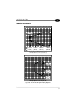
Страница 123: ...320 0 13 mm 5 mils 0 30 mm 12 mils 0 50 mm 20 mils 0 20 mm 8 mils 0 20 mm Reading Diagram TC1100 0100 code 39 90 80 70 60 50 40 30 20 10 0 10 20 30 40 50 60 70 80 90 0 10 20 30 40 50 60 70 80 90 100 110 120 130 140 150 160 170 180 0 17 mm 6 6 mils 0 38 mm 15 mils 0 25 mm 10 mils Reading Diagram TC1100 0200 PDF417 Figure 35 TC1100 Scan Engine Reading Diagrams ...

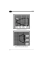
Страница 124: ...ls 0 30 mm 12 mils 0 50 mm 20 mils 0 20 mm 8 mils 0 20 mm mm Reading Diagram TC1100 1100 code 39 90 80 70 60 50 40 30 20 10 0 10 20 30 40 50 60 70 80 90 0 10 20 30 40 50 60 70 80 90 100 110 120 130 140 150 160 170 180 0 17 mm 6 6 mils 0 38 mm 15 mils 0 25 mm 10 mils mm Reading Diagram TC1100 1200 PDF417 Figure 36 TC1100 Scanner Reading Diagrams ...

Страница 125: ...al 5 bars i12k i12k i12k i01k i01k i01k 2 5 matrix 3 bars EAN 8 i23k i23k i23k i k i k i k EAN 13 UPC A i k i k i k i k i k i k UPC E EAN 8 with 2 ADD ON i k i k i k i k i k i k EAN 8 with 5 ADD ON EAN 13 with 2 ADD ON i k i k i k i k i k i k EAN 13 with 5 ADD ON UPC A with 2 ADD ON i k i k i k i k i k i k ...

Страница 126: ... k i k i k i k i k i k Code 39 Code 39 Full ASCII i78k i78k i78k i89k i89k i89k CODABAR ABC CODABAR i34k i34k i34k i45k i45k i45k Code 128 EAN 128 i56k i56k i56k iLMk iLMk iLMk Code 93 CIP 39 i67k i67k i67k i k i k i k CIP HR Code 32 iFGk iFGk iFGk i9 k i9 k i9 k ISBT 128 iGHk iGHk iGHk ...

Страница 127: ...ndard CODABLOCK F EAN iMNk iMNk iMNk iNOk iNOk iNOk MSI Plessey Anker i k i k i k iPQk iPQk iPQk Plessey Standard Delta IBM iBCk iBCk iBCk iDEk iDEk iDEk Telepen Code 16K iEFk iEFk iEFk iQRk iQRk iQRk PDF417 Code 49 iSTk iSTk iSTk iRSk iRSk iRSk Pharmacode iTUk iTUk iTUk ...

Страница 128: ...TC1100 120 A ...
Страница 129: ... States relating to electromagnetic compatibility and product safety Basées sur la législation des Etates membres relative à la compatibilité électromagnétique et à la sécurité des produits Über die Annäherung der Gesetze der Mitgliedsstaaten in bezug auf elektromagnetische Verträglichkeit und Produktsicherheit entsprechen Basado en la aproximación de las leyes de los Países Miembros respecto a la...

Страница 130: ... 3E i 69 NAK 15 3F j 6A SYN 16 40 k 6B ETB 17 A 41 l 6C CAN 18 B 42 m 6D EM 19 C 43 n 6E SUB 1A D 44 o 6F ESC 1B E 45 p 70 FS 1C F 46 q 71 GS 1D G 47 r 72 RS 1E H 48 s 73 US 1F I 49 t 74 SPACE 20 J 4A u 75 21 K 4B v 76 22 L 4C w 77 23 M 4D x 78 24 N 4E y 79 25 O 4F z 7A 26 P 50 7B 27 Q 51 7C 28 R 52 7D 29 S 53 7E T 54 DEL 7F i k i k i k 0 i k i k i k i k i k i k 1 2 i k i k i k i k i k i k 3 4 i k...
Страница 131: ... States relating to electromagnetic compatibility and product safety Basées sur la législation des Etates membres relative à la compatibilité électromagnétique et à la sécurité des produits Über die Annäherung der Gesetze der Mitgliedsstaaten in bezug auf elektromagnetische Verträglichkeit und Produktsicherheit entsprechen Basado en la aproximación de las leyes de los Países Miembros respecto a la...

Отзывы: