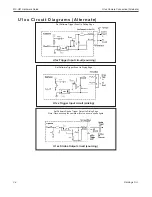
U1xx Camera Connection (Alternate)
MX-U81 Hardware Guide
Datalogic S.r.l.
3-8
U1xx Camera Connection (Alternate)
IMPORTANT
: This section describes how to connect MX-U81 cameras using the older, discrete
style of terminal block. To use the newer, integrated style of terminal block, see “Connecting the
Camera” on page 3-5.
WARNING
: Never wire U1xx Camera Strobe Outputs in parallel with other U1xx Camera
Strobe Outputs. This will damage the cameras.
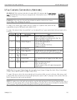
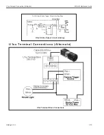
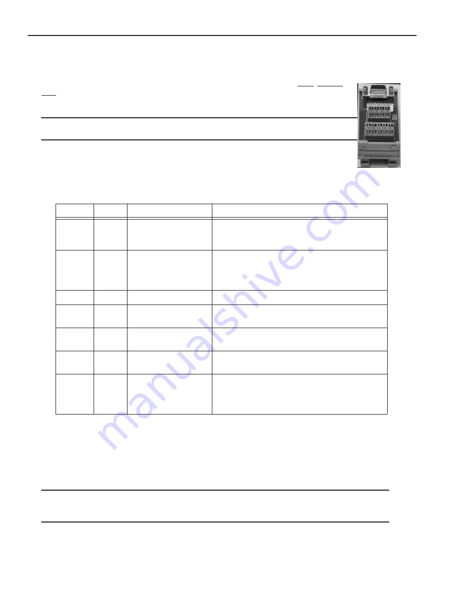
To connect U1xx camera trigger signals and strobe outputs, use a terminal block (248-0140) and
optional Hirose 6-pin to DB9 camera cable (606-0674-xx).
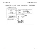
To connect the camera without a terminal block, use the optional Hirose 6-pin to unterminated cable (part number 606-
0672-xx).
NOTE
: The U1xx camera's Strobe Trigger Out is normally closed (it opens to trigger the strobe). Do not wire multiple
cameras' strobe outputs in parallel to trigger a single strobe.
To connect the power cable to the camera, align the cable connector with the connector on the rear of the camera, push
gently until the cable connector seats securely, then tighten the connector collar. To disconnect it, loosen the collar com-
pletely, then grasp the connector and gently pull.
NOTE
: To reduce stress on the cable and connectors, loop the cable and fasten it to the camera's mounting block. Do not
crimp or tie the cable tightly with wire ties as this may damage it internally. The cable is not intended for continuous flex-
ing or movement. The cable's maximum bend radius is fifteen times the cable diameter.
Terminal
Color
Signal Name
Notes
1
Blue
DO NOT USE
Do NOT apply power to this terminal.
Power is supplied by the USB connector. See “Top
Panel Connections” on page 1-6.
2
Orange
Camera Trigger In
0 to +24 VDC recommended
Off: 0 to +1.4 VDC
On: +2.2 to +24 VDC; 5 to 15 ma
M30 VDC
3
Green
No Connection
4*
Wht/
Grn
Strobe Trigger Out
DO NOT APPLY ANY VOLTAGE DIRECTLY TO THIS
OUTPUT. DO NOT WIRE OUTPUTS IN PARALLEL.
5
Wht/
Org
I/O Ground
6
Wht/
Blu
DO NOT USE
Not required. Ground is supplied by the USB connec-
tion.
7*
None
Strobe VCC
Based on Strobe requirement
Max: +30 VDC; 50 ma
(*Block contains 1k Ohm 2W resistor between termi-
nals 4 and 7)
Содержание MX-U81
Страница 1: ...MX U81 Hardware Guide for Processor and Cameras Revision Date October 26 2017 ...
Страница 4: ......
Страница 26: ...Battery MX U81 Hardware Guide Datalogic S r l 2 10 ...
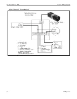
Страница 33: ...MX U81 Hardware Guide U1xx Camera Connection 3 7 Datalogic S r l U1xx Terminal Connections ...
Страница 52: ...JAI Camera MX U81 Hardware Guide Datalogic S r l 3 26 ...
Страница 64: ...U1xx MX U81 Hardware Guide Datalogic S r l 5 4 ...


