STEP 5 - DEVICE CONFIGURATION
PRODUCT REFERENCE GUIDE 27
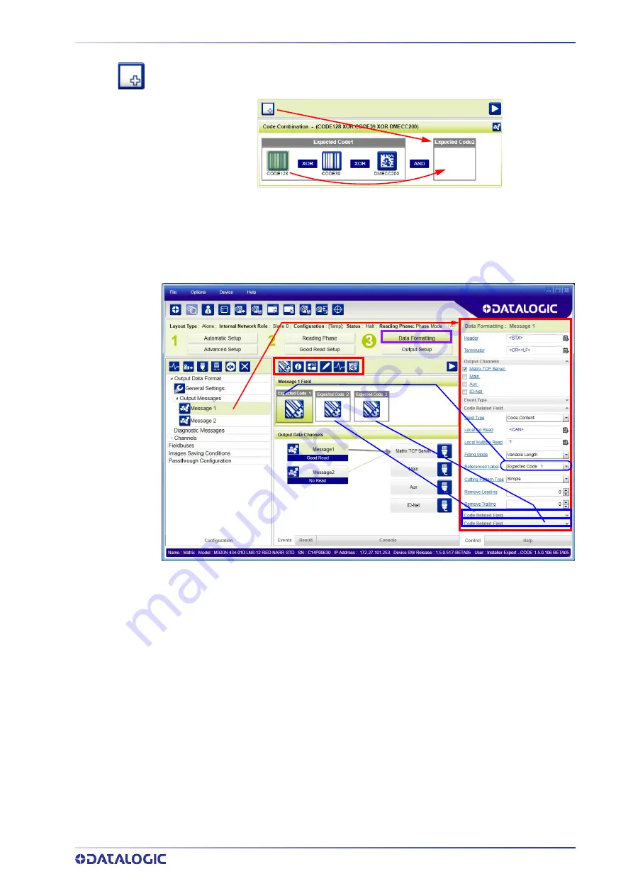
To create a logical AND condition from a logical XOR, create a new Expected Code box
using the Add icon. Then drag the desired code icon from one box to the other.
Data Formatting
1. Configure your application specific Data Formatting Message(s) from the Configu-
ration Parameters tree area: Message 1, Message 2, etc.
You can add fields to the output message by clicking on the icons above the Message
Field area. They will be appended to the message. You can drag them to position them
between other fields in the message so that the output message is ordered according to
your application requirements.
Each field has its own relative configuration parameters in the parameters panel.
Содержание Matrix 120
Страница 1: ...Matrix 120 PRODUCT REFERENCE GUIDE Image Based Reader...
Страница 14: ...GENERAL VIEW XIV MATRIX 120...
Страница 63: ...mm in MECHANICAL DIMENSIONS PRODUCT REFERENCE GUIDE 49 Figure 29 Mounting Bracket Overall Dimensions...
Страница 75: ...INPUTS PRODUCT REFERENCE GUIDE 61 Figure 41 NPN External Trigger Using Matrix 120 Power...
Страница 95: ...GLOBAL FOV DIAGRAMS PRODUCT REFERENCE GUIDE 81 2D Codes Figure 64 Global FOV 2D Code Diagram for MP Models...
Страница 97: ...GLOBAL FOV DIAGRAMS PRODUCT REFERENCE GUIDE 83 Matrix 120 310 xxA Models Digimarc Barcode...
Страница 149: ...IMAGE CROPPING PRODUCT REFERENCE GUIDE 135 The cropped area can be moved by dragging the center...
Страница 153: ...Reader 2 Reader 3 PASS THROUGH CONFIGURATIONS PRODUCT REFERENCE GUIDE 139...
Страница 177: ...OUTPUTS PRODUCT REFERENCE GUIDE 163 Figure 4 NPN Output Connection Figure 5 Push Pull Output Connection...
Страница 185: ......
Страница 186: ......
Страница 187: ......


