background image

E-GENIUS 


97 


4.4  MODIFY SETTINGS | SYSTEM INFO 

Use 

System Info

 to identify and name the scanning system (whether it includes one AV7000 barcode 

reader  or  an  array),  indicate  Master  or  Standalone  systems,  discover  the  cameras  included  in  the 
system, and distribute software from the Master AV7000 to Slave AV7000s in the system. 

To view system information:


1.  In  the  menu  tree  under 

Modify  Settings

,  click 

System  Info

.  The 

System  Info

 window 

opens. 


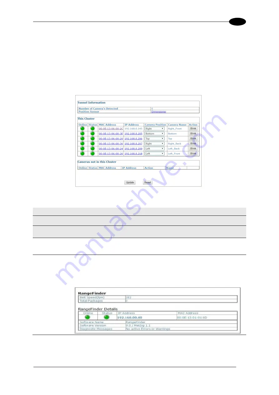
2.  The information in this form is auto-filled.  The fields are described below: 
 

Field Name 

Action/Definition 

System Info 

Tunnel Information 

Number of 
Cameras 
Detected 

Displays the number of cameras found in the system. 

Position Sensor 
Detected 

Displays  the  type  of  Position  sensor.    Indicates  whether  it  is  a  RangeFiner  or  a 
Dimensioner  that  is  Detected.    Rangefinder  or  Dimensioner  will  display  and  be 
hyperlinked to the corresponding device setup software. 
 
For example:  Click Rangefinder and the following displays: 


Содержание AV7000

Страница 1: ...REFERENCE MANUAL AV7000 Linear Camera...

Страница 2: ...to a retrieval system or transmitted in any form or by any means or for any purpose without the express written permission of Datalogic S p A and or its affiliates Datalogic and the Datalogic logo are...

Страница 3: ...nction Buttons HMI Human Machine Interface 7 1 9 Accesories 8 1 10 Photoelectric Sensor 11 1 11 Area Sensor 12 1 12 Encoder Tachometer 13 1 13 PGD100 Non Contact Speed Detector 14 1 14 CBX Industrial...

Страница 4: ...ons 60 3 8 1 Power Supplies and Supply Capacity When Wiring to AI7000s 60 3 9 Wiring Into the CBX Connection Box 62 3 9 1 Selecting the Correct CBX Connection Box for Your Application 63 3 10 CBX100 C...

Страница 5: ...4 7 Diagnostics 184 4 7 1 Diagnostics System Status 185 4 7 2 Diagnostics System Health 188 4 7 3 Diagnostics Input Output Status 189 4 7 4 Diagnostics Serial Comm Status 189 4 7 5 Diagnostics Device...

Страница 6: ...ng Linear Barcodes 282 5 11 2 Reading 2D Barcodes 286 6 MAINTENANCE 290 6 1 Overview 290 6 2 Recommended Maintenance Frequency 291 6 3 Maintenance Tasks 291 6 3 1 Cleaning the Illumination and Camera...

Страница 7: ...g Data Sheets Manuals Software Utilities and Drawings Repair Program for On Line Return Material Authorizations RMAs plus Repair Center contact information Service Program containing details about Mai...

Страница 8: ...NOTE This symbol draws attention to details or procedures that may be useful in improving maintaining or enhancing the performance of the hardware or software being discussed COMPLIANCE ELECTRICAL SA...

Страница 9: ...installing the device or during maintenance to avoid unintentional exposure to LED light Avoid staring at the LEDs as one would with any very strong light source such as the sun WARNING There are no u...

Страница 10: ...duct In a domestic environment this product may cause radio interference in which case the user may be required to take adequate measures EAC COMPLIANCE Customs Union The CU Conformity certification h...

Страница 11: ...xi GENERAL VIEW Figure 2 AV7000 Camera Front View Figure 3 AV7000 Camera Back View...

Страница 12: ...der Focusing Calibration see section 5 2 2 DS2 Light Array Calibration see section 5 2 3 AS1 Area Sensor Alignment see section 5 7 Camera Calibration Static see section 5 3 2 Camera Calibration Dynami...

Страница 13: ...barcode reader camera for acquiring the images locating and reading the codes on the target 2 A lighting system for illuminating the target codes to be acquired 0 Practical reading system applications...

Страница 14: ...than one barcode reader illuminator pair is necessary multi camera reading station In this case one of the barcode readers the Master collects the information from all the sensors and distributes it t...

Страница 15: ...parcel measured by a height sensor The Datalogic sensors may be a RangeFinder DM3610 Dimensioner or AREAscan DS2 Light Array LCC 75xx Light Curtain Kit Trigger Source The camera needs to know when to...

Страница 16: ...on only during its camera s acquisition time All the cameras are then synchronized so cameras with crossing illuminator lobes never acquire simultaneously When a camera is not supposed to acquire its...

Страница 17: ...ding low aspect ratio barcodes Reading of codes covered by plastic film Reading of codes with a large depth of field Reading codes within a wide field of view Reading of high resolution codes position...

Страница 18: ...0 BARCODE READER AV7000 1000 140mm f 5 6 STD 934001000 AV7000 1100 140mm f 5 6 SHORT RANGE 934001010 AV7000 1200 110mm f 8 0 934001020 AV7000 1300 90mm f 8 934001030 AI7000 ILLUMINATION AI7000 800 SHO...

Страница 19: ...wo external buttons that can be used to perform specific tasks without the need of connecting to e Genius AV7000 browser based user interface See section 5 9 for functional description Figure 10 AV700...

Страница 20: ...ER DLA 0 2IN 5MM 10MM 93ACC0157 RANGEFINDER DLA 0 5IN 20MM 93ACC0159 CAB GE01 M12 IP67 TO RJ45 1M 93A050034 CAB GE03 M12 IP67 TO RJ45 3M 93A050035 CAB GE05 M12 IP67 TO RJ45 5M 93A050036 CAB GE10 M12 I...

Страница 21: ...002738 ETHERNET SWITCHES SINGLE GIG 8 PORT SWITCH ENCLOSURE 93ACC0160 DUAL GIG 8 PORT SWITCH ENCLOSURE 93ACC0131 SYNC CABLES CAB GE03 M12M TO M12F 3M 93A050079 CAB GE05 M12M TO M12F 5M 93A050080 CAB G...

Страница 22: ...CONN SERVICE 93ACC1877 BA400 M12 3P M PANEL CONN EXT POWER 93ACC1853 BA500 M12 4P F PANEL CONN TRIGGER 93ACC1854 BA600 M12 5P F PANEL CONN ID NET OUT 93ACC1855 BA700 M12 5P M PANEL CONN ID NET IN 93A...

Страница 23: ...he photoelectric sensor assists in maintaining the package footprint so that the AV7000 camera will only scan and provide data for a specific package Depending on the application these devices may nee...

Страница 24: ...ontrolled height and width Versions with trimmer adjustment and optic synchronism between emitter and receiver unit are available Area sensors also help avoid multiple triggers on irregular shaped pac...

Страница 25: ...an be used to help track the package position along the length of the conveyor See section 3 10 3 and 3 11 3 for wiring options Figure 13 Encoder Tachometer Mounting Bracket and Cable Encoder Tachomet...

Страница 26: ...tact encoder tachometer will not work as in a Cross Belt Sorters or Tilt Tray system where a continuous belt surface is not available The speed detector is designed to function as an encoder tachomete...

Страница 27: ...o an encoder tachometer photoelectric sensor serial devices relays or other peripherals See section 3 10 for wiring options Figure 15 CBX500 CBX800 and CBX100 Connection Boxes shown CBX Connection Box...

Страница 28: ...rating distances for high resolution versions or 10m for low resolution versions Digital resolution is 12mm or 35mm while relative measurement precision is 6mm or 22 5mm See section 5 2 3 for informat...

Страница 29: ...angeFinders can also be used to provide rough dimensioning data See section 5 2 2 for information on installing and calibrating the RangeFinder Figure 17 RangeFinder The RangeFinder module includes th...

Страница 30: ...certified Legal for Trade side by side package detection or volume measurements for the packages that pass below it See section 0 for information on setting up the DM3610 For complete information abo...

Страница 31: ...s on connecting your readers to other devices in the system WARNING Electrical Installation must be performed by Qualified Service Technicians Only Procedures may involve exposure to high voltage A tr...

Страница 32: ...irror and brackets 2 2 UNPACKING INSTRUCTIONS Verify that the AV7000 Camera and all the parts supplied with the equipment are present and intact when opening the packaging the list of parts includes F...

Страница 33: ...ANICAL INSTALLATION 21 2 Figure 20 AI7000 Illumination package contents Important Be sure to retain shipping boxes and packing material for use if the unit needs to be returned to Datalogic for any re...

Страница 34: ...to its mounting brackets 6 Mount the fan assembly to the AV7000 Camera 7 Mount the AV7000 Camera to the Illuminator 8 Mount the brackets for the deflection mirror if required 9 Mount the deflection m...

Страница 35: ...TANT The AV7000 is a sealed unventilated unit Mounting the unit with 300 mm 12 in of clearance front top and sides is recommended for cooling and ease of maintenance Note The AV7000 datum is indicated...

Страница 36: ...roximately 300 mm 12 in for wiring The first camera in the system must be installed at least 254 mm 10 in upstream from the focus device DM3610 RangeFinder or light curtain to work properly Route wire...

Страница 37: ...or proper servicing 2 4 6 Scanning Station Frame Mounting Structure Preparation and Positioning The vision system components and in particular the mounting brackets have been designed for installation...

Страница 38: ...stance between the profiles measured from the internal sides is given in the following table depending on the illuminator model Illuminator Body Width x Distance Between Rail Slots with Rising Bracket...

Страница 39: ...amera contains 2 ST 0325 universal main brackets 2 ST 0326 universal support brackets 2 ST 0344 universal rising brackets 4 M8x8 bolts for support to main bracket assembly 8 M8x12 bolts for illuminato...

Страница 40: ...Bracket Assembly and Mounting Both Top and Bottom Camera positions require the same pre assembly of the Illuminator Bracket Figure 26 Bracket Assembly for Top and Bottom Mounted Cameras Exploded View...

Страница 41: ...ount the cooling fan to the AV7000 camera See section 2 4 11 2 Pre assemble the Illuminator brackets according to the application 3 Mount the brackets to the mounting frame Use two 2 T bolts per brack...

Страница 42: ...ed to the brackets Typically the brackets are pre assembled and attached to the mounting structure and then the illumination is mounted to its brackets The Support Bracket green in the figure passes t...

Страница 43: ...d the Rising Bracket red surface for mounting purposes the top bracket should be pre assembled so that this distance is 0 mm in This will provide clearance when placing the camera illuminator between...

Страница 44: ...t the bracket to the station frame 4 Place the lower end of the illumination on the bottom bracket and then tilt the top end of the illumination in line with the top bracket 5 Lower the top support br...

Страница 45: ...and Rising Bracket red NOTE In most applications the viewing angle is created with a deflection mirror and its brackets and the camera is mounted at 90 degrees NOTE The left and right references show...

Страница 46: ...AV7000 LINEAR CAMERA REFERENCE MANUAL 34 2 Figure 33 Standard SIDE Mount AV7000 Bracket Angles with locking bolt position...

Страница 47: ...s In some cases when you need to save space the AV7000 Camera and deflection mirror can be mounted directly between the rails without the use of the Rising Bracket Figure 34 Alternative Mounting TOP C...

Страница 48: ...hout the cooling fan attached to the top of the housing Before mounting the camera to the illuminator first mount the fan to the camera housing as shown below To mount the cooling fan to the camera ho...

Страница 49: ...follows 1 Make sure the illuminator is firmly mounted to the mounting structure 2 Remove the dust cap from the lens access on the back of the illuminator Figure 37 Illuminator Dust Cap 3 Lift the came...

Страница 50: ...tor Finger tighten the bolt for now to secure the camera and prevent it from slipping out of the illumination NOTE The spring loaded Focus Lock will push against the illuminator creating some resistan...

Страница 51: ...d for precise image capture Figure 40 Deflection Mirror Examples Deflection mirrors are mounted much like the illuminations and use the same Rising Bracket with a modified Main Bracket The illustratio...

Страница 52: ...ting bolts Once mounted loosen the main bracket bolts and angle the mirror as desired Figure 41 Top mirror mounting position Important It is critical that the brackets do not stress or flex the mirror...

Страница 53: ...MECHANICAL INSTALLATION 41 2 45 View Angle Top or Outside Side Figure 42 45 View Angle Top or Side...

Страница 54: ...AV7000 LINEAR CAMERA REFERENCE MANUAL 42 2 15 View Angle Top or Outside Side Figure 43 15 View Angle Top or Side...

Страница 55: ...V7000 Cameras and deflection mirrors on the inside of the mounting structure closer to the conveyor as shown below Notice that to achieve a 15 degree locking angle the mirror must be mounted on the ou...

Страница 56: ...AV7000 LINEAR CAMERA REFERENCE MANUAL 44 2 15 View Angle Inside Side Figure 45 15 View Angle Inside Side...

Страница 57: ...MECHANICAL INSTALLATION 45 2 15 View Angle with Old Bracket Inside Side Figure 46 15 View Angle with Old Bracket Inside Side...

Страница 58: ...mirror 41 degrees off the horizontal as shown below Securely tighten the bracket bolts 8 View Angle Bottom Read Figure 47 Bottom Mounted Deflection Mirror NOTE A bottom read mirror should be mounted u...

Страница 59: ...ances A and B shown in the illustration below Distances A and B are measured to the edge of the Rising Bracket base as shown When mounting the readers and mirrors make sure the structure is centered a...

Страница 60: ...anical installation details Most AV7000 applications are shipped with the CBX connection box and all the necessary cabling required to electrically install the system If your system requires custom le...

Страница 61: ...PE ground 5 If used wire the photoelectric sensor or other trigger to the CBX connection box 6 Wire the tachometer to the CBX connection box 7 Wire serial ports to the CBX connection box if needed 8...

Страница 62: ...y take the place of the encoder when a tilt tray or cross belt conveyance is used NOTE A CBX510 Connection Box can be used in place of the CBX100 Connection Boxes shown in the following block diagrams...

Страница 63: ...ELECTRICAL INSTALLATION 51 3 3 3 2 Single Head AV7000 with RangeFinder Figure 52 Single AV7000 with RangeFinder See section 3 8 1 for AV7000 power supply connections...

Страница 64: ...NUAL 52 3 3 3 3 Single Head AV7000 with LCC 75xx Light Curtain Kit Figure 53 Single AV7000 with LCC 75xx Light Curtain Kit See section 5 2 3 for LCC 75xx power supply connections See section 3 8 1 for...

Страница 65: ...ELECTRICAL INSTALLATION 53 3 3 3 4 Master Slave Array with DM3610 Figure 54 Master Slave Array Tunnel with DM3610 See section 3 8 1 for AV7000 power supply connections...

Страница 66: ...AV7000 LINEAR CAMERA REFERENCE MANUAL 54 3 3 3 5 Master Slave Array with RangeFinder Figure 55 Master Slave Array Tunnel with RangeFinder See section 3 8 1 for AV7000 power supply connections...

Страница 67: ...e Array with LCC 75xx Light Curtain Kit Figure 56 Master Slave Array Tunnel with LCC 75xx Light Curtain Kit See section 5 2 3 for LCC 75xx power supply connections See section 3 8 1 for AV7000 power s...

Страница 68: ...tion perpendicular Avoid running power and data wiring parallel to each other If possible maintain one of the following separations between the power and data wiring 300 mm 12 in gap use steel conduit...

Страница 69: ...nnector on AV7000 15 FANS Supplies DC power to AI7000 illumination fan units AV7000 Camera 16 FAN Supplies DC power to AV7000 fan unit 17 I O Provides connection to CBX Connection Box 18 FOCUS SER Pro...

Страница 70: ...hould always be covered with its protective cap Figure 58 Connector protective caps Route wiring from the barcode reader s connector panel through the wiring channels if available on the Datalogic mou...

Страница 71: ...s available for the AI7000 Illumination which then supplies the AV7000 Camera However if your installation requires custom power supply wiring the pin outs of the AV7000 camera power connector are pro...

Страница 72: ...for wiring recommendations for safety ground The CBX connection boxes provide flexible connectivity to a range of I O devices as well as serial hosting The AV7000 connects to the CBX via its I O port...

Страница 73: ...e Figure 61 Connecting PWR 480B to AI7000 Illuminator NOTE The AI7000 series illuminators are supplied with a CVL 2389 extension power cable Use this cable to connect the PWR 480B power supply by cutt...

Страница 74: ...n the base of the CBX connection box CBX100 shown Insert the cables allowing enough slack for the individual wires to reach the appropriate pin block connectors Securely tighten the water tight seals...

Страница 75: ...n or power sourcing CBX800 used for Fieldbus communication between standalone or master cameras and a Host Various Fieldbus modules can be installed in the CBX800 The master camera communicates throug...

Страница 76: ...M switch to OFF 2 Set POWER SUPPLY jumper to FROM DEVICE 3 Insert jumper wire in pin block from REF to ID one jumper in either block is sufficient NOTE In order for a standalone or Master AV7000 to in...

Страница 77: ...nnection box is configured for the AV7000 application as follows Figure 64 CBX500 Initial Setup 1 Set ID NET TERM switch to OFF 2 Set RS422HD TERM switch to OFF 3 Set Shield jumper to FILTERED Earth 4...

Страница 78: ...T RS485HD TERM switch to OFF 2 Set Power Source Selector jumper to FROM SOURCE 3 Set Shield jumper to FILTERED Earth 4 Insert jumper wire in pin block from REF to ID one jumper in either block is suff...

Страница 79: ...ollow the appropriate wiring diagram to assure proper wiring IMPORTANT You must use shielded interface cables with this product NOTE To confirm the photoelectric sensor is functioning properly watch t...

Страница 80: ...AV7000 LINEAR CAMERA REFERENCE MANUAL 68 3 Photoelectric Sensor PNP Output Figure 67 Photoelectric Sensor Wiring PNP Output...

Страница 81: ...10 2 AS1 Area Sensor Connections to CBX100 CBX500 CBX800 The AS1 area sensors can detect and provide trigger for very small or irregularly shaped objects AS1 Area Sensor PNP Output Figure 68 AS1 Area...

Страница 82: ...meter and mounting kit Use the cable provided with the tachometer to connect to the CBX100 CBX500 pin block as shown below Encoder Tachometer Wiring for NPN Output Figure 69 OEK 2 Encoder Tachometer W...

Страница 83: ...oder Tachometer Wiring PNP Output Figure 70 OEK 2 Encoder Tachometer Wiring PNP Output NOTE Some Photocraft tachometers may have a different color coding V Red or White Orange Signal White or White Bl...

Страница 84: ...AV7000 FOCUS SER When using a DM3610 dimensioner for focusing the DM3610 s CBX box must be wired to the focus serial FOCUS SER port of the master AV7000 using a flying lead to M12 cable FOCUS CONTROL...

Страница 85: ...llustrate the different types of serial communications available via the CBX100 pin block It is very important that you make the proper pin connections RS232 with No Handshaking Use RS232 for a direct...

Страница 86: ...tion to a controller personal computer or other device RS422 provides point to point communications at distances up to 1200 M 3940 ft Full duplex wiring supports a four wire double twisted pair RxD Tx...

Страница 87: ...including Life Light Trigger Output Error Light Ready Light Good Dim and No Dim Schematics for Isolated and Non Isolated relays are provided below Outputs 1 and 2 Maximum Voltage 30 V Figure 74 OUTPUT...

Страница 88: ...AV7000 LINEAR CAMERA REFERENCE MANUAL 76 3 Powered Outputs Figure 76 Powered Output Connections...

Страница 89: ...a trigger device The photoelectric sensor is wired directly into the CBX510 terminal block If your application uses a trigger other than the one specified by Datalogic follow the appropriate wiring d...

Страница 90: ...AV7000 LINEAR CAMERA REFERENCE MANUAL 78 3 Photoelectric Sensor to CBX510 NPN Figure 78 Photoelectric Sensor Wiring NPN Output...

Страница 91: ...ELECTRICAL INSTALLATION 79 3 Photoelectric Sensor to CBX510 PNP Figure 79 Photoelectric Sensor Wiring PNP Output...

Страница 92: ...CE MANUAL 80 3 3 11 2 AS1 Area Sensor to CBX510 Connections The AS1 area sensors can detect and provide trigger for very small or irregularly shaped objects AS1 Area Sensor PNP Output Figure 80 AS1 Ar...

Страница 93: ...g to CBX510 Encoder Tachometer Wiring for NPN Output to CBX510 Figure 81 OEK 2 Encoder Tachometer Wiring NPN Output NOTE Some Photocraft tachometers may have a different color coding V Red or White Or...

Страница 94: ...Tachometer Wiring for PNP Output to CBX510 Figure 82 OEK 2 93ACC1770 Encoder Tachometer Wiring PNP Output NOTE Some Photocraft tachometers may have a different color coding Red V or White Orange White...

Страница 95: ...FOCUS SER When using a DM3610 dimensioner for focusing the DM3610 s CBX box must be wired to the focus serial FOCUS SER port of the master AV7000 using a flying lead to M12 cable FOCUS CONTROL 5MT CAB...

Страница 96: ...ories Schematics for Isolated and Non Isolated digital outputs are provided below Outputs 1 3 Figure 84 OUTPUTS Block Maximum Voltage 30 Vdc Collector Current pulse 130 mA Max Collector Current contin...

Страница 97: ...ELECTRICAL INSTALLATION 85 3 3 11 7 Powered Outputs Figure 86 Powered Outputs NPN PNP...

Страница 98: ...eters and photoelectric sensors are mounted is grounded to the conveyor or to the PE terminal inside the PWR 3 The Shield wires from the Encoder Tachometer and photoelectric sensor cables are connecte...

Страница 99: ...se can be used to change parameters without the need of an external computer Figure 88 VGA USB Interface Panel Kit external connectors and internal cables To install the optional VGA USB Interface Pan...

Страница 100: ...ide camera 4 Connect the VGA cable on the back of the VGA USB Interface Panel Kit to the VGA connector inside the back of the camera Figure 91 Connecting VGA Cable 5 Connect the USB cable on the back...

Страница 101: ...e camera is powered on the monitor will come on after several seconds and display an image of the AV7000 camera system To access a browser Firefox right click with the mouse on the monitor window A dr...

Страница 102: ...diagnostics for the system The e Genius enables you to configure fine tune and monitor your scanning system operations IMPORTANT Please clear the PC s browser cache regularly or set up the browser to...

Страница 103: ...er click View network connections c Right click Local Area Connection and then select Properties d Select the Networking tab Under This connection uses the following items click Internet Protocol Vers...

Страница 104: ...valid the application enables all functions available to the user and displays the System Info window If the password is not valid the application displays a results box with the message Incorrect Pas...

Страница 105: ...y additional setup features 4 2 2 Entering Text Using the Text Entry Tool In cases where text needs to be entered to create message headers trailer custom messages or for other reasons the Text Entry...

Страница 106: ...Welcome page provides important product information as well as three ways to find specific help information Contents Index and Search To display contextual help for a current window 1 Click the Help...

Страница 107: ...E GENIUS 95 4 Click Show to access Contents Index and Search options...

Страница 108: ...AL 96 4 4 3 MODIFY SETTINGS Use the Modify Settings Menu Tree selections during initial setup to configure your scanning system If necessary you can later make modifications to the configuration using...

Страница 109: ...r Modify Settings click System Info The System Info window opens 2 The information in this form is auto filled The fields are described below Field Name Action Definition System Info Tunnel Informatio...

Страница 110: ...to view details about that specific device See Device Details below IP Address Displays the internal IP address of the unit used for camera to camera communication Camera Position Select Not Assigned...

Страница 111: ...4 4 4 1 Device Details From the System Info window click on a device s MAC Address to open a window displaying details about that device The details include statistics decoder software and processor...

Страница 112: ...tree selections during initial setup to configure your camera system Global settings are applied to the system Master and then distributed by the Master AV7000 to the Slave devices If necessary you ca...

Страница 113: ...ating Mode to set up the physical parameters for your system including encoder trigger conveyor and position sensor attributes To edit the system Operating Mode 1 In the menu tree under Modify Setting...

Страница 114: ...m 12 in 192 1 5875 16 1000019875 304 8 mm 12 in 240 1 27 20 1000019875 300 mm 11 81 in 192 1 5625 16 OEK 2 93ACC1770 300 mm 11 81 in 240 1 25 20 OEK 2 93ACC1770 304 8 mm 12 in 2400 0 127 200 OEK 3 93A...

Страница 115: ...on In an application with opposing side read cameras it is the distance from the left side camera s Far Working Distance point to the right side camera s Far Working Distance point measuring across th...

Страница 116: ...to Sensor Enter a distance to extend the trailing edge of the photo sensor by Crossbelt Sorter Mode Select Enabled or Disabled from the drop down list if your system requires crossbelt sorter mode Pos...

Страница 117: ...the data for the sides Essentially the range used in the bounding is about 25 mm 1 in less than twice this number in other words if left at 70 mm 3 in bounding is performed over approximately 127 mm...

Страница 118: ...ages in your system To edit the system Object Detection 1 In the menu tree under Modify Settings navigate to Global Settings Object Detection The Object Detection window opens NOTE Default values are...

Страница 119: ...pe To edit the Barcode Settings Table Settings 1 In the menu tree under Modify Settings navigate to Global Settings Barcode Settings Barcode Settings Table The Barcode Settings Table window opens 2 En...

Страница 120: ...ilable in the Code Symbology drop down list Add On EAN and UPC Codes only Select No Add On 2 digits Add On or 5 digit Add On from the Add On drop down list Selecting 2 digit Add On or 5 digit Add On a...

Страница 121: ...ches any single digit w Matches any word character alphanumeric underscore XYZ Matches any single character from the character class XYZ Matches one or more of any of the characters in the set Matches...

Страница 122: ...Check Digit Full ASCII Select the check box to enable full ASCII This pertains to Code 39 only Quiet Zone Specify the quiet zone in the field provided This defines the minimum quiet zone white margin...

Страница 123: ...the Data Matrix square codes Select All Rectangle to select all of the Data Matrix rectangular codes Select Clear to clear the table of any selections Postal Symbologies Select a symbology from the d...

Страница 124: ...ight Enter the minimum height of codes the system is expected to read This parameter defines the minimum height of the barcode the AV7000 will read The minimum height is 6 mm 25 in Code Combination Se...

Страница 125: ...al No Read will be produced NOTE In case of Multi Label the codes will be distinguished EITHER by their symbology OR by their contents If two or more codes share the same symbology and content the bar...

Страница 126: ...e read or decoded Disable No Read Message The No Read Message is not transmitted Global No Read Message The No Read String will be sent if the barcode reader is unable to decode one or more barcodes i...

Страница 127: ...from the code and therefore reduce the code length collapsed It can even be null Replacement Char Click to activate the Text Entry Tool and enter the substitution character to replace all the strippe...

Страница 128: ...e No Read Message drop down list Click Submit to save your text to the origin window text field or click Cancel to return to origin window without transferring text Multiple Read Message Select Disabl...

Страница 129: ...se Select the check box to remove the stripped characters from the code and therefore reduce the code length collapsed It can even be null Replacement Char Click to activate the Text Entry Tool and en...

Страница 130: ...tion window reveals related input fields NOTE The Logical Combination option is only available when more than one code is enabled in the Barcode Settings Table 1 Enter the appropriate information in t...

Страница 131: ...follows 1 Define the Barcode Settings indicating the type of expected code labels It is possible to define up to 10 different code types 2 Define how many code types groups are expected by editing the...

Страница 132: ...ubmit to save your text to the origin window text field or click Cancel to return to origin window without transferring text This parameter is only available when Multiple Read Message is enabled and...

Страница 133: ...bal No Read Message Terminator X Header Global No Read Message Terminator X X Header Code 128 data Data Packet Separator Code 128 data Terminator NOTE If Multiple Read Message is enabled and a third l...

Страница 134: ...Combination Rule 1 2 Defines a single group expecting a Code 39 label OR a Code 128 label Decoded Code Symbology Output Message Label 1 Label 2 Header Global No Read Message Terminator X Header Code 3...

Страница 135: ...bel 1 Second Label 1 Third Label 1 Label 2 Header Global No Read Message Terminator X Header Global No Read Message Terminator X Header Global No Read Message Terminator X Header Global No Read Messag...

Страница 136: ...er Global No Read Message Terminator X Header Global No Read Message Terminator X Header Global No Read Message Terminator X X Header Global No Read Message Terminator X X X Header Code93 DPS First de...

Страница 137: ...ot transmitted Global No Read Message The No Read String will be sent if the barcode reader is unable to decode one or more barcodes in the reading phase Local No Read s Message This allows the user t...

Страница 138: ...the code Click Submit to save your text to the origin window text field or click Cancel to return to origin window without transferring text Strip Filter Collapse Select the check box to remove the s...

Страница 139: ...te White on Black or Both from the drop down list to match the kind of barcodes read by the system Advanced Localizer Settings Enable Advanced Localizer Select the check box to enable the advanced loc...

Страница 140: ...Ethernet communication The Transports parameters are used to setup the serial or Ethernet configuration to match the transmit receive parameters of the external interface To edit the Transports setti...

Страница 141: ...dex Select and index number from the drop down list This selection is available when Data Output Protocol Advanced is selected Crisplant Crisplant Protocol Type Select P10 CSC or CMC from the drop dow...

Страница 142: ...rror In the text field provided enter the percentage of discrepancy allowed in the conveyor speed before an error is sent to WebSentinel This option is available when Percentage is selected from the C...

Страница 143: ...ox to include packages dimension data with your image Include Parcel Surface Coordinates Select this check box to include package surface coordinates with your image SC5000 Heartbeat Timeout Enter a t...

Страница 144: ...ally from 0 to 999 10000 Counts cyclically from 0 to 9999 Custom Allows defining a custom counter start stop range from 0 to 10000 Counter Starting Value Enter a counter start value in the field provi...

Страница 145: ...d instead of the Protocol Index within the output message when no Protocol Index string has been associated to the package Request Message Click to activate the Text Entry Tool and create a Request Me...

Страница 146: ...ckages in the field provided This specifies the minimum distance in mm between two consecutive packages It is used to compensate for imprecision in the Distance from Protocol Index to Trigger Line par...

Страница 147: ...user s system administrator Remote Server Port Enter the remote server port number in the field provided Port number provided by the user s system administrator Data Output Protocol Select Disable Sta...

Страница 148: ...g to a package Protocol Index Setup Example First configure the transport connections in Global Settings Communications Transports 1 Navigate to Global Settings Communications Transports 2 Select a tr...

Страница 149: ...is selected from the Data Output Protocol drop down list 11 Under the Protocol Index Settings section of the screen select Without Request Message from the Enable drop down list Associated parameters...

Страница 150: ...t is used together with the Minimum Distance Between Two Consecutive Parcels parameter to assign the Protocol Index information to the correct pack 17 Enter a distance in the Min Distance Between Two...

Страница 151: ...n list 6 Select Protocol Index from the Global Items drop down list 7 Select 7 in this example from the Transports drop down list This was selected as the Idx in Global Settings Communications Transpo...

Страница 152: ...e If it doesn t adjust the Distance to Trigger Line value in the Transports window for transport 7 4 In e Genius navigate to Diagnostics Device Tracking The Device Tracking window opens 5 Again run th...

Страница 153: ...s up to 128 bytes can be defined and transmitted as a block preceding the barcode s Characters from NUL 00H to 7EH can be used Terminator Click to activate the Text Entry Tool and create a terminator...

Страница 154: ...nabling disabling the transmission of the code ID in the output data format Selections Disable No code identifier is included in the output message AIM The AIM standard identifier is included in the o...

Страница 155: ...rom the drop down list Message Builder Click on this link to open the Message Builder window Global Alignment Select None Left or Right from the drop down list When you activate Global Alignment you a...

Страница 156: ...pe Select Metric Imperial Encoder Units or Normalized 0 255 from the drop down list Selections Metric Metric length units are used Imperial Imperial length units are used Code Identifier Select Disabl...

Страница 157: ...on window To Use the Message Builder 1 Click on the Message Builder link in the Advanced Formatter window The Message Builder window opens 2 Enter the appropriate information in the form as described...

Страница 158: ...n selection Selections Include Code Barcode data Length Number of characters in code Read Mask In tracking mode 32 bit mask indicating which barcode reader in the network has read the code when charac...

Страница 159: ...when Item Type Global has been selected Selections Include Total Read Mask Indicates the complete reading mask related to all codes read during the reading phase Total Read Count Indicates the sum of...

Страница 160: ...ct None Simple or Pattern from the drop down list If Simple is selected Number of Leading Chars to Cut Enter the number of characters to cut from the leading edge of the barcode Number of Trailing Cha...

Страница 161: ...ion is set for Logical Combination The Logical Combination rule equals 1 2 Local No Read s Message is selected for the No Read Message Start by setting up serial and ethernet connections for three mes...

Страница 162: ...will be communicating to 92 in this example 11 Select Advanced from the Data Output Protocol drop down list 12 Select an index number from the Advanced Formatter Index In this example 1 is selected 1...

Страница 163: ...ports window Advanced Formatter Index selection in the previous steps 3 For the Header click to activate the Text Entry Tool and select STX Start of Text and click Submit 4 For the Terminator Trailer...

Страница 164: ...bal from the Item Type drop down list 8 Select Sequence Number from the Global Item drop down list 9 Select Right from the Item Alignment drop down list 10 Enter 2 in the Item Alignment Length text fi...

Страница 165: ...Select String from the Item Type drop down list 20 To create a hyphen separator click to activate the Text Entry Tool select the hyphen and click Submit 21 Click Add 22 Select Code Related from the I...

Страница 166: ...t 31 Select Metric from the Scale Type drop down list The resulting Item List should look like this 32 Click Update to save your changes 0 Create Message 2 STX string of six Xs xxxxxx followed by last...

Страница 167: ...ck to activate the Text Entry Tool and select STX Start of Text and click Submit 4 For the Trailer click to activate the Text Entry Tool and select ETX End of Text and click Submit 5 Click Message Bui...

Страница 168: ...the Global Item drop down list 21 Enter 2 in the Item Length Number of Characters field 22 Click Add 23 Select String from the Item Type drop down list 24 To create a colon separator click to activat...

Страница 169: ...s navigate to Diagnostics Device Tracking The Device Tracking window opens 3 Run the box through the system Look at the Event Information for transports 1 2 and 3 and verify that the information retur...

Страница 170: ...saved Image Saving Destination Settings Use Destination Settings to configure how and where system images are saved There are three configurable image destinations available To edit the Destination Se...

Страница 171: ...directory folder Example mymachine dirname Username Enter a user name for the server Password Enter a password for the server Images from Different Cameras Saved to Select Same Directory or Different...

Страница 172: ...enable directory splitting Enabling this parameter causes the destination directory to be split into subdirectories containing a number of images not greater than the defined Split Destination Max Fi...

Страница 173: ...tings The Image Settings window opens 2 Enter the appropriate information in the form as described below Field Name Action Definition Image Settings List Select the option button adjacent to the item...

Страница 174: ...nal File from the drop down list Selections Disabled Metadata not used Embedded Metadata is embedded with the image External File Metadata is saved to an external file Assign a Destination for Each De...

Страница 175: ...me that are not allowed in Linux or Windows will be replaced with an underscore _ Characters that can be considered safe for both operating systems include alphanumeric values dash period and undersco...

Страница 176: ...the image file name Code Code Group Index Logical combination group number as specified in Barcode Settings Barcode configuration Cutting Mode Select Disabled or Simple from the drop down list When Si...

Страница 177: ...n purpose is to make the field length consistent no matter what the counter value Example Counter Max Number Counter Module 10000 Counter Current Value 500 Align Filler Char X Counter shown in Image N...

Страница 178: ...er Modify Settings navigate to Global Settings Time Synchronization The Time Synchronization window opens 2 Enter the appropriate information in the form as described below Field Name Action Definitio...

Страница 179: ...the same menu selections including 4 6 1 Modify Settings Device Settings Camera Name Device Info Use the Device Info window to view information about each device in the system including description se...

Страница 180: ...s the serial number sent by the device Ethernet Ports These fields are not editable SyncNet MAC Address Displays the MAC media access control address of the device SyncNet IP Address Displays the IP a...

Страница 181: ...the camera in multi camera tunnel installations according to the code reading on the conveyor Top Right Left etc This parameter acts on the software reading algorithms and on the position and height s...

Страница 182: ...15 Distance to Trigger Source X Defines the distance from the camera scan line to the trigger source typically a RangeFinder or DM3610 Dimensioner This field is automatically filled in during the stat...

Страница 183: ...ration Wizard see section 5 3 4 6 4 Modify Settings Device Settings Camera name Imaging Use the Imaging window to configure how images are handled by the selected camera To view the Imaging window 1 I...

Страница 184: ...ows the mounting structure to be reduced in size If a bright glare spot appears in the AV7000 Live Image Viewer when an image is acquired this may indicate interference of crossing illuminator lobes I...

Страница 185: ...g edge of the package Hold Last Focus Gain Zoom Point Enter the distance to hold the latest focus gain and zoom Gain Gain Mode Select Profile or Fixed from the drop down list Tracking Offset When Prof...

Страница 186: ...d Name Definition Line Start Enter a value in pixels in the field provided Line End Enter a value in pixels in the field provided 3 When you have finished making changes click Update to save or click...

Страница 187: ...nder Modify Settings navigate to Modify Settings Device Settings Camera N Serial Ports Focus Port The Focus Port window opens 2 Enter the appropriate information in the form as described below Field N...

Страница 188: ...s Host Port The Host Port window opens 2 Enter the appropriate information in the form as described below Field Name Action Definition Use Global Configuration Select the check box to use the same Glo...

Страница 189: ...n Select the check box to use the same Global configuration for all of the cameras in an array tunnel If not selected the settings will be used for the currently selected camera Baud Rate Select a val...

Страница 190: ...7000 will have its own host option 2 Enter the appropriate information in the form as described below Field Name Action Definition Enable DHCP Select the check box to use addresses assigned by a DHCP...

Страница 191: ...ction Definition Enable DHCP Select the check box to use addresses assigned by a DHCP server When not selected the static IP options are made available IP Address Enter the device Internet Protocol IP...

Страница 192: ...7 Ethernet Advanced Routing Use the Advanced Routing window to make a string command to route to your network To edit the Image Port settings 1 In the menu tree under Modify Settings navigate to Modi...

Страница 193: ...ffer with unimportant information and therefore overwrite important information Verbose Mode Enable Select the check box to verbose logging When disabled the debug log will provide data for Critical E...

Страница 194: ...and overwrite important information To view the Advanced Logging window 1 From the Logging window click Advanced Logging The Advanced Logging window opens 2 View the following camera information Fiel...

Страница 195: ...ctor FPGA Decode Engine Host Web Manager Communication Image Saving Master Image Saving RT Manager Protocol Index SimRangeFinder RF Manager Web Sentinel DM Manager Image Processing 3 When you have fin...

Страница 196: ...MANUAL 184 4 4 7 DIAGNOSTICS Use the Diagnostics Menu Tree selections to monitor system performance and identify maintenance or device degradation issues You can continually monitor system performance...

Страница 197: ...nu tree under Diagnostics click System Status The System Status window opens 2 From the System Status window the following information is available 0 Tunnel Array Statistics Belt Speed mm s Shown in m...

Страница 198: ...ra is connected to the cluster Red indicates the camera is not connected to the cluster Status Green indicates the camera is functioning correctly Red indicates the camera has posted an error Camera N...

Страница 199: ...tion Protocol Index Protocol data if enabled Identifies when the Protocol Index window opens and closes and the position of the parcel in tach encoder pulses Transmit Messages General message data Dec...

Страница 200: ...essing the System Health window during operation can cause lost package data To access the System Health window 1 In the menu tree under Diagnostics click System Health The System Health window opens...

Страница 201: ...stics click Input Output Status The Input Output Status window opens 2 Click Toggle next to the correct camera I O to send data from the I O to the PLC 4 7 4 Diagnostics Serial Comm Status Use the Ser...

Страница 202: ...ransmit point data transmit message sequence number and etc To access the Device Tracking window 1 In the menu tree under Diagnostics click Device Tracking The Device Tracking window opens 2 Click Sta...

Страница 203: ...box Red Indicates End of Trigger 2 Select a device named camera from the drop down list 3 Click Start to view live captured images When the Image Viewer captures an image of the box it displays a pur...

Страница 204: ...capturing images 6 Click Fit to Screen to zoom the image to fill the view window 0 Controls Click an image multiple times to zoom in Hold SHIFT and click an image multiple times to zoom out Roll the m...

Страница 205: ...om the middle of the center dot to the outer edges of the outer circle as shown below The graphic displays the LPI and DPI of the box Adjustments can then be made in Modify Settings Device Setting Cam...

Страница 206: ...CAMERA REFERENCE MANUAL 194 4 Controls Click an image multiple times to zoom in Hold SHIFT and click an image multiple times to zoom out Roll the mouse wheel to zoom in or out Click hold and slide to...

Страница 207: ...l Settings Barcode Settings Barcode Settings Table See section 4 5 3 To access the Multiple Symbol Viewer In the menu tree under Diagnostics navigate to Multiple Symbol Viewer The Multiple Symbol View...

Страница 208: ...tachometer and trigger event information To access the Log Viewer Decoder window 1 In the menu tree under Diagnostics click Log Viewer Decoder The Log Viewer Decoder window opens 2 Click Connect to v...

Страница 209: ...r Diagnostics click Log Viewer RT The Log Viewer RT window opens 2 Click Show at the top of the window to view a Logging Enables table of processes 3 Select the check boxes related to the named proces...

Страница 210: ...ality For practical use of the Scope for verifying the function of the focusing mechanism see section 7 2 To access the Scope Calibration Check window 1 In the menu tree under Diagnostics click Scope...

Страница 211: ...l camera functionality To access the Scope Calibration Check window 1 In the menu tree under Diagnostics click Scope Calibration Check The Scope Advanced window opens 2 Click Stop Acquiring to freeze...

Страница 212: ...Next Multiple Read Stop After Next No Read 3 Select Left to Right or Right to Left from the Conveyor Direction drop down list to shift the orientation 4 Select the Use STD standard Analysis or Use Cus...

Страница 213: ...E GENIUS 201 4 6 Click Legend to view a color key for the Conveyor View animation Click Home to return to Modify Settings System Info 0...

Страница 214: ...be available 1 Access Device Settings Camera_1 Logging and the logging window will open 2 Select the checkbox to enable Protocol Index Logging 3 Click Update to save your changes 4 Access Global Sett...

Страница 215: ...vice 3 Click route button to view Network routing table 4 Select ifconfig button to view configuration information 4 7 16 Diagnostics Error Codes See Chapter 7 Troubleshooting for a list of error code...

Страница 216: ...AV7000 LINEAR CAMERA REFERENCE MANUAL 204 4 3 All of the images stored in that directory will display along with date and time 4 Click on the image name 0001 9 jpb to view that particular image...

Страница 217: ...E GENIUS 205 4 4 8 UTILITIES Use the Utilities Menu Tree selections to backup and restore system parameters upgrade system software or download system log information using the following selections...

Страница 218: ...the Advanced Cluster Configuration window 1 In the menu tree under Utilities click Advanced Cluster Configuration The Advanced Cluster Configuration window opens The enabled columns not greyed out sh...

Страница 219: ...ways 3 From the Restore Upload to the Device section of the window click Browse or Choose File in Chrome From the file window that opens navigate to and select a previously saved parameter file IMPORT...

Страница 220: ...Utilities click Software Upgrade Info The Software Upgrade window opens 2 Click Choose File From the file window that opens navigate to and select the software upgrade file 3 Click Load SW Package to...

Страница 221: ...about the Real Time Processing OS 9 Click Download to save a copy of the installed software to your PC 0 4 8 4 Utilities Download Logs Use Download Logs window to download system information logs to y...

Страница 222: ...or calibrating and testing the camera system These include printable calibration targets and other helpful items The items available may change depending on the camera version To view the available to...

Страница 223: ...ns window opens 2 Click Camera Reset and the following confirmation message appears 3 Click OK to continue the camera reset or Cancel to discontinue this process 4 8 7 Utilities Help Use the Help sele...

Страница 224: ...ontact us through the Datalogic website at www datalogic com 5 1 FIRST TIME STARTUP On initial power up the AV7000 performs a series of self diagnostic and LED tests When the STATUS LED turns a steady...

Страница 225: ...tion The manual is available for download from www datalogic com IMPORTANT The DM3610 must be running software version 1_7_47 or greater and must be installed at least 500 mm 20 in from the nearest ca...

Страница 226: ...e of the left side AV7000 camera coincides with the DM3610 Right Focus Offset These lines on the left and right are considered the 0 zero position The distance between the left and right focus offsets...

Страница 227: ...Under Tachometer select Constant Internal from the Tach Source drop down list 3 Click Update 4 Next under Modify Settings navigate to Serial Main or Aux depending on the port wired to the AV7000 typic...

Страница 228: ...ant from the Tachometer drop down list 10 Select Left or Right from the Connector Position drop down list depending on which side the DM3610 connectors are on when looking down stream LEFT RIGHT Figur...

Страница 229: ...wing You must know the width of the box spacer and in this example a 3 in 76 2 mm spacer is used Figure 100 Left Focus Offset 2 Measure from the LEFT edge of the conveyor to the LEFT edge of the box s...

Страница 230: ...numbers negative until the DM3610 s displayed RIGHT measurement equals the physical width measurement in in 6 35 mm increments of the box spacer 6 Click Update 0 Adjusting DM3610 Height Offset 1 Measu...

Страница 231: ...ng You must know the width of the box spacer and in this example a 3 in 76 2 mm spacer is used Figure 102 Right Focus Offset 2 Measure from the RIGHT edge of the conveyor to the RIGHT edge of the box...

Страница 232: ...e measurement displayed doesn t equal the actual width of the box spacer adjust the Right Offset incrementally by whole numbers negative until the DM3610 s displayed LEFT measurement equals the physic...

Страница 233: ...conveyor has stopped or there is no encoder tachometer input Warning Red LED blinking recoverable fault Error Red LED solid ON non recoverable fault During installation with no encoder tachometer inpu...

Страница 234: ...th sides of RangeFinder if not already installed Place each bracket over its mounting post s and tighten the retaining screws Figure 104 Attaching the RangeFinder Brackets 2 Lift RangeFinder into posi...

Страница 235: ...inder s code words on the belt to the beginning read area of the nearest camera 4 Measure from Left and Right laser housing to the belt making sure the RangeFinder 1924 mm 75 75 in above the conveyor...

Страница 236: ...t Driver 13mm To level the RangeFinder 1 Make sure the T bolts holding the RangeFinder Brackets to the mounting structure are only finger tight 4 places Figure 107 RangeFinder Leveling 2 Check the fiv...

Страница 237: ...4 mm of additional codewords to extend beyond the usable belt width and beyond the tallest package at the far left right of the reading area RangeFinder power must be ON to see the laser pattern on t...

Страница 238: ...run cmd 0 telnet 192 168 0 40 Free Scale login root Password root set_gain this command will return with the current gain setting NOTE The RangerOScope and CodeWord Viewer allows for turning on off th...

Страница 239: ...under Modify Settings navigate to Global Settings Operating Mode The Operating Mode window opens 5 Under RangeFinder Settings adjust the signal gain value in the Offset to RangeFinder Gain Setting tex...

Страница 240: ...ption button under Pattern Generator Display Enable 9 Select Pixel Location from the Display drop down list 10 Watch the CodeWord Viewer screen for a few moments and make sure the code word signal rem...

Страница 241: ...is set too high or too low some of the code words along the scan line will drop in and out as shown below Adjust the gain to eliminate the drop outs 12 Next place the white paper on some tall system b...

Страница 242: ...eriodically drop out 1 Select left side signal and note its signal amplitude NOTE The gain may have to be reduced in order to have a good representation of the signal 2 Select right side laser and con...

Страница 243: ...IMAGING FEATURES 231 5 Ambient Light Ambient light can influence the signal DC level Good Read...

Страница 244: ...ox in this example is 3 inches tall Figure 112 Box of known height placed in RangeFinder scan line 2 Select the Left or Right Pattern Generator Display Enable option button It doesn t matter which one...

Страница 245: ...rk of the Center Scale line Since the box is on the positive side of the 0 reference then the following values will be added into the left right field if the RangeFinder mounting parameters Left 15 Ri...

Страница 246: ...t be positioned on the same side and with the operating distance of the model used see DS2 Instruction Manual available at www datalogic com Reference system application drawings for proper placement...

Страница 247: ...ver to the AV7000 and a power source Figure 115 CVL 2403 Connection Cable Power Options External Power Supplies PG 100 K01 POWER SUPPLY 60W KIT EU 93ACC0059 PG 100 K02 POWER SUPPLY 60W KIT UK 93ACC006...

Страница 248: ...eFinder for focusing CodeWord Viewer Download from e Genius Utilities Download Tools window Click RangeFinder Tools Only when using RangeFinder for focusing Inventory All Equipment and Structure Parts...

Страница 249: ...hnician will update the AV7000 CPU with the latest software This must only be done by or under the guidance of a trained Datalogic technician IMPORTANT DO NOT use a parameter file from any previous AV...

Страница 250: ...me each camera will need to be brought into the sync network using the e Genius 1 From the menu tree navigate to the Modify Settings System Info The System Info Page opens 2 From the Action drop down...

Страница 251: ...ibration 2 Conveyor width Enter the width of the conveyor the distance between left and right focus offsets See section 0 3 Trigger Source Make sure the Trigger Active State is set correctly To test t...

Страница 252: ...ettings branch in the menu tree for each camera in the array See section 4 6 for an explanation of the Device Settings options 1 In the menu tree navigate to Modify Settings Device Settings Camera N D...

Страница 253: ...Test Chart on the conveyor within the imaging area for the selected camera Figure 116 CH 3 Autofocus Test Chart 3 Click Mounting Calibration Wizard The AV7000 camera launches the Step 1 5 calibration...

Страница 254: ...THEST distance from the AV7000 far working distance 6 Adjust the target position until the center pattern is represented by only a single line Figure 117 Focus Target Position 7 Zoom into the focused...

Страница 255: ...omed to the selected area 9 Click Next Step The Step 2 5 Mounting Calibration Window opens The AV7000 uses the image and determine the optimal far working distance for the camera This step takes a whi...

Страница 256: ...rthest distance from the AV7000 and the H value is the width of the box 11 Measure the distance from the center of the CH 3 Autofocus Test Chart center of X to the focus source DM3610 RangeFinder or L...

Страница 257: ...rea as described in the steps above 15 Click Next Step The Step 4 5 Mounting Calibration Window opens 16 Enter the Target height top mount AV7000 or distance from farthest side side mounted AV7000 H 1...

Страница 258: ...19 The Mounting Calibration Wizard displays the results of the static calibration The yellow highlight indicates which fields will be changed in the XML file These new parameters will automatically be...

Страница 259: ...alibration uses 20 character Code 128 barcodes so e Genius must be configured to accept those codes In the menu tree under Modify Settings navigate to Global Settings Barcode Settings Barcode Settings...

Страница 260: ...Dynamic Focus Target and Picket Fence Step Ladder Res Test Chart on the 460x300x150 mm 18x12x6 in box Figure 118 Dynamic Focus Target and Picket Fence Step Ladder Res Test Chart 2 Turn on the conveyor...

Страница 261: ...an image of the box The purple line in the image indicates the Focusing Data Transition Point which should align with the corner of the box 5 If the Focusing Data Transition Point purple line does no...

Страница 262: ...ne to the actual corner of the box To do this re run the SMALL box and adjust the Distance to Trigger Source X until the Focusing Data Transition Point aligns with the leading corner of the box 0 NOTE...

Страница 263: ...mage Viewer window opens 2 Run a box TALL box for a top read and NEAR box for a side read through the system and identify the position of the Focusing Data Transition Point purple line in regards to t...

Страница 264: ...ox and confirm the Distance to Trigger Source X setting Make adjustments as needed 6 Re run the tall box and confirm the View Angle setting Repeat process until both the tall or near distance for side...

Страница 265: ...ree navigate to Diagnostic Image Viewer The Image Viewer window opens 2 Again run the text box through the system with the targets facing the camera 3 In the Image Viewer hold the mouse pointer over a...

Страница 266: ...Camera n unit being calibrated Imaging Global Gain with Pulsed Illumination should be adjusted If pulsed illumination is not enabled make adjustments to Global Gain with Continuous Illumination 6 Adju...

Страница 267: ...igate to Diagnostic Image Viewer The Image Viewer window opens 2 Run the prepared test box through the system 3 Click to zoom into the captured image of the Dynamic Focus Target so one circle fills th...

Страница 268: ...NCE MANUAL 256 5 5 If the LPI DPI are not within 5 then a parameter is likely incorrect Run the install wizard again to correct the problem If that doesn t correct the problem consult Datalogic Suppor...

Страница 269: ...test box The first part of the data of the barcode indicates the mil mm size of the narrow element Figure 119 Picket Fence Step Ladder Res Test Chart barcode example 2 Run a box with the Picket Fence...

Страница 270: ...h the system again The image below is an optimized focus example with the same number of barcodes decoded in ladder and picket fence orientation However there may be times when one orientation will ha...

Страница 271: ...nsity and contrast Position the barcode on the surface of the box in the following manner sample Figure 120 Test barcode placement NOTE For a front or back read the top surface of the box should have...

Страница 272: ...there is a problem reading any of the barcodes run the Image Viewer to view the codes The barcodes used should reflect a sampling of the various codes to be read by the system Variation in contrast V...

Страница 273: ...power source from the camera 2 Disconnect all the cables except for the fan cable from the camera Figure 121 Remove cables 3 Remove the camera from the illumination by unscrewing the four 4 mounting b...

Страница 274: ...ening the retaining screws Figure 123 Removing the access panel 5 Locate the memory card inside the access opening on the upper left side Figure 124 Memory card and eject button location 6 Press the c...

Страница 275: ...heir original locations 13 Apply power to the AV7000 Camera 0 5 6 REPLACING AN AV7000 CAMERA WITH A FAILED MEMORY CARD Sometimes a failed memory card can cause a Camera Assembly to fail In this case r...

Страница 276: ...into the Locator Pin Hole 6 Screw the mounting bolts back in place to secure the camera Figure 128 Re attaching the camera 7 Connect only the power cable to the camera assembly DO NOT CONNECT ANY OTH...

Страница 277: ...e CONTROLLER KEY from the I O port of the AV7000 12 Re attach all of the cables to the camera in their original locations 13 Apply power to the AV7000 Camera 14 Connect the browser to any AV7000 in th...

Страница 278: ...00 LINEAR CAMERA REFERENCE MANUAL 266 5 18 Under the Action section select Replace The MAC address of the failed camera Cameras in the cluster Failed Camera Replacement Camera Failed Camera s MAC Addr...

Страница 279: ...width Align the receiver RX and emitter TX units verifying that their distance is inside the device operating distance with the units facing eachother with the connectors oriented in the same directio...

Страница 280: ...nnected has the ID to GND jumper and this camera is the controller for the tunnel The Tachometer Encoder must be connected to this unit STATUS Solid Green Good status Solid Yellow active warning exist...

Страница 281: ...ing like it alternates Green to amber If connected to 100Mbit network the LED will only blink Red with activity SYNC OUT Green SyncNet Link at 100Mbit speed Red SyncNet Data activity NOTE With a 100Mb...

Страница 282: ...ators The indicators have the following meanings LED Description OVERTEMP Solid Red Indicates internal temperature exceeding software or hardware threshold FAN FAIL Solid Red Indicates external coolin...

Страница 283: ...S Figure 134 Control Panel Buttons Function Description Reset Camera to Factory Defaults With the unit powered up hold down buttons 1 and 2 at the same time The STATUS LED will blink GREEN and then RE...

Страница 284: ...apter 4 as shown in the following procedure 1 In the menu tree under Modify Settings navigate to Global Settings Image Saving Destination Settings The Destination Settings window opens 2 Set up the De...

Страница 285: ...S 273 5 5 Set up the Image Saving options as shown below 6 Click Update to save the changes 7 In the menu tree under Modify Settings navigate to Global Settings Communications Transports The Transport...

Страница 286: ...ntinel PLUS for an AV7000 tunnel array the system administrator must provide user access user names and passwords and scan points must be defined See the WebSentinel PLUS Reference Manual 10 The Remot...

Страница 287: ...language and metric or imperial units before logging in 12 From the WebSentinel PLUS menu tree select Local Settings Scan Point Management 13 Add a scan point by clicking the plus sign in the upper l...

Страница 288: ...select WebSentinel from the drop down list subject to change at release Controller Port No This is the port number set in the scan point scanner IP Address Used for an redundant array only Alarm Level...

Страница 289: ...ple the AV7000Client is used Alarm Enter the Alarm level Warning Enter the Warning level Image Server Configuration Tab URL IP address of WebSentinel PLUS in most cases this will be 10 0 40 50 Image P...

Страница 290: ...EAR CAMERA REFERENCE MANUAL 278 5 15 Click on the scan point name to view the Dashboard window for that device 16 Click on the Package Activity results to show more information The Image Management wi...

Страница 291: ...IMAGING FEATURES 279 5 17 Click on an image to open the Image Viewer with additional information 18 Click and hold the left mouse button over the image to zoom in...

Страница 292: ...AV7000 LINEAR CAMERA REFERENCE MANUAL 280 5 19 To pan the image click and hold down the left mouse button while moving the cursor around the viewing window...

Страница 293: ...FEATURES 281 5 5 11 READING DIAGRAMS How to identify the camera model The camera and illumination model numbers are shown on the serial label Figure 135 Identifying the Camera Model Model Number Model...

Страница 294: ...AV7000 LINEAR CAMERA REFERENCE MANUAL 282 5 5 11 1 Reading Linear Barcodes Figure 136 140mm Lens Reading Linear Barcodes...

Страница 295: ...IMAGING FEATURES 283 5 Figure 137 140mm Short Lens Reading Linear Barcodes...

Страница 296: ...AV7000 LINEAR CAMERA REFERENCE MANUAL 284 5 Figure 138 110mm Lens Reading Linear Barcodes...

Страница 297: ...IMAGING FEATURES 285 5 Figure 139 90mm Lens Reading Linear Barcodes...

Страница 298: ...AV7000 LINEAR CAMERA REFERENCE MANUAL 286 5 5 11 2 Reading 2D Barcodes Figure 140 140mm Lens Reading 2D Barcodes...

Страница 299: ...IMAGING FEATURES 287 5 Figure 141 140mm Short Lens Reading 2D Barcodes...

Страница 300: ...AV7000 LINEAR CAMERA REFERENCE MANUAL 288 5 Figure 142 110mm Lens Reading 2D Barcodes...

Страница 301: ...IMAGING FEATURES 289 5 Figure 143 90mm Lens Reading 2D Barcodes...

Страница 302: ...oft cotton swabs or lint free cloth Use to clean illumination exit window IMPORTANT Due to the complex and application specific nature of these installations AV7000 camera systems must be setup and se...

Страница 303: ...ose the equipment to more heat dust and dirt will require these procedures be performed more frequently It only requires a few minutes to complete each maintenance task Exterior Cleaning CAUTION Do no...

Страница 304: ...is dirty enough that deposits are appearing on the deflection mirrors The window cleaning procedure should be performed without removing the camera from the mounting structure 20 Switch off the convey...

Страница 305: ...ty enough that HEAVY deposits are appearing on the deflection mirrors The cleaning procedure should be performed without removing the mirror from the mounting structure 1 Switch off the conveyor 2 Swi...

Страница 306: ...are appearing on the RangeFinder windows The cleaning procedure should be performed without removing the RangeFinder from the mounting structure 1 Switch off the conveyor 2 Switch off the camera syst...

Страница 307: ...the photoelectric sensor periodically as outlined below 1 Switch off the conveyor 2 Switch off the camera system 3 Clean the photoelectric sensor s lens using the denatured alcohol solution and a cott...

Страница 308: ...1 Check all AV7000 Deflection Mirrors CBX connection boxes and power supply mounting hardware as applicable Tighten as necessary Do not over tighten Be sure not to disturb the equipment s alignment as...

Страница 309: ...fy Photoelectric Sensor Operation 1 Block the Photoelectric Sensor emitter beam to confirm it is aligned properly with the reflector 2 Verify that the TRIGGER LED on camera lights when photoelectric s...

Страница 310: ...ceable units FRUs inside the barcode reader For further information on training contact us through the Datalogic website at www datalogic com NOTE When contacting Datalogic for help with an AV7000 cam...

Страница 311: ...ot Save JPEG Job Queue is Full Error Internal JPEG queue is full JPEG compression is taking too long Contact Datalogic Support if this error persists Could Not Save JPEG Queue is Full Error Internal J...

Страница 312: ...Far Working Distance Out of Range Error The far working distance is set to a distance beyond the focus range of the camera The far working distance is set incorrectly The camera being used is incorre...

Страница 313: ...ection 0 Check the Real Time Processor section of the System Info Device Details window for detailed error information see section 0 Refer to the Real Time Processor error list for more information Re...

Страница 314: ...GUI page for error details Check the RangeFinder GUI page for error details Refer the RangeFinder error list for more information Real time Processor has Warnings Warning The Real Time Processor is re...

Страница 315: ...le was not received or is corrupt Contact Datalogic Support Error Failed to read illumination profile Error The camera was unable to read the illumination profile from the illumination Illumination no...

Страница 316: ...Datalogic Support Error FSM Servo reception Error The camera is unable to receive messages from the focus servo Internal communication failure Cycle the unit s power If the error persists replace the...

Страница 317: ...need to be moved if the distance to scan line parameter is set to the correct value Error Proc Tach Array stopped responding Error The Process Tach Array application has stopped The application has st...

Страница 318: ...oting and has not sent the parameters yet Communications failure between the Real time processor and the Decoder Wait a couple minutes for the Decoder to complete initialization and send the parameter...

Страница 319: ...et received from the position sensor is out of range Far working distance of right side cameras is not set to the left edge of the DM3610 Rangefinder or the left offset of the DM3610 Rangefinder cause...

Страница 320: ...l Info Verifying Sensor Board Status Info The camera is reading the status information from the sensor Wait for the camera to finish reading the data 7 1 3 RangeFinder Errors e Genius Description Type...

Страница 321: ...t Obstruction in the DOE laser pattern Beam blockers not set correctly Verify there are no objects or obstructions in the DOE laser pattern Verify the Beam blockers are set correctly Cycle the unit s...

Страница 322: ...k window to view a software oscilloscope of the camera illumination performance To access the Scope Calibration Check window 1 In the menu tree under Diagnostics click Scope Calibration Check The Scop...

Страница 323: ...TROUBLESHOOTING 311 7 3 Use the sliders at the bottom of the screen to adjust Height Focus and Speed Amplitude 4 Click Stop Acquiring to freeze the scope 0...

Страница 324: ...redundant loop minimizing down time To do this remove the sync cables from SYNC IN and SYNC OUT connectors of the slave AV7000 and connect the sync cables end to end to complete the sync network When...

Страница 325: ...15 3A AV7000 Camera AI7000 1100 Illumination 16 5A 20A AV7000 Camera AI7000 1500 Illumination 20A 22A Electrical Protection Internal Electronic Polarity Inversion Protection for both AV7000 cameras an...

Страница 326: ...or Type High Speed CMOS Line Scan 8192 pixels Optical Lens 90 mm 110 mm and 140 mm View Angle 8 to 45 Max Scan Rate 30 kHz scans sec FOV from Top up to 1400 mm DOF from Top up to 1200 mm Resolution 11...

Страница 327: ...an Life L10 50 C 50000h PHYSICAL FEATURES Mechanical Dimensions AV7000 with external fans and Short Illumination 845x416x237 mm 33 3x16 4x9 3 in AV7000 with external fans and Medium Illumination 1150x...

Страница 328: ...t window ASCII American Standard Code for Information Interchange Pronounced as kee A standard seven bit plus parity code representing 256 characters established by ANSI to achieve compatibility betwe...

Страница 329: ...lectrically Erasable Programmable Read Only Memory An on board non volatile memory chip Full Duplex Simultaneous two way independent transmission in both directions Global No Read When multiple codes...

Страница 330: ...ation equipment employing serial binary data interchange RS422 Interface that specifies the electrical characteristics of generators and receivers for use in balanced digital multipoint systems such a...

Страница 331: ...Finder 54 Single AV7000 with DM3610 50 Single AV7000 with DS2 Light Array 52 Single AV7000 with RangeFinder 51 Block Diagrams Typical 50 Bracket Mirror Angles 40 Bracket Angles Illumination Camera 33...

Страница 332: ...oner 18 DM3610 Focus Setup 213 DM3610 Wiring to AV7000 CBX100 72 DM3610 Wiring to AV7000 CBX510 83 DNS 178 179 DNS Address 179 Dots Per Inch 171 Download 208 Download Logs 209 210 Downsample 161 DPI 1...

Страница 333: ...ying 310 Focus Device Setup 213 Focus Mode 171 Focus Port 175 FPGA 182 Frame Scanning Station 25 FTP Cameras 158 FTP Passive Mode 158 FTP Password 158 FTP Server 158 FTP Server Destination Directory 1...

Страница 334: ...Minimum DPI 171 Minimum Horizontal Zoom 171 Minimum Length 107 Mirror Bracket Angles 40 Mirror mounting Between Rails 46 Mirrors Aligning 47 Model Description 6 Motherboard 188 Mounting 169 171 Betwee...

Страница 335: ...ondary Domain Name System 178 179 Select Black on White 127 Select Disable No Read Message 125 Select JPEG 161 Select RS422 Full Duplex 175 176 Serial Communication Wiring 73 Serial Number 167 Serial...

Страница 336: ...2 Versions 6 VGA USB Interface Panel Kit Installing 87 Vibration Limitations 24 W Warning Labels ix WARNINGS or CAUTIONS viii Web Manager 182 Web Sentinel 182 WebSentinel PLUS Setup 272 Website vii Wh...

Страница 337: ......

Отзывы: