INSTALLING THE ENCODER UNDER TIA PORTAL ENVIRONMENT
INSTRUCTION MANUAL
29
• Select the device in the Compatible devices in target subnet table and confirm the
selection with Go online. The online connection to the selected target device is
established.
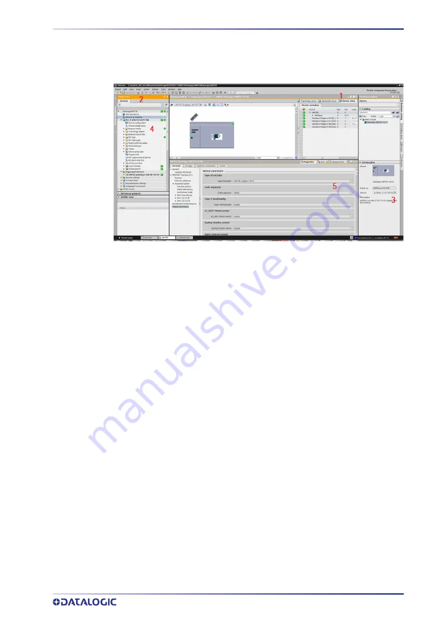
Figure 11. Online connection established
After the online connection has been established successfully, the user interface
changes (see the Figure above).
1. The title bar of the active window gets an orange background as soon as at least
one of the devices currently displayed in the editor has been successfully con
-
nected online. If one or more devices are unavailable, a symbol for a broken con
-
nection appears in the title bar of the editor.
2. Now the title bars of inactive windows for the relevant station have an orange line
below them.
3. An orange, pulsing bar appears at the right-hand edge of the status bar. If the con
-
nection has been established but it is not working properly, an icon for an inter
-
rupted connection is displayed instead of the bar. You will find more information
on the error in Diagnostics in the Inspector window.
4. Operating mode symbols or diagnostics symbols for the stations connected online
and their underlying objects are shown in the Project Tree. A comparison of the
online and offline status is also made automatically. Differences between online
and offline objects are also displayed in the form of symbols.
5. The Diagnostics > Device information area is brought to the foreground in the
Inspector window.
Closing an online connection
To close the existing online connection, follow these steps.
1. Select the device for which you want to disconnect the online connection in the
Project Tree.
2. Select the Go offline command in the Online menu bar. The online connection is
disconnected.
Содержание AMT58 Series
Страница 1: ......
Страница 8: ......
Страница 13: ...AMT58x CB CANopen 5 3 1 3 Fissaggio con flangia codice ST 58 FLNG ...
Страница 52: ......
Страница 55: ...Subject index ...
Страница 62: ...AMT58x PB Profibus 5 3 1 3 Installation using a flange code ST 58 FLNG ...
Страница 101: ......
Страница 102: ......
Страница 109: ......
Страница 114: ...AMT58x EC EtherCAT 5 3 1 3 Installation using a flange code ST 58 FLNG ...
Страница 166: ......
Страница 167: ...AMT58 PN INSTRUCTION MANUAL Absolute Encoders ...
Страница 179: ...INSTRUCTION MANUAL xiii SFC System function TCP Transmission Control Protocol TMAPC Master Application Cycle Time ...
Страница 180: ...LIST OF ABBREVIATIONS xiv AMT58 PN ...
Страница 213: ...RESETTING THE PARAMETERS TO THE DEFAULT FACTORY VALUES INSTRUCTION MANUAL 33 Figure 15 Encoder reset ...
Страница 221: ...TO TECHNOLOGY OBJECTS INSTRUCTION MANUAL 41 Figure 28 TO encoder enabled ...
Страница 231: ...INSTRUCTION MANUAL 51 ...
Страница 255: ...REAL TIME CLASS 3 IRT_TOP RT3 INSTRUCTION MANUAL 75 Figure 5 Telegram 81 IN Figure 6 Telegram 81 OUT ...
Страница 265: ...NORMAL OPERATION DIAGRAM INSTRUCTION MANUAL 85 NORMAL OPERATION DIAGRAM ...
Страница 266: ...ENCODER STATE MACHINE 86 AMT58 PN PRESET DIAGRAM ...
Страница 267: ...PARKING SENSOR DIAGRAM INSTRUCTION MANUAL 87 PARKING SENSOR DIAGRAM ...
Страница 268: ...ENCODER STATE MACHINE 88 AMT58 PN ERROR DIAGRAM Acknowledgment of acknowledgeable sensor error ...
Страница 269: ...ERROR DIAGRAM INSTRUCTION MANUAL 89 Acknowledgment of not acknowledgeable sensor error ...
Страница 284: ......
Страница 285: ......
Страница 287: ......
Страница 294: ......
Страница 299: ...AMT58x CB CANopen 5 3 1 3 Installation using a flange code ST 58 FLNG ...
Страница 335: ......
Страница 345: ...AMT58x DN DeviceNET 5 3 1 3 Installation using a flange code ST 58 FLNG ...
Страница 380: ...AMT58x DN DeviceNET 40 Default 21h ...
Страница 384: ...AMT58x DN DeviceNET 44 Default 00h ...
Страница 394: ......
Страница 404: ...AMT58x PB Profibus 5 3 1 3 Installation using a flange code ST 58 FLNG ...


